Advertisement
Quick Links
INTRODUCTION
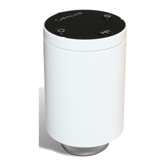
The ARV10RFM-3 is a battery-powered, mini-size thermostatic
radiator valve (TRV) controller using the ZigBee wireless
protocol. Simply replace the existing, passive head on the
standard 30mm radiator valve with the AVA10M30RF (referred
to from now on as the TRV). This allows you to convert
systems with one or two thermostat zones into individually
controlled zones. Pair up to 6 TRVs with the AWRT10RF
wireless thermostats. The SG888ZB Gateway creates the
Zigbee network. An optional AX10RF Receiver controller
may be used to control the boiler.
SYSTEM OVERVIEW
•
The Universal Gateway SG888ZB creates the Zigbee network.
•
The thermostat(s) and TRV(s) join the Zigbee network to control the radiator(s)
•
Up to 6 TRVs may be paired with a single thermostat.
•
If you are using an optional AX10RF Wireless Receiver to control the boiler:
o
If any thermostat calls for heat or, if the TRV is manually opened, the
AX10RF will energize the boiler
o
As each zone is satisfied, the associated TRV(s) will close.
o
The AX10RF will energize the boiler until all zones are satisfied, and then
turn-off.
See AX10RF and AWRT10RF manuals for more additional information.
CHECK COMPATIBILITY WITH THE RADIATOR VALVE
The SALUS TRV is compatible with most common thermostatic radiator valves.
Confirm dimensions
•
Thread diameter is 30mm (1.18in)
•
Valve pin length when open is between 13-16mm (0.51-0.62in)
If the dimensions do not match, it is recommended you change the radiator valve
If there are no threads near the valve pin (below), use the RA Adapter included with
the TRV
•
Slip the Adapter over the stem until it clicks in place
•
Make certain the adapter is fully seated
•
Tighten the collar screw
Joining the TRV
The TRV will remain in the Joining mode for 10 minutes after the first-time power has
been applied (out of the box) or it has been factory reset.
Prior to inserting the batteries in the TRV, prepare the AWRT and the App for joining.
1. From the App
1.1. Click Devices on the top menu bar
1.2. Click Add Devices in the drop-down menu
1.3. Click Scan Devices on the new page that opens
2. With the AWRT
2.1. Insert the Batteries, the AWRT will go through its boot process
2.2. When the display shows
display
PAIR? RDTR_VLV
2.3. Press SELECT button the display will show
counting down from
10:00
3. With the TRV
3.1. Remove TRV from the box
3.2. Remove side battery door
3.3. Insert batteries, ensuring
proper polarity
3.4. Replace cover
3.5. The LED will flash Orange, two
times, slowly
3.6. It will go through a sequence of
rapid
Red
and
Green
flashes
indicating the firmware versions (i.e. 14.4/6.3)
3.7. The LED will then flash
Green
Joining mode
3.8. Once the TRV Joins the network and Pairs with the AWRT, it will begin the
Adaptation process by retracting the valve stem pin
3.9. Press any button to initiate the Adaptation process
3.10. The TRV will remain in the Joining mode for 10 minutes
Wireless Radiator Valve
Model ARV10RFM-3
PAIR? RLY_CTRL
, press the ^ arrow once to
JOINING---
with a timer
(0.5s on/0.5s off) to indicate it is in the
4. From the App
4.1. Wait for devices to be found, click on the devices to:
4.2. Give the devices a meaningful name
4.3. From the dashboard, select the Thermostat you want to Pair the TRV with,
by clicking on the tile
4.4. Click on the Thermostat name
4.5. To edit, click the
on
4.6. Select the TRV - click box to turn Green, click Save
4.7. The TRV has now Joined the network and Paired with the Thermostat and
the LED will turn OFF
Note: If the TRV does not complete the Pairing process and no button is pressed
•
After 10 minutes the TRV will automatically retract the pin (LED rapidly
flashing Red) so the TRV may be mounted on the valve. During this
time, the TRV cannot Join/Pair
•
After 20 minutes, the TRV will initiate the Adaptation process. During
this time, the TRV cannot Join
•
Press the RADIO button for 10+ seconds to initiate the Joining mode
INSTALLATION
1.
Remove the existing head.
2.
Confirm the TRV pin is retracted (see 3.7
above)
3.
Thread the TRV onto the radiator valve.
NOTE: Rotate the TRV so that the
battery door is accessible
4.
Tighten the mounting ring finger-tight
to the valve
NOTE: Do not use tools or over tighten
5.
Press any button to initiate the Adaptation process which takes approximately
4 minutes as the TRV calibrates itself to the valve
5.1. The TRV will go through a sequence of
5.1.1. Closing the valve (LED flashes Green)
5.1.2. Opening the valve (LED flashes Orange)
5.1.3. Closing the valve (no LED however if you listen closely, you will hear
the valve motor running)
5.2. The TRV will position the valve based on the command from the AWRT
5.2.1. If the TRV has not Paired with the AWRT it will move to its Fail-Safe
position of 25% open
LED
Indicator
OPEN
NOTE: Once the TRV has completed the Adaptation process do not rotate the
TRV counterclockwise as it may loosen the mounting ring
ADDITIONAL FUNCTIONS
Auto Lock function
Once paired, the thermostat controls the TRV and after 5 minutes the TRV
buttons are locked.
•
To unlock – Press RADIO + CLOSE button for 3 seconds, LED flashes
Green
once
•
To lock – Press RADIO + CLOSE button for 3 seconds, LED flashes
once
•
TRV will Auto Lock after 5 minutes if no buttons are pressed.
CLOSE
RADIO
Red
Advertisement

Related Manuals for Salus ARV10RFM-3


Summary of Contents for Salus ARV10RFM-3
- Page 1 CHECK COMPATIBILITY WITH THE RADIATOR VALVE Confirm the TRV pin is retracted (see 3.7 above) The SALUS TRV is compatible with most common thermostatic radiator valves. Thread the TRV onto the radiator valve. Confirm dimensions NOTE: Rotate the TRV so that the •...
- Page 2 TRV receives no command from thermostat for 1+ hours Please visit www.salusinc.com for the most up to date documentation • Low battery • Temperature sensor malfunction SMC-QG- AVA10M30RF-EN-202111v1 When in the Fail-Safe mode the TRV can be manually opened or closed Copyright © SALUS North America, Inc. 2021...