
Related Manuals for ADTRAN Octal


Summary of Contents for ADTRAN Octal
- Page 1 Octal and Quad FXO Modules User Manual Part Number 1200310L1 (Octal) Part Number 1200329L1 (Quad) 61200310L1-1D July 2000...
- Page 2 901 Explorer Boulevard P.O. Box 140000 Huntsville, AL 35814-4000 (256) 963-8000 © 2000ADTRAN, Inc. All Rights Reserved. Printed in U.S.A.
- Page 3 If experiencing difficulty with this equipment, please contact ADTRAN at (256) 963-8722 for repair or warranty information. If the equipment is causing harm to the network, the telephone company may request this equipment to be disconnected from the network until the problem is resolved or it is certain that the equipment is not malfunctioning.
- Page 4 Federal Communications Commission (FCC) Radio Frequency Interference Statement This equipment has been tested and found to comply with the limits for a Class A digital device, pur- suant to Part 15 of the FCC Rules. These limits are designed to provide reasonable protection against harmful interference when the equipment is operated in a commercial environment.
- Page 5 Customer or a third party (including, but not limited to, loss of data or information, loss of profits, or loss of use). ADTRAN is not liable for damages for any cause whatsoever (whether based in contract, tort, or otherwise) in excess of the amount paid for the item.
-
Page 7: Table Of Contents
Features ............................... 1-1 Physical Description ..........................1-2 Chapter 2 Installation..........................2-1 Before Installing the Octal and Quad FXO Modules ................... 2-1 Shipping Contents ............................. 2-1 Installing the Octal and Quad FXO Modules ....................2-1 Wiring ................................. 2-2 Power Up and Initialization ..........................2-2 Failed Self-Test ............................ - Page 8 Port Name ..............................3-8 Rx Gain ............................... 3-8 Tx Gain ............................... 3-8 ATLAS 550 Features Used with Octal and Quad FXO Modules ............... 3-8 Factory Restore ............................3-8 Run Selftest ..............................3-8 Appendix A Dial Plan Interface Configuration ..................A-1 Index ................................Index-1...
-
Page 9: List Of Figures
Figure 2-1. Installing the Octal and Quad FXO Modules................2-1 Figure 3-1. Modules Menu..........................3-2 Figure 3-2. Menu Tree for Octal and Quad FXO Modules Menu ............3-3 Figure 3-3. Octal and Quad FXO Modules Menu Options ............... 3-5 Figure A-1. Dial Plan Menus ......................... A-1... - Page 10 List of Figures Octal and Quad FXO Modules User Manual 61200310L1-1...
-
Page 11: List Of Tables
List of Tables Table 2-1. Pinout Connection........................2-2 Table 3-1. Test 2W Information ........................3-7 61200310L1-1 Octal and Quad FXO Modules User Manual... - Page 12 List of Tables Octal and Quad FXO Modules User Manual 61200310L1-1...
-
Page 13: Chapter 1 Introduction
Chapter 1 OCTAL AND QUAD FXO MODULES OVERVIEW The Octal and Quad FXO Modules are for use in the ATLAS 550 family of products in applications that require analog phone interfaces. Potential applications include termination of analog PSTN trunks and connections to PBX station-side interfaces (OPX). -
Page 14: Physical Description
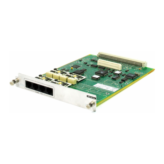
Chapter 1. Introduction Physical Description The Octal and Quad FXO Modules plug into any available option slot in the rear of the ATLAS 550 chassis. Figure 1-1 shows the Octal FXO Module. 500 Series Figure 1-1. Octal FXO Module The labels over the modular connectors refer to the corresponding ports on the Octal and Quad FXO Modules. -
Page 15: Chapter 2 Installation
Carefully unpack and inspect the modules for shipping damages. If you sus- pect damage occurred during shipping, file a claim immediately with the carrier and then contact ADTRAN Technical Support (see the last page of this manual for pertinent information). If possible, keep the original ship- ping container for returning the modules for repair or for verification of shipping damage. -
Page 16: Wiring
Tip to and from the analog phone interface POWER UP AND INITIALIZATION The Octal and Quad FXO Modules require no initialization input during the power-up sequence, as described in the ATLAS 550 User Manual. Any previ- ously configured setting for the Octal and Quad FXO Modules is automati- cally restored upon power-up. -
Page 17: Failed Self-Test
See the ATLAS 550 User Manual for details. Operation Alarms The red ALARM LED (located with the Module LEDs on the front panel) il- luminates when an alarm condition is detected. 61200310L1-1 Octal and Quad FXO Modules User Manual... - Page 18 Chapter 2. Installation Octal and Quad FXO Modules User Manual 61200310L1-1...
-
Page 19: Chapter 3 Operation
Quad FXO Module has four ports instead of eight and is displayed as FXO-4 in the menus. The Octal and Quad FXO Modules are controlled by the ATLAS 550 Base Unit terminal menu. The terminal menu allows for detailed configuration, status, and testing of the Octal and Quad FXO Modules. -
Page 20: Terminal Menu Structure
ODULES The ATLAS 550 system controller automatically detects the presence of the Octal and Quad FXO Modules when they are installed in the system. To see the menus for the Octal and Quad FXO Modules via the terminal menu, use... -
Page 21: Slt
Write security: 3; Read security: 5 Displays the type of module currently installed in the slot or the type of module you plan to install in the slot. If an Octal or Quad FXO Module is installed, the T field automatically defaults to FXO-8. -
Page 22: Menu
To access the submenus for this item, use the arrow keys to scroll to the column for the module you want to edit, and press . For detailed Enter information on each submenu item, see the section Octal and Quad FXO Mod- ules Menu Options on page 3-5. Read security: 5 LARM Displays an alarm condition on the module. -
Page 23: Rev
EVISION Displays the firmware revision. TATUS Displays the status of each of the eight Octal and Quad FXO Modules ports. Displays the port number. Displays the call status of each voice port. The port status field for each port TATUS may display the following: The port is preconfigured, but the FXO module is not present. -
Page 24: Tip Open
ESF RBS. Signaling bits have local significance only. For example, if the voice port is mapped to a DS0 that has been set up for E&M signaling, the voice port will still show LS/GS signaling. Octal and Quad FXO Modules User Manual 61200310L1-1... -
Page 25: Test
Activates Loopback tests per port as follows: OOPBACK Normal operation. Analog Loops the 2W test on itself. Digital Loops digital data entering the FXO on itself. Loopback tests disrupt calls in progress. 61200310L1-1 Octal and Quad FXO Modules User Manual... -
Page 26: Configuration
, a submenu of the ATLAS 550 main menu item T , executes ELFTEST ELFTEST both the Octal and Quad FXO Modules internal test and the ATLAS 550 in- ternal test. When R displays, place the cursor on it and press ELFTEST to execute the test. -
Page 27: Appendix A Dial Plan Interface Configuration
Dial Plan Interface Configuration Appendix A All references to the Octal FXO Module in this chapter are applicable to the Quad FXO Module, with the differences being that the Quad FXO Module has four ports instead of eight and is displayed as FXO-4 in the menus. - Page 28 Appendix A. Dial Plan Interface Configuration Octal and Quad FXO Modules: Network Termination To interface directly with the network (PSTN) or to interface to the station side of a PBX, configure the D as follows. Select N , and ETWORK define S as FXO+.
- Page 29 MSD set to 1, all digits would be sent toward the network TRIP except the leading 9. MSD does not affect C criteria. All of the digits TRIP CCEPT (including the MSDs that are subsequently stripped) are used as accept criteria. 61200310L1-1 Octal and Quad FXO Modules User Manual...
- Page 30 Slot 1 be switched to Port 2 of that same module. Assign a unique Source ID (e.g., 7) to Port 1 of the module, and then configure Port 2 to only accept calls from that unique Source ID (7). Octal and Quad FXO Modules User Manual 61200310L1-1...
-
Page 31: Index
3-5 red alarm 2-3 Idle, Status 3-5 restore factory defaults 3-8 Ifce Config A-1 Rev 3-5 Inactive, Status 3-5 Reverse Battery, Status 3-6 Info 3-5 ring output 3-7 initialization 2-2 61200310L1-1 Octal and Quad FXO Modules User Manual Index-1... - Page 32 Tx Gain 3-8 Offline/No Response 3-4 Type 3-3 Online 3-4 Reverse Battery 3-6 Test 3-6 warranty v Test – LC – No Battery 3-6 wiring 2-2 Test – LC – T/R Rolled 3-6 Index-2 Octal and Quad FXO Modules User Manual 61200310L1-1...
- Page 33 Applications Engineering (800) 615-1176 Sales (800) 827-0807 Post-Sale Support Please contact your local distributor first. If your local distributor cannot help, please contact ADTRAN Technical Support and have the unit serial number available. Technical Support (888) 4ADTRAN Repair and Return If ADTRAN Technical Support determines that a repair is needed, Technical Support will coordinate with the Customer and Product Service (CAPS) department to issue an RMA number.