
Related Manuals for Ericsson F251m


Summary of Contents for Ericsson F251m
- Page 1 1/70 User guide F251m terminal Fixed Cellular Terminal for Small office Home office (SoHo) applications...
-
Page 2: Table Of Contents
2/70 F251m ..................6 SUPPLIED PARTS ..............7 EXTERNAL CONNECTORS AND LIGHT INDICATORS... 7 SIM CARD ................8 CONNECTIONS ............... 8 Installing the FCT as a telephone line ........8 Installing an FCT connected to a PBX ........9 Preparing your FCT ..............11 5.3.1... - Page 3 3/70 11.4.2 Making a second call ............... 29 11.4.3 Receiving a second call ............29 11.4.4 Conference calls............... 30 11.4.5 Connecting active and held calls ..........30 11.5 Phonebook (abbreviated dialing)..........30 11.6 Voice mail................31 11.7 Sending tone signals ..............31 11.8 Controlling call time (minute minder)........
- Page 4 4/70 17.1 Limited Warranty Conditions ..........63 17.2 Ericsson Warranty ..............63 17.3 What Ericsson will do.............. 63 17.4 Conditions................64 REGULATORY INFORMATION ......... 66 DEFINITIONS ................ 68...
- Page 5 Improvements and changes to this manual needed by typographical errors, inaccuracies of current information, or improvements to programs and/or equipment, may be made by Ericsson Radio Systems, AB at any time and without notice. Such changes will, however, be incorporated into new editions of the manual.
-
Page 6: F251M
When there is no fixed infrastructure or if you need additional telephone lines: install the terminal run cabling from the F251m to any place within your Small office Home office (SoHo) and you will be ready to connect and use standard telephones,... -
Page 7: Supplied Parts
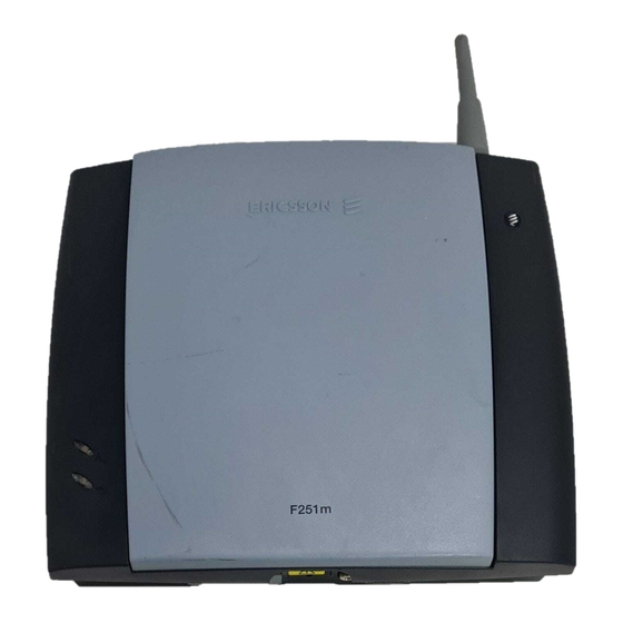
7/70 SUPPLIED PARTS After unpacking check that the following parts are included: - GSM FCT - Battery cable - AC power supply - Cable - Antenna - Wall bracket - 5m phone cable - Screws - User guide - DA20 (optional) – Alkaline (AA) holder (optional) EXTERNAL CONNECTORS AND LIGHT INDICATORS - GSM radio indicator (greed led) - Power indicator (red led) -
Page 8: Sim Card
8/70 - RS232 port - Maintenance connector - SIM card holder SIM CARD Your network operator provides you with a SIM (Subscriber Identity Module) card. The SIM card contains information about your telephone number and the services included in your subscription, among other things. -
Page 9: Installing An Fct Connected To A Pbx
9/70 Warning!: In order to avoid GSM interferences (noises), place the FCT at least 3 meters (horizontal) away from electronic devices, including the telephone equipment connected to the FCT, or other household electronic devices such as televisions or radio receivers. The difference in height should be at least 2 meters (vertical). - Page 10 • If the PBX does not offer LCR, choose the FCT trunk manually with a special dialed prefix. The F251m terminal is compatible with most analog PBXs on the market and with most of the available 2B+D ISDN digital output trunks, via its accessory ISDN FI12 adapter (see “FCT accessories”...
-
Page 11: Preparing Your Fct
11/70 Note: it is recommended that there is a minimum distance of 3 meters between the FCT and the PBX. The maximum cable distance between the PBX and the FCT should not exceed 600 meters, and the connection cable must be at least 0,4 mm2. Warning!: if you install more than one FCT to a PBX, their antennas have to be separated with a distance of 20 cm in height or 2 meters in horizontal. -
Page 12: Connect A Telephone To The Fct
12/70 3. Close the SIM card holder and place the front cover back in previous position. 5.3.2 Connect a telephone to the FCT Connect a fixed telephone to the FCT telephone line. Note: You will use this telephone for dialing the PIN number. 5.3.3 Switch on the FCT Connect the Power Supply. -
Page 13: Network Search
13/70 Most SIM cards are protected with a PIN (Personal Identity Number), which you get from your network operator and which you need in order to access the network. If the SIM card is not protected by the PIN code then you do not need to enter the PIN and the FCT starts automatically the Network Search. -
Page 14: Installing The Fct On The Wall
14/70 When a network is found, the Green Light Indicator switches on or flashes depending on the GSM signal strength. (See Light Indicators on page 6). Note: if the Green Light is off you do not have access to the GSM network at your present location. -
Page 15: Wall Mounting
15/70 Do not install the FCT in a bathroom, wet or damp basement or in an outdoor location. Do not install the FCT on walls or rooms that contain large amounts of metal, steel or wiring. Do not expose the FCT to extreme temperatures (near radiators, cooling vents, etc). - Page 16 16/70 3) Press the FCT down Warning!: once you have fixed the FCT to the wall and switch it on, check the final status of the Red and Green lights. If the Red and/or Green Lights are off, there is a problem with the power supply or the GSM signal.
-
Page 17: Connecting Fixed Line Devices
17/70 Note: if you want to remove the FCT from the wall bracket then you have to press the flap (step 1) as indicated in the following picture. And then push the FCT upwards (step 2). CONNECTING FIXED LINE DEVICES Connect the fixed line devices to the FCT (Telephone Line connector) with telephone wire in the same way as with an analog telephone line. -
Page 18: Checking Connections
18/70 Telephone Display PC modem Note: remember that you do not have to worry about the two wire Telephone cable polarity when making connections; if the two wires are reversed the FCT and the fixed line devices are not affected at all. Tip: if your house or company is already wired with telephone cable, you only need to connect the cable to the FCT RJ11 connector and your telephone line will be up and running in all... -
Page 19: Using Telephones
19/70 Use any of the telephones connected to the FCT and make a call. Check the speech quality and ask the receiver to call you back to confirm that you can also receive calls. If you have problems, see “Troubleshooting and FCT indicators”... - Page 20 20/70 Otherwise, you can alternatively dial each of the following sequences and check each time if the numbers appear on your CLI display by conducting the “Ring Back Test” after a specific sequence is dialed. You should find that one of the three sequences allows you to visualize the number “1234567890”...
-
Page 21: Using Fax Machines
21/70 USING FAX MACHINES The FCT terminal allows the connection of Group 3 analog faxes to the FCT telephone interface, in the same way as a telephone. Warning!: the fax communication service has to be registered with your network operator, as the network will not otherwise accept faxes to be sent/received. -
Page 22: Gprs Data Access Type
22/70 data calls (Internet browsing, e-mail, etc.) through the FCT line. To be able to send and receive data calls, you need: a PC equipped with an analog modem and the appropriate computer program (Web Browser, E-mail, etc). This is a standard configuration for most PCs in the market. -
Page 23: Gsm Data Access Type
23/70 Warning!: the GPRS data communication service has to be registered with your network operator, as the network will not otherwise accept GPRS calls. If your SIM card supports GPRS, your network operator must supply you with a user name and password in order to access the GPRS network, and optionally, to improve the Internet connection, a DNS address and a Proxy address. - Page 24 24/70 Tip: if you already have an Internet connection configured for the fixed line, you do not need to make any changes, just connect your PC to the FCT line instead of the fixed line. Warning!: if your modem is an old model and is not able to send the CNG tone, you should include *02* previous to the called number(B-number) in order to indicate the FCT that the call to be made is a data call (Example: *02*B-number).
-
Page 25: Using Pbx
25/70 USING PBX For a PBX connection, first, you should: • Check that the PBX fulfills the requirements for FCT connectivity (see “Installing an FCT connected to a PBX” on page 8) • Follow all FCT installation steps specified in “Preparing your FCT”... -
Page 26: Advanced Features
26/70 ADVANCED FEATURES If a DTMF telephone is connected to the FCT, the following features can be accessed 11.1 CHANGING VOLUME During a call, you can increase or decrease the received volume level. • Increase volume: dial R#### • Decrease volume: dial R**** 11.2 DIVERTING CALLS (CALL FORWARD) You can divert incoming calls to another phone number when... -
Page 27: Restricting Calls (Call Barring)
27/70 To manage With Dial … You will hear… diversion of calls … Function … Activate **21*Phone_number# 1 beep Always Deactivate ##21# 3 beeps 1 beep if activated Check status *#21# 3 beeps if deactivated Activate **67*Phone_number# 1 beep When busy Deactivate ##67# 3 beeps... -
Page 28: More Than One Call (Call Wait, Call Hold, Call Transfer, Multiparty Call)
28/70 Warning!: these dialing sequences may vary depending on your network operator. If these do not work, please consult your network operator or check the user guide provided with your subscription. To manage With Dial … You will hear… restriction of calls Function …... -
Page 29: Call Waiting Service
29/70 You can handle more than one call simultaneously. example, you can put an ongoing call on hold, while you make or answer a second call, and then switch between the two calls. You can also set up a Conference call to have a joint conversation with up to four people. -
Page 30: Conference Calls
30/70 • To continue the ongoing call and reject the waiting call: press R 0 • To put the ongoing call on hold and answer the waiting call: press R 1 • To end the ongoing call and answer the waiting call: press Note: if divert when busy is on, the waiting call is diverted to the number you have specified 11.4.4... -
Page 31: Voice Mail
31/70 Warning!: Pos has to have two digits always. For example, memory position number 1 has Pos=01 To manage the With Dial … You will hear… phonebook in … Function … Store **51*Pos*Phone_number# 1 beep SIM card memory Delete #51*Pos# 3 beeps 1 beep if memorized Check position... -
Page 32: Controlling Call Time (Minute Minder)
32/70 During a call, you can press keys 0-9, * and # to perform banking by phone or other interactive services, or control an answering machine. 11.8 CONTROLLING CALL TIME (MINUTE MINDER) If the minute minder is activated, you hear a beep once every minute during a call as a reminder of the duration of the ongoing call. -
Page 33: Two Voice Lines (Alternate Line Service)
33/70 Note: if instead of hearing beeps you hear a loud and low tone, this means that there has been an error in the activation or deactivation 11.10 TWO VOICE LINES (ALTERNATE LINE SERVICE) If your SIM card supports the Alternate line service, your FCT has two voice lines with different phone numbers, separate bills and perhaps different subscription services. -
Page 34: To Unblock Your Sim Card
34/70 Most SIM cards are locked at the time of purchase. If the SIM card lock is on, you have to enter your PIN (Personal Identity Number) the first time you use your FCT. see “Enter PIN” on page 11. Note: once you have entered the PIN code for the first time you will not have to enter it again unless you change your SIM card. -
Page 35: Troubleshooting And Fct Indicators
35/70 TROUBLESHOOTING AND FCT INDICATORS This chapter describes the procedures to identify and, if possible, correct problems that might occur with the FCT or its installation. Some problems require that you call your network operator, but most problems you encounter you can easily correct yourself. - Page 36 36/70 Note: if you have the DA20 display adapter accessory (See “FCT accessories” on page 41), a “Power failure” message will show on your display when the FCT is powered from the battery backup. When both red and green light indicators are flashing simultaneously, it means that the FCT is under Alarm conditions.
- Page 37 37/70 The following table summarizes the different operating status of your FCT depending on the light indicators, and what to do if a problem is encountered. If the problem persists, please contact your distributor or network operator. Light indicators status If you see…...
-
Page 38: Audible Tones
38/70 12.2 AUDIBLE TONES The FCT generates audible tones in your telephone set, thus providing the same service characteristics as the one given by the traditional fixed network. The following table describes the nature of the main tones you will get when using the unit. Other standard call progress tones, such as busy tone, number obtainable or ring back tone, are provided directly by the network. -
Page 39: Fct Technical Data
39/70 FCT TECHNICAL DATA GSM AIR INTERFACE Frequency Bands: Triple-Band E-GSM 900, GSM 1800 and GSM 1900 E-GSM 900 Frequencies: TX 880-915 MHz, RX 925-960 MHz RF power: Maximum 2 W (33 dBm), Power class 4 GSM1800 Frequencies: TX 1710-1785 MHz, RX 1805-1880 MHz RF power: Maximum 1 W (30 dBm), Power class 1 GSM1900... - Page 40 40/70 • Analog Data: V.90, V.34, V.32bis, V.32, V.22bis, V.22, V.23, V.21, Bell 212A & 103 • CLI: ETSI DTMF and V.23; Bellcore FSK • Line Impedance: 600 ohm (default) • Loop Current: 25 mA (off-hook) • Open loop voltage: 48 V (on-hook) •...
- Page 41 41/70 PRODUCT PRESENTATION Basic Kit: F251m Business, Power Supply, Mains cable, Wall mount bracket, Internal antenna, User guide FCT Size: Height 148 mm, Width 165 mm, Depth 45 mm FCT Weight: 300 grams...
-
Page 42: Fct Accessories
The FI12 Adapter has been specifically designed to provide a direct interface between the analog port of the FCT (F250m, F251m, F2412m and F271m) and a PBX with basic access (BA), 2B+D ISDN trunk lines. The FI12 Adapter behaves in the same way as an ISDN... -
Page 43: Display Adapter Da20
43/70 • CLIP (Call Line Identification Protocol) FI12 Size: Height 132mm, width 99mm, depth 34 mm FI12 Weight: 208 grams 14.2 DISPLAY ADAPTER DA20 The FCT display -DA20- is easy to install: simply plug it in into the telephone line in the most suitable place and you will benefit from the following features: •... - Page 44 Due to the standard nature of these batteries, they are not supplied by Ericsson. No NiMH or NiCd rechargeable batteries are allowed. Warning!: Ericsson recommends precaution when handling lead-acid batteries and also special attention over storage and power loss issues. See Safe and Efficient Use on page 57...
-
Page 45: Annex: Pc Data Configurations
45/70 ANNEX: PC DATA CONFIGURATIONS 15.1 WINDOWS 98 GPRS SET-UP Warning!: your PC must have the Dial-up Networking and TCP/IP protocol installed within network components. You can check this in ‘Start->Settings- >Control Panel’ and double clicking on ‘Network’. If not, these components have to be previously added from your Windows installation disk. - Page 46 46/70 4) Click on ‘Finish’. 5) In the ‘Dial-Up Networking’ folder, right-click on the created connection and select ‘Properties’.
- Page 47 47/70 6) In the ‘General’ tab, turn off ‘Use area code and Dialing Properties’.
- Page 48 48/70 7) In the ‘Server Types’ tab: – ‘Type of Dial-Up Server’: select ‘PPP: Internet, Windows NT, Windows 98’ from the list. – Check that ‘Advanced options’ and ‘Allowed network protocols’ are filled in as shown below: 8) Push the ‘TCP/IP Settings…’ button. –...
- Page 49 49/70 – ‘Use default gateway on remote network’ turned on. 9) Click ‘OK’ all the way to update the configuration. You have now installed the GPRS connection. To connect to the GPRS network, follow steps 1 to 3: 1) Go to ‘My Computer’-> Dial-Up Networking’ and open the previously configured connection.
-
Page 50: Windows Nt Gprs Set-Up
50/70 3) Once you are connected, you may use your connection as an ordinary Internet connection. Note: if your network operator has provided you with a Proxy Address, you should configure your Web browser (Internet Explorer, Netscape, etc.) accordingly. 15.2 WINDOWS NT GPRS SET-UP Warning!: your PC must have the Remote Access Service and the TCP/IP protocol installed within the network... - Page 51 51/70 >Control Panel’ and double clicking on ‘Network’. If not, these components have to be previously added from your Windows installation disk. To configure your GPRS connection under a Windows NT PC, follow steps 1 to 8: 1) Go to ‘My Computer’ and double-click ‘Dial-Up Networking’.
- Page 52 52/70 4) Within the ‘Basic’ tab, type a name for the connection in the ‘Entry name’ field. In the ‘Dial using’ field select the analog modem already installed on your PC. 5) In the ‘Server’ tab select ‘PPP: Windows NT, Windows 95 Plus, Internet’...
- Page 53 53/70 6) Push the ‘TCP/IP Settings…’ button. – ‘Server assigned IP address’ must be checked. – ‘Server assigned name server addresses’ must be set if network operator requires it. If the network operator provides DNS addresses, then these must be added once ‘Specify name server addresses’...
- Page 54 54/70 7) Press ‘OK’ and go to the ‘Security’ tab. Select ‘Accept any authentication including clear text’.
- Page 55 55/70 8) Click ‘OK’ all the way to update the configuration. You have now installed the GPRS connection. To connect to the GPRS network, follow steps 1 to 3: 1) Go to ‘My Computer -> Dial-Up Networking’ and select the Dial-Up Networking connection previously configured. Verify that the telephone number is *98#.
- Page 56 56/70 3) Once you are connected, you may use your connection as an ordinary Internet connection. Note: if your network operator has provided you with a Proxy Address, you should configure your Web browser (Internet Explorer, Netscape, etc.) accordingly.
-
Page 57: Safe And Efficient Use
Only Ericsson Service Points or Certified Service Centres should perform service. • Do not use any accessories other than Ericsson originals with the exception of products approved by Bluetooth Qualification Review Board. Use of non-Ericsson original accessories may result in loss of performance, damage to the product, fire, electric shock or injury. -
Page 58: Radio Frequency Energy
The system that handles your call when you are using your FCT controls the power level at which your FCT transmits. All Ericsson terminals are designed to not exceed the limits for exposure to RF energy set by national authorities and international health agencies. -
Page 59: Potentially Explosive Atmospheres
59/70 • Pacemaker patients should be aware that the use of an FCT very close to a pacemaker might cause the device to malfunction. • Some hearing aids might be disturbed if placed very near the FCT. Multiple electrical devices connected to the AC power outlet that is used by the FCT terminal may generate excessive interference to the FCT terminal. -
Page 60: Children
60/70 • Make sure the cord is positioned so that it will not be stepped on, tripped over or otherwise subjected to damage or stress. 16.7 CHILDREN DO NOT ALLOW CHILDREN TO PLAY WITH YOUR FCT SINCE IT CONTAINS SMALL PARTS THAT COULD BECOME DETACHED AND CREATE A CHOKING HAZARD. -
Page 61: Disposing Of The Battery
61/70 Warning!: when a battery is not installed or is connected to an FCT that is switched off, it should be recharged during 24 hours every 6 months. • Do not expose the battery to extreme temperatures, never above +60°C. For maximum battery capacity, use the battery in room temperature. -
Page 62: Accessing The Battery Compartment
62/70 Turn off the FCT by disconnecting the power supply as well as the battery (if it is installed). If you are transporting the FCT on an aircraft, you will be asked to remove the battery from the unit. For updated information about the transportation and use of wireless communication equipment, contact the appropriate local and national regulatory agency or your service provider. -
Page 63: Limited Warranty
• Read the Guidelines for safe and efficient use. • Read all of the terms and conditions of the Ericsson Warranty listed below. • Save your original receipt, which is necessary for warranty repair claims. -
Page 64: Conditions
4. This warranty does not cover product failures due to repair installations, modifications or improper service performed by a non-Ericsson authorized service workshop, opening of the Product by a non-Ericsson authorized person or use of non-Ericsson original accessories. 5. Batteries are not covered by this warranty. - Page 65 65/70 EXTENT THOSE DAMAGES CAN BE DISCLAIMED BY LAW. Some countries do not allow for the exclusion or limitation of loss of profits, commercial loss, incidental or consequential damages, or limitation of the duration of implied warranties, so the preceding limitations or exclusions may not be applicable in certain cases.
-
Page 66: Regulatory Information
66/70 REGULATORY INFORMATION Declaration of Conformity We, Ericsson Radio Systems AB of Kistagången 26, Kista S-16480 Stockholm, Sweden declare under our sole responsibility that our product Ericsson type 0130101-BV and in combination with our accessories, to which this declaration relates is in conformity with the appropriate standards 3GPP TS 51.010-1, EN 301 489-7 and EN 60950,... - Page 67 67/70 This device complies with Part 15 of the FCC rules. Operation is subject to the following two conditions: (1) This device may not cause harmful interference, and (2) This device must accept any interference received, including interference that may cause undesired operation.
-
Page 68: Definitions
68/70 DEFINITIONS The following definitions are supplied in order to better understand certain concepts included in this manual: Switch-on: power up the FCT by connecting the AC power supply or a charged battery. Switch-off: power down the FCT by disconnecting the AC power supply or removing the battery. - Page 69 69/70 and receive calls. It contains all the information from your subscription characteristics.
- Page 70 70/70 Visit us on our web site: http://www.ericsson.com/wireless/products/fixed Ericsson España, S.A. Bilbao Techonogy Centre Parque Tecnológico 700 E-48160 Derio Spain...