Advertisement
Quick Links
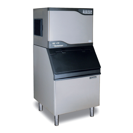
MV SERIES
MV SERIES
CUBERS
CUBERS
TECHNICAL SERVICE TRAINING
TECHNICAL SERVICE TRAINING
Welcome to another
Scotsman
technical
service
presentation
.
This
Welcome to another
Scotsman
technical
service
presentation
.
This
one will
cover
the
NEW MV
Series Modular Ice Cube Machines
one will
cover
the
NEW MV
Series Modular Ice Cube Machines
models
MV 300,
MV 450 , MV 600
and
MV 1000
.
models
MV 300,
MV 450 , MV 600
and
MV 1000
.
Advertisement

Related Manuals for Scotsman MV Series


Summary of Contents for Scotsman MV Series
- Page 1 MV SERIES MV SERIES CUBERS CUBERS TECHNICAL SERVICE TRAINING TECHNICAL SERVICE TRAINING Welcome to another Scotsman technical service presentation This Welcome to another Scotsman technical service presentation This one will cover NEW MV Series Modular Ice Cube Machines one will...
- Page 2 MV 300-450-600-1000 MV 300-450-600-1000 TOPICS TOPICS On the next slides are shown the following steps by steps procedures: • UNPACKING • UNPACKING • INSTALLATION • INSTALLATION • START UP AND OPERATIONAL CHECKS • START UP AND OPERATIONAL CHECKS • OPERATING PRINCIPLES and COMPONENTS •...
- Page 3 MV 300-450-600-1000 MV 300-450-600-1000 UNPACKING UNPACKING UNPACKING...
- Page 4 MV 300-450-600-1000 MV 300-450-600-1000 UNPACKING UNPACKING The machines are supplied in a carton box secured by two plastic strips to a wooden base. Check first the outside conditions of carton box and wooden base then cut the two plastic strips, remove the tape and then the carton box.
- Page 5 MV 300-450-600-1000 MV 300-450-600-1000 UNPACKING UNPACKING MV 450-600-1000 MV 450-600-1000...
- Page 6 MV 300-450-600-1000 MV 300-450-600-1000 UNPACKING UNPACKING Visually inspect the exterior of the machine then remove the front panel…. ……… ……..and the two side panels …..
- Page 7 MV 300-450-600-1000 MV 300-450-600-1000 UNPACKING UNPACKING Remove the water inlet and outlet hoses as well as……..
- Page 8 MV 300-450-600-1000 MV 300-450-600-1000 UNPACKING UNPACKING ……….the air baffle on the air cooled version.
- Page 9 MV 300-450-600-1000 MV 300-450-600-1000 UNPACKING UNPACKING Unscrew the unit frame from the wooden base….
- Page 10 MV 300-450-600-1000 MV 300-450-600-1000 UNPACKING UNPACKING The Modular Cuber machines require for the installation the use of a companion storage bin to store the ice produced. Storage bins required are: • B 193 for MV 300 • B 393 for MV 450-600-1000 B 193...
- Page 11 MV 300-450-600-1000 MV 300-450-600-1000 UNPACKING UNPACKING Unpack the storage bin and visually inspect the exterior then remove from the inside the carton box containing the legs as well as the drain hose and the plastic scoop.
- Page 12 MV 300-450-600-1000 MV 300-450-600-1000 INSTALLATION INSTALLATION INSTALLATION...
- Page 13 MV 300-450-600-1000 MV 300-450-600-1000 INSTALLATION INSTALLATION On B 193/393 Storage Bin install the four legs and their adjusting leveling nuts on the bottom base.
- Page 14 MV 300-450-600-1000 MV 300-450-600-1000 INSTALLATION INSTALLATION Place the storage bin in its definitive location then install on top of its upper side the rubber gasket then….
- Page 15 MV 300-450-600-1000 MV 300-450-600-1000 INSTALLATION INSTALLATION …...install on top of the same the ice machine and secure it with the two screws.
- Page 16 MV 300-450-600-1000 MV 300-450-600-1000 INSTALLATION INSTALLATION Remove the plastic tape securing the plastic cover to the vertical evaporator then….
- Page 17 MV 300-450-600-1000 MV 300-450-600-1000 INSTALLATION INSTALLATION …..remove one O ring and the plastic cover.
- Page 18 MV 300-450-600-1000 MV 300-450-600-1000 INSTALLATION INSTALLATION Take out the adhesive tape holding the Ice Thickness Sensor to the front cells of the evaporator then re-install the plastic cover with its O ring.
- Page 19 MV 300-450-600-1000 MV 300-450-600-1000 INSTALLATION INSTALLATION On air cooled version unloose the three screws securing the air cooled condenser to the unit frame….
- Page 20 MV 300-450-600-1000 MV 300-450-600-1000 INSTALLATION INSTALLATION …. and install the metal plate (air baffle) on the back side of the machine so….
- Page 21 MV 300-450-600-1000 MV 300-450-600-1000 INSTALLATION INSTALLATION …. to minimize the possible recycling of hot air through the right side lowered panel.
- Page 22 MV 300-450-600-1000 MV 300-450-600-1000 INSTALLATION INSTALLATION The installation of the metal plate (air separator) grants also a minimum distance TOP VIEW between the back side of MINIMUM MINIMUM the machine and the wall DISTANCE DISTANCE so to assure a correct and adequate ventilation.
- Page 23 MV 300-450-600-1000 MV 300-450-600-1000 INSTALLATION INSTALLATION Check the data plate of the machine located on the rear panel for correct voltage as well as for the proper wiring/fuse size. Remember that all machines require a solid earth wire.
- Page 24 MV 300-450-600-1000 MV 300-450-600-1000 INSTALLATION INSTALLATION Check for the correct water and ambient conditions that should be: • Min. ambient temperature 10ºC (50F) • Min. ambient temperature 10ºC (50F) • Max. ambient temperature 40ºC (100F) • Max. ambient temperature 40ºC (100F) •...
- Page 25 MV 300-450-600-1000 MV 300-450-600-1000 INSTALLATION INSTALLATION Adequate Min. space 15 cm space must left for proper water and electrical connections on the rear side of the machine and a minimum clearance of 15 cm on right side for best routing air.
- Page 26 MV 300 MV 300 INSTALLATION - AIR CIRCULATION INSTALLATION - AIR CIRCULATION FAN MOTOR CONDENSER COLD AIR COLD AIR HOT AIR HOT AIR COMPRESSOR ICE CHUTE EVAPORATOR OPENING...
- Page 27 MV 450-600-1000 MV 450-600-1000 INSTALLATION - AIR CIRCULATION INSTALLATION - AIR CIRCULATION FAN MOTOR CONDENSER COLD AIR COLD AIR COMPRESSOR HOT AIR HOT AIR ICE CHUTE EVAPORATOR OPENING...
- Page 28 MV 450-600-1000 MV 450-600-1000 STACKING INSTALLATION STACKING INSTALLATION Stacking installation require the use of a special ice chute connection to be installed on the bottom machine.
- Page 29 MV 300-450-600-1000 MV 300-450-600-1000 INSTALLATION INSTALLATION Level the unit on both directions front to rear and right to left side using the adjustable legs.
- Page 30 MV 300-450-600-1000 MV 300-450-600-1000 INSTALLATION - ELECTRICAL INSTALLATION - ELECTRICAL Install, on the cable supply with the machine, an adaguate electrical plug according to the local standards and regulations. Maximum voltage variation should be ±10%. Machine must be individually fuse protected.
- Page 31 MV 300-450-600-1000 MV 300-450-600-1000 INSTALLATION - WATER IN INSTALLATION - WATER IN Connect the water inlet 3/4” male threat of the water inlet fitting to the water supply line by means of the rubber hose provided with machine. Install on water supply line closed to the machine a...
- Page 32 MV 300-450-600-1000 MV 300-450-600-1000 INSTALLATION - WATER DRAIN INSTALLATION - WATER DRAIN Connect the 20 mm O.D. fitting of the water drain with the flexible hose supply with the machine with its proper clamp. As water will be mainly drained under pressure (by water pump) it is not necessary...
- Page 33 MV 300-450-600-1000 MV 300-450-600-1000 TYPICAL INSTALLATION TYPICAL INSTALLATION AIR COOLED AIR COOLED POWER HAND DISCONNECT SWITCH WATER INLET WATER VALVE WATER FILTER WATER DRAIN WATER DRAIN...
- Page 34 MV 300-450-600-1000 MV 300-450-600-1000 TYPICAL INSTALLATION TYPICAL INSTALLATION WATER COOLED WATER COOLED POWER HAND DISCONNECT SWITCH WATER INLET WATER VALVE WATER FILTER WATER DRAIN WATER DRAIN...
- Page 35 MV 300-450-600-1000 MV 300-450-600-1000 START UP AND START UP AND START UP AND OPERATIONAL OPERATIONAL OPERATIONAL CHECKS CHECKS CHECKS...
- Page 36 MV 300-450-600-1000 MV 300-450-600-1000 START UP AND OPERATIONAL CHECKS START UP AND OPERATIONAL CHECKS • Open the water tap/valve.
- Page 37 MV 300-450-600-1000 MV 300-450-600-1000 START UP AND OPERATIONAL CHECKS START UP AND OPERATIONAL CHECKS • Switch ON the power on the electrical supply line.
- Page 38 MV 300-450-600-1000 MV 300-450-600-1000 START UP START UP The machine enter in the Start Up mode with the PC Board energized as well as the Green LED of the machine under power. Green LED machine in operation is energized too, blinking fast for 40 seconds.
- Page 39 MV 300-450-600-1000 MV 300-450-600-1000 START UP START UP During the Start Up cycle the components in operation are: • Hot gas valve...
- Page 40 MV 300-450-600-1000 MV 300-450-600-1000 START UP START UP During the Start Up cycle the components in operation are: • Hot gas valve • Water Drain Valve...
- Page 41 MV 300-450-600-1000 MV 300-450-600-1000 START UP START UP During the Start Up cycle the components in operation are: • Hot gas valve • Water Drain Valve • Water Pump...
- Page 42 MV 300-450-600-1000 MV 300-450-600-1000 FREEZING CYCLE FREEZING CYCLE Start up cycle resuming chart Start up cycle resuming chart Start up cycle resuming chart Compressor Compressor Water inlet valve Water inlet valve Water pump Water pump Hot gas valve Hot gas valve Water drain valve Water drain valve 40''...
- Page 43 MV 300-450-600-1000 MV 300-450-600-1000 FREEZING CYCLE FREEZING CYCLE After the Start Up cycle the machine enters directly into the Freezing cycle with the following components energized: • Water Inlet Valve...
- Page 44 MV 300-450-600-1000 MV 300-450-600-1000 FREEZING CYCLE FREEZING CYCLE • Water Inlet Valve • Compressor...
- Page 45 MV 300-450-600-1000 MV 300-450-600-1000 FREEZING CYCLE FREEZING CYCLE • Water Inlet Valve • Compressor • Fan motor (in continuous operation for the first 3 minutes)
- Page 46 MV 300-450-600-1000 MV 300-450-600-1000 FREEZING CYCLE FREEZING CYCLE The LED energized are: • Machine under power • Machine in operation (steady) ALARM POWER OPER. FULL ALARM RE-SET PRESS.
- Page 47 MV 300-450-600-1000 MV 300-450-600-1000 FREEZING CYCLE FREEZING CYCLE Water is coming into the water reservoir of the machine through the Water Inlet Solenoid Valve..
- Page 48 MV 300-450-600-1000 MV 300-450-600-1000 FREEZING CYCLE FREEZING CYCLE ….till the water reservoir if filled up to the maximum level….
- Page 49 MV 300-450-600-1000 MV 300-450-600-1000 FREEZING CYCLE FREEZING CYCLE ….controlled by a Water Level Sensor.
- Page 50 MV 300-450-600-1000 MV 300-450-600-1000 FREEZING CYCLE FREEZING CYCLE 30 seconds later, the Water Pump starts up.
- Page 51 MV 300-450-600-1000 MV 300-450-600-1000 FREEZING CYCLE FREEZING CYCLE After 3 minutes from the start up of the freezing cycle, the Water Inlet Solenoid Valve is activated again for few seconds till the water reaches the maximum level so to reduce any possible slush ice formation...
- Page 52 MV 300-450-600-1000 MV 300-450-600-1000 FREEZING CYCLE FREEZING CYCLE In the meantime the condenser sensor starts to transmit the current to the PC Board…..
- Page 53 MV 300-450-600-1000 MV 300-450-600-1000 FREEZING CYCLE FREEZING CYCLE …. keeping in operation the Fan Motor in ON-OFF mode according to the condenser temperature.
- Page 54 MV 300-450-600-1000 MV 300-450-600-1000 FREEZING CYCLE FREEZING CYCLE The machine remains in the freezing cycle with the ice that become thicker ….
- Page 55 MV 300-450-600-1000 MV 300-450-600-1000 FREEZING CYCLE FREEZING CYCLE ……till the two metal plates of the Ice Thickness Sensor are covered by the water cascading down through the front surface of the ice plate.
- Page 56 MV 300-450-600-1000 MV 300-450-600-1000 FREEZING CYCLE FREEZING CYCLE When the Power is transmitted back continuously to the PC Board through the metal plates of the Ice Thickness Sensor for more then 6 seconds, the….
- Page 57 MV 300-450-600-1000 MV 300-450-600-1000 FREEZING CYCLE FREEZING CYCLE ….machine enters in the Pre-Harvest first or directly into the Harvest Cycle mode according to: RISE UP THE CUT IN TEMPERATURE OF THE CONDENSER SENSOR TO 38°C AND GO STRAIGHT TO THE HARVEST EXTEND THE LENGTH OF CYCLE FREEZING CYCLE BY 30"...
- Page 58 MV 300-450-600-1000 MV 300-450-600-1000 FREEZING CYCLE FREEZING CYCLE Freezing cycle resuming chart Freezing cycle resuming chart Freezing cycle resuming chart Compressor Compressor Water inlet valve Water inlet valve Water pump 30" Water pump 30" Fan motor < 30°C 30" Fan motor < 30°C 30"...
- Page 59 MV 300-450-600-1000 MV 300-450-600-1000 WATER SYSTEM - FREEZE WATER SYSTEM - FREEZE...
- Page 60 MV 300-450-600-1000 MV 300-450-600-1000 HARVEST CYCLE HARVEST CYCLE During the harvest cycle the components in operation are: • Hot Gas valve...
- Page 61 MV 300-450-600-1000 MV 300-450-600-1000 HARVEST CYCLE HARVEST CYCLE • Hot Gas valve • Water Drain/Purge Valve...
- Page 62 MV 300-450-600-1000 MV 300-450-600-1000 HARVEST CYCLE HARVEST CYCLE • Hot Gas valve • Water Drain/Purge Valve • Water Pump for the first 40”...
- Page 63 MV 300-450-600-1000 MV 300-450-600-1000 HARVEST CYCLE HARVEST CYCLE • Hot Gas valve • Water Drain/Purge Valve • Water Pump for the first 40” • Compressor...
- Page 64 MV 300-450-600-1000 MV 300-450-600-1000 HARVEST CYCLE HARVEST CYCLE • Hot Gas valve • Water Drain/Purge Valve • Water Pump for the first 40” • Compressor ALARM and both LEDs POWER OPER. FULL ALARM RE-SET PRESS. • Machine Under Power • Machine in Operation...
- Page 65 MV 300-450-600-1000 MV 300-450-600-1000 HARVEST CYCLE HARVEST CYCLE 30 seconds after the beginning of the Harvest Cycle, the Water Inlet Solenoid Valve is energized for 10 seconds only in order to have a short flush of fresh water into the sump while the Water Pump is still in operation.
- Page 66 MV 300-450-600-1000 MV 300-450-600-1000 HARVEST CYCLE HARVEST CYCLE The Fan Motor remains in OFF mode unless the Condenser Sensor probe rise up to more then 38°C (same set up as per end of freezing cycle).
- Page 67 MV 300-450-600-1000 MV 300-450-600-1000 START UP AND OPERATIONAL CHECKS START UP AND OPERATIONAL CHECKS While the ice plate is falling down, it moves the front plastic cover out from the evaporator causing the activation of the magnetic switch to restart a new freezing cycle.
- Page 68 MV 300-450-600-1000 MV 300-450-600-1000 HARVEST CYCLE HARVEST CYCLE Harvest cycle resuming chart Harvest cycle resuming chart Compressor Water inlet valve 30" 10" Water pump 40" Hot gas valve Water drain valve...
- Page 69 MV 300-450-600-1000 MV 300-450-600-1000 WATER SYSTEM - HARVEST WATER SYSTEM - HARVEST 1ST PART - 30” 1ST PART - 30”...
- Page 70 MV 300-450-600-1000 MV 300-450-600-1000 WATER SYSTEM - HARVEST WATER SYSTEM - HARVEST 2ND PART - 10” 2ND PART - 10”...
- Page 71 MV 300-450-600-1000 MV 300-450-600-1000 WATER SYSTEM - HARVEST WATER SYSTEM - HARVEST 3RD PART 3RD PART...
- Page 72 MV 300-450-600-1000 MV 300-450-600-1000 OPERATING PRINCIPLES - BIN FULL OPERATING PRINCIPLES - BIN FULL When the last ice plate discharged from the evaporator doesn’t find any more space into the storage bin it remains in between the storage bin and the machine keeping…...
- Page 73 MV 300-450-600-1000 MV 300-450-600-1000 OPERATING PRINCIPLES - BIN FULL OPERATING PRINCIPLES - BIN FULL …….the plastic deflector/cover in open position.
- Page 74 MV 300-450-600-1000 MV 300-450-600-1000 OPERATING PRINCIPLES - BIN FULL OPERATING PRINCIPLES - BIN FULL By doing so the magnet portion of the magnetic switch is kept far from its sensor fore more then few seconds that it is equivalent to transmit the signal to the PC Board…...
- Page 75 MV 300-450-600-1000 MV 300-450-600-1000 BIN FULL BIN FULL In case the magnetic sensor remains open, during freezing or harvest cycle, for more then 30 seconds, the machine stops its operation in Bin Full with the glowing of the BIN FULL YELLOW LED.
- Page 76 MV 300-450-600-1000 MV 300-450-600-1000 ALARM CONDITIONS ALARM CONDITIONS Both the last two are ON steady: ALARM POWER OPER. FULL ALARM RE-SET PRESS.
- Page 77 MV 300-450-600-1000 MV 300-450-600-1000 ALARM CONDITIONS ALARM CONDITIONS Both the last two Red LED are ON STEADY: Condenser Sensor Condenser Sensor OUT OF ORDER OUT OF ORDER...
- Page 78 MV 300-450-600-1000 MV 300-450-600-1000 ALARM CONDITIONS ALARM CONDITIONS Both the last two are BLINKING SLOW: WATER ERROR WATER ERROR ALARM POWER OPER. FULL ALARM RE-SET PRESS.
- Page 79 MV 300-450-600-1000 MV 300-450-600-1000 ALARM CONDITIONS ALARM CONDITIONS Both the last two are BLINKING SLOW: WATER ERROR WATER ERROR Water level inside the water sump too low after 3 minutes from the activation of the Water Inlet Valve.
- Page 80 MV 300-450-600-1000 MV 300-450-600-1000 ALARM CONDITIONS ALARM CONDITIONS Both the last two are BLINKING FAST: ALARM POWER OPER. FULL ALARM RE-SET PRESS.
- Page 81 MV 300-450-600-1000 MV 300-450-600-1000 ALARM CONDITIONS ALARM CONDITIONS Both the last two ALARM are BLINKING POWER OPER. FULL ALARM RE-SET PRESS. FAST: RESET MODE RESET MODE Charging water through the Water Inlet Solenoid Valve after the tripping OFF on WATER ERROR...
- Page 82 MV 300-450-600-1000 MV 300-450-600-1000 ALARM CONDITIONS ALARM CONDITIONS The fourth Red LED BLINKING SLOW: ALARM POWER OPER. FULL ALARM RE-SET PRESS.
- Page 83 MV 300-450-600-1000 MV 300-450-600-1000 ALARM CONDITIONS ALARM CONDITIONS The fourth Red LED BLINKING SLOW: TOO HI TOO HI CONDENSING CONDENSING TEMPERATURE TEMPERATURE The condenser sensor detected a temperature > 65°C > 65°C...
- Page 84 MV 300-450-600-1000 MV 300-450-600-1000 ALARM CONDITIONS ALARM CONDITIONS The fourth Red LED ALARM BLINKING FAST: POWER OPER. FULL ALARM RE-SET PRESS. RESET MODE RESET MODE Condenser Sensor < 50°C Fan motor in operation for 3 minutes then back on Start Up Cycle Mode.
- Page 85 MV 300-450-600-1000 MV 300-450-600-1000 ALARM CONDITIONS ALARM CONDITIONS The fourth Red LED ON STEADY: ALARM POWER OPER. FULL ALARM RE-SET PRESS.
- Page 86 MV 300-450-600-1000 MV 300-450-600-1000 ALARM CONDITIONS ALARM CONDITIONS The fourth Red LED Harvest Cycle longer then 3’ 30” Harvest Cycle longer then 3’ 30” Harvest Cycle longer then 3’ 30” ON STEADY: ALARM POWER OPER. FULL ALARM RE-SET PRESS.
- Page 87 MV 300-450-600-1000 MV 300-450-600-1000 ALARM CONDITIONS ALARM CONDITIONS The fifth Red LED ON STEADY: ALARM POWER OPER. FULL ALARM RE-SET PRESS.
- Page 88 MV 300-450-600-1000 MV 300-450-600-1000 ALARM CONDITIONS ALARM CONDITIONS TOO HI DISCHARGE TOO HI DISCHARGE TOO HI DISCHARGE The fifth Red LED ON STEADY: PRESSURE > 33 bar 460 PSI PRESSURE > 33 bar 460 PSI PRESSURE > 33 bar 460 PSI ALARM POWER OPER.
- Page 89 MV 300-450-600-1000 MV 300-450-600-1000 ALARM CONDITIONS ALARM CONDITIONS The fifth Red LED BLINKING FAST: ALARM POWER OPER. FULL ALARM RE-SET PRESS. RESET MODE RESET MODE Push the Reset Button of the Pressure Control…..
- Page 90 MV 300-450-600-1000 MV 300-450-600-1000 ALARM CONDITIONS ALARM CONDITIONS The fifth Red LED BLINKING FAST: ALARM POWER OPER. FULL ALARM RE-SET PRESS. RESET MODE RESET MODE First the fan motor starts up for 3 minutes then…... the entire machine through the Start Up Cycle Mode.
- Page 91 MV 300-450-600-1000 MV 300-450-600-1000 ALARM CONDITIONS ALARM CONDITIONS The PC Board is also checking the maximum time of the freezing cycle that changes according to the operation of the fan motor during the freezing cycle (room temperature): • Fan motor in ON-OFF mode: Max.
- Page 92 MV 300-450-600-1000 MV 300-450-600-1000 ALARM CONDITIONS ALARM CONDITIONS Whenever the machine remains in the Freezing Cycle for the Maximum time (30 or 40 minutes), the PC Board moves the unit directly into the Harvest Cycle.
- Page 93 MV 300-450-600-1000 MV 300-450-600-1000 ALARM CONDITIONS ALARM CONDITIONS In case the Harvest Cycle takes longer In case the Harvest Cycle takes longer then 3’ 30”, the machine trips OFF with then 3’ 30”, the machine trips OFF with the glowing of the fourth Red LED. the glowing of the fourth LED.
- Page 94 MV 300-450-600-1000 MV 300-450-600-1000 ALARM CONDITIONS ALARM CONDITIONS The PC Board can be set up for: • Manual Reset • Manual Reset Mode (Jump IN) Mode (Jump IN)
- Page 95 MV 300-450-600-1000 MV 300-450-600-1000 ALARM CONDITIONS ALARM CONDITIONS The PC Board can be set up for: • Automatic Reset • Automatic Reset Mode (Jump OUT) Mode (Jump OUT)
- Page 96 MV 300-450-600-1000 MV 300-450-600-1000 ALARM CONDITIONS ALARM CONDITIONS Manual Reset Mode Manual Reset Mode To Restart the machine it is necessary to Push the RE-SET RE-SET BUTTON BUTTON...
- Page 97 MV 300-450-600-1000 MV 300-450-600-1000 ALARM CONDITIONS ALARM CONDITIONS Automatic Reset Mode Automatic Reset Mode The Automatic Reset Mode is activated only for the following ALARM CONDITIONS: ALARM CONDITIONS • WATER ERROR • WATER ERROR • TOO HIGH CONDENSING TEMPERATURE • TOO HIGH CONDENSING TEMPERATURE •...
- Page 98 MV 300-450-600-1000 MV 300-450-600-1000 Automatic Reset Mode Automatic Reset Mode In case the Water Level Sensor does NOT detect any presence of water, after the first 3 minutes of operation in the freezing cycle, the P C Board switches OFF the entire machine with the SLOW BLINKING of the last two RED ALARM...
- Page 99 MV 300-450-600-1000 MV 300-450-600-1000 ALARM CONDITIONS ALARM CONDITIONS Automatic Reset Mode Automatic Reset Mode WATER ERROR: WATER ERROR: The machine remains in OFF mode for 30’ then it tries to re-fill water: Water re-filled? YES: Machine remains in operation YES: Machine remains in operation Machine again in OFF mode for additional 30’...
- Page 100 MV 300-450-600-1000 MV 300-450-600-1000 Automatic Reset Mode Automatic Reset Mode Whenever the condenser sensor probe reaches the temperature of 65°C, the machine switches OFF in Alarm by the slow blinking of the 4th LED (TOO HIGH CONDENSING TEMPERATURE) ALARM POWER OPER.
- Page 101 MV 300-450-600-1000 MV 300-450-600-1000 ALARM CONDITIONS ALARM CONDITIONS Automatic Reset Mode Automatic Reset Mode TOO HI CONDENSING TEMPERATURE: TOO HI CONDENSING TEMPERATURE: As soon as the temperature of the Condenser Sensor is <50°C, the PC Board starts up first the fan motor for 3’ then the entire machine through the Start-Up Cycle.
- Page 102 MV 300-450-600-1000 MV 300-450-600-1000 ALARM CONDITIONS ALARM CONDITIONS Automatic Reset Mode Automatic Reset Mode TOO LONG HARVEST CYCLE: TOO LONG HARVEST CYCLE: After the 3’ 30” of the Harvest Cycle, the PC Board move back the machine into a new Freezing Cycle.
- Page 103 MV 300-450-600-1000 MV 300-450-600-1000 START UP AND OPERATIONAL CHECKS START UP AND OPERATIONAL CHECKS During the first 20 minutes of the freezing cycle, the PC Board stores information about the operation of the fan motor.
- Page 104 MV 300-450-600-1000 MV 300-450-600-1000 START UP AND OPERATIONAL CHECKS START UP AND OPERATIONAL CHECKS Accordingly to its operation, the maximum safety of the freezing cycle is equal to: • 30 minutes when Fan Motor works in ON-OFF mode • 40 minutes when Fan Motor is always ON...
- Page 105 MV 300-450-600-1000 MV 300-450-600-1000 START UP AND OPERATIONAL CHECKS START UP AND OPERATIONAL CHECKS The components energized at The components energized at beginning of the freezing cycle beginning of the freezing cycle are: are: • PC Board • PC Board...
- Page 106 MV 300-450-600-1000 MV 300-450-600-1000 START UP AND OPERATIONAL CHECKS START UP AND OPERATIONAL CHECKS The components energized at beginning of the freezing cycle are: • PC Board • Contactor...
- Page 107 MV 300-450-600-1000 MV 300-450-600-1000 START UP AND OPERATIONAL CHECKS START UP AND OPERATIONAL CHECKS The components energized at beginning of the freezing cycle are: • PC Board • Contactor • Compressor...
- Page 108 MV 300-450-600-1000 MV 300-450-600-1000 START UP AND OPERATIONAL CHECKS START UP AND OPERATIONAL CHECKS Few seconds later, as soon as the discharge pressure reaches 17 bar (240 PSI), the fan motor starts to operate in ON-OFF mode keeping the discharge pressure between 15 and 17 bar (210÷240 PSI).
- Page 109 MV 300-450-600-1000 MV 300-450-600-1000 START UP AND OPERATIONAL CHECKS START UP AND OPERATIONAL CHECKS The operation of the fan motor is controlled by a condenser temperature sensor located on the outlet of condenser that transmit a signal to the PC Board to activate in ON-OFF mode the fan motor.
- Page 110 MV 300-450-600-1000 MV 300-450-600-1000 START UP AND OPERATIONAL CHECKS START UP AND OPERATIONAL CHECKS The Water Pump The Water Pump starts up 1 minute starts up 1 minute later later so to allow the so to allow the evaporator to freeze evaporator to freeze up its outside surface up its outside surface...
- Page 111 MV 300-450-600-1000 MV 300-450-600-1000 START UP AND OPERATIONAL CHECKS START UP AND OPERATIONAL CHECKS While the water is falling dawn from the upper side of the evaporator it enter into the refrigerated cells starting the formation of a small layer of ice.
- Page 112 MV 300-450-600-1000 MV 300-450-600-1000 START UP AND OPERATIONAL CHECKS START UP AND OPERATIONAL CHECKS The machine remains in the freezing cycle with the ice that become thicker ….
- Page 113 MV 300-450-600-1000 MV 300-450-600-1000 START UP AND OPERATIONAL CHECKS START UP AND OPERATIONAL CHECKS ……till the two metal plates of the Ice Thickness Sensor are covered by the water falling dawn through the front surface of the ice plate.
- Page 114 MV 300-450-600-1000 MV 300-450-600-1000 START UP AND OPERATIONAL CHECKS START UP AND OPERATIONAL CHECKS By doing so a low voltage current is supply back to the PC Board using water as a conductor.
- Page 115 START UP AND OPERATIONAL CHECKS START UP AND OPERATIONAL CHECKS 10 seconds later the PC Board put the machine in the harvest cycle energizing the: • Hot Gas Valve...
- Page 116 MV 300-450-600-1000 MV 300-450-600-1000 START UP AND OPERATIONAL CHECKS START UP AND OPERATIONAL CHECKS 10 seconds later the PC Board put the machine in the harvest cycle energizing the: • Hot Gas Valve • Water drain Valve...
- Page 117 MV 300-450-600-1000 MV 300-450-600-1000 START UP AND OPERATIONAL CHECKS START UP AND OPERATIONAL CHECKS The other electrical components that remain energized during the harvest cycle are: • Compressor...
- Page 118 MV 300-450-600-1000 MV 300-450-600-1000 START UP AND OPERATIONAL CHECKS START UP AND OPERATIONAL CHECKS ……….and for the first 40’’ only • Water Pump...
- Page 119 MV 300-450-600-1000 MV 300-450-600-1000 START UP AND OPERATIONAL CHECKS START UP AND OPERATIONAL CHECKS The refrigerant in hot gas state, pumped by compressor, reaches the back side of the evaporator warming up its surface and partially melting the ice.
- Page 120 MV 300-450-600-1000 MV 300-450-600-1000 START UP AND OPERATIONAL CHECKS START UP AND OPERATIONAL CHECKS After one-one and half minute from the beginning of the harvest cycle, the ice plate is moving out from the evaporator cells….
- Page 121 START UP AND OPERATIONAL CHECKS START UP AND OPERATIONAL CHECKS ….falling down into the bottom storage bin.
- Page 122 MV 300-450-600-1000 MV 300-450-600-1000 START UP AND OPERATIONAL CHECKS START UP AND OPERATIONAL CHECKS In the meantime also the water drain valve and the water pump are energized pumping out the water from the sump so to reduce as much as possible the accumulation of scale into the...
- Page 123 MV 300-450-600-1000 MV 300-450-600-1000 OPERATING OPERATING OPERATING PRINCIPLES PRINCIPLES PRINCIPLES COMPONENTS COMPONENTS COMPONENTS...
- Page 124 MV 300-450-600-1000 MV 300-450-600-1000 OPERATING PRINCIPLES - FREEZE OPERATING PRINCIPLES - FREEZE Evaporator Evaporator Air cooled Air cooled valve valve condenser condenser Compressor Compressor...
- Page 125 MV 300-450-600-1000 MV 300-450-600-1000 OPERATING PRINCIPLES - HARVEST OPERATING PRINCIPLES - HARVEST Evaporator Evaporator Air cooled Air cooled valve valve condenser condenser Compressor Compressor...
- Page 126 MV 300-450-600-1000 MV 300-450-600-1000 WATER SYSTEM - FREEZE WATER SYSTEM - FREEZE...
- Page 127 MV 300-450-600-1000 MV 300-450-600-1000 WATER SYSTEM - HARVEST WATER SYSTEM - HARVEST 1ST PART - FIRST 30” - WATER PURGE OUT 1ST PART - FIRST 30” - WATER PURGE OUT...
- Page 128 MV 300-450-600-1000 MV 300-450-600-1000 WATER SYSTEM - HARVEST WATER SYSTEM - HARVEST 2ND PART - ADDITIONAL 10” - WASHING & PURGE OUT 2ND PART - ADDITIONAL 10” - WASHING & PURGE OUT...
- Page 129 MV 300-450-600-1000 MV 300-450-600-1000 WATER SYSTEM - HARVEST WATER SYSTEM - HARVEST 3RD PART - UP TO THE END OF HARVEST 3RD PART - UP TO THE END OF HARVEST...
- Page 130 MV 300-450-600-1000 MV 300-450-600-1000 COMPONENTS - REFRIGERANT SYSTEM COMPONENTS - REFRIGERANT SYSTEM The components of the refrigerant system of the MV series Models are composed by:...
- Page 131 MV 300-450-600-1000 MV 300-450-600-1000 COMPONENTS - REFRIGERANT SYSTEM COMPONENTS - REFRIGERANT SYSTEM LOCATION OF REFRIGERANT COMPONENTS LOCATION OF REFRIGERANT COMPONENTS • COMPRESSOR COMPRESSOR...
- Page 132 MV 300-450-600-1000 MV 300-450-600-1000 COMPONENTS - REFRIGERANT SYSTEM COMPONENTS - REFRIGERANT SYSTEM LOCATION OF REFRIGERANT COMPONENTS LOCATION OF REFRIGERANT COMPONENTS • COMPRESSOR • COMPRESSOR • CONDENSER CONDENSER...
- Page 133 MV 300-450-600-1000 MV 300-450-600-1000 COMPONENTS - REFRIGERANT SYSTEM COMPONENTS - REFRIGERANT SYSTEM LOCATION OF REFRIGERANT COMPONENTS LOCATION OF REFRIGERANT COMPONENTS • COMPRESSOR • COMPRESSOR • CONDENSER • CONDENSER • EVAPORATOR EVAPORATOR...
- Page 134 MV 300-450-600-1000 MV 300-450-600-1000 COMPONENTS - REFRIGERANT SYSTEM COMPONENTS - REFRIGERANT SYSTEM LOCATION OF REFRIGERANT COMPONENTS LOCATION OF REFRIGERANT COMPONENTS • COMPRESSOR • COMPRESSOR • CONDENSER • CONDENSER • EVAPORATOR • EVAPORATOR • TXV VALVE TXV VALVE...
- Page 135 MV 300-450-600-1000 MV 300-450-600-1000 COMPONENTS - REFRIGERANT SYSTEM COMPONENTS - REFRIGERANT SYSTEM LOCATION OF REFRIGERANT COMPONENTS LOCATION OF REFRIGERANT COMPONENTS • COMPRESSOR • COMPRESSOR • CONDENSER • CONDENSER • EVAPORATOR • EVAPORATOR • TXV VALVE • TXV VALVE • HEAT EXCHANGER HEAT EXCHANGER...
- Page 136 MV 300-450-600-1000 MV 300-450-600-1000 COMPONENTS - REFRIGERANT SYSTEM COMPONENTS - REFRIGERANT SYSTEM LOCATION OF REFRIGERANT COMPONENTS LOCATION OF REFRIGERANT COMPONENTS • COMPRESSOR • COMPRESSOR • CONDENSER • CONDENSER • EVAPORATOR • EVAPORATOR • TXV VALVE • TXV VALVE • HEAT EXCHANGER •...
- Page 137 MV 300-450-600-1000 MV 300-450-600-1000 COMPONENTS - REFRIGERANT SYSTEM COMPONENTS - REFRIGERANT SYSTEM LOCATION OF REFRIGERANT COMPONENTS LOCATION OF REFRIGERANT COMPONENTS • COMPRESSOR • COMPRESSOR • CONDENSER • CONDENSER • EVAPORATOR • EVAPORATOR • TXV VALVE • TXV VALVE • HEAT EXCHANGER •...
- Page 138 MV 300-450-600-1000 MV 300-450-600-1000 COMPONENTS - REFRIGERANT SYSTEM COMPONENTS - REFRIGERANT SYSTEM LOCATION OF REFRIGERANT COMPONENTS LOCATION OF REFRIGERANT COMPONENTS • COMPRESSOR • COMPRESSOR • CONDENSER • CONDENSER • EVAPORATOR • EVAPORATOR • TXV VALVE • TXV VALVE • HEAT EXCHANGER •...
- Page 139 MV 300-450-600-1000 MV 300-450-600-1000 COMPONENTS - WATER SYSTEM COMPONENTS - WATER SYSTEM WATER INLET VALVE WATER INLET VALVE • •...
- Page 140 MV 300-450-600-1000 MV 300-450-600-1000 COMPONENTS - WATER SYSTEM COMPONENTS - WATER SYSTEM • WATER INLET VALVE • WATER INLET VALVE • WATER SUMP • WATER SUMP...
- Page 141 MV 300-450-600-1000 MV 300-450-600-1000 COMPONENTS - WATER SYSTEM COMPONENTS - WATER SYSTEM • WATER FLOAT VALVE • WATER FLOAT VALVE • WATER SUMP • WATER SUMP • WATER PUMP • WATER PUMP...
- Page 142 MV 300-450-600-1000 MV 300-450-600-1000 COMPONENTS - WATER SYSTEM COMPONENTS - WATER SYSTEM • WATER FLOAT VALVE • WATER FLOAT VALVE • WATER SUMP • WATER SUMP • WATER PUMP • WATER PUMP • WATER DISTRIBUTOR • WATER DISTRIBUTOR TUBE TUBE...
- Page 143 MV 300-450-600-1000 MV 300-450-600-1000 COMPONENTS - WATER SYSTEM COMPONENTS - WATER SYSTEM • WATER FLOAT VALVE • WATER FLOAT VALVE • WATER SUMP • WATER SUMP • WATER PUMP • WATER PUMP • WATER DISTRIBUTOR TUBE • WATER DISTRIBUTOR TUBE •...
- Page 144 MV 300-450-600-1000 MV 300-450-600-1000 COMPONENTS - WATER SYSTEM COMPONENTS - WATER SYSTEM • WATER INLET VALVE • WATER INLET VALVE • WATER SUMP • WATER SUMP • WATER PUMP • WATER PUMP • WATER DISTRIBUTOR TUBE • WATER DISTRIBUTOR TUBE •...
- Page 145 MV 300-450-600-1000 MV 300-450-600-1000 PC BOARD PC BOARD COMPRESSOR, HOT GAS, WATER COMPRESSOR, HOT GAS, WATER MOTORS MOTORS INLET AND DRAIN VALVES INLET AND DRAIN VALVES WATER POWER IN POWER IN WATER PUMP AND SAFETY PUMP AND SAFETY PRESSURE PRESSURE CONTROLS CONTROLS N.O.
- Page 146 MV 300-450-600-1000 MV 300-450-600-1000 COMPONENTS - ELECTRONIC CONTROLS COMPONENTS - ELECTRONIC CONTROLS The components of the Electronic System of the MV Series Models are composed by: PC BOARD PC BOARD • •...
- Page 147 MV 300-450-600-1000 MV 300-450-600-1000 COMPONENTS - ELECTRONIC CONTROLS COMPONENTS - ELECTRONIC CONTROLS • PC BOARD • PC BOARD • • THICKNESS THICKNESS SENSOR SENSOR...
- Page 148 MV 300-450-600-1000 MV 300-450-600-1000 COMPONENTS - ELECTRONIC CONTROLS COMPONENTS - ELECTRONIC CONTROLS • PC BOARD • PC BOARD • ICE THICKNESS • ICE THICKNESS SENSOR SENSOR • CONDENSER • CONDENSER SENSOR SENSOR...
- Page 149 MV 300-450-600-1000 MV 300-450-600-1000 COMPONENTS - ELECTRONIC CONTROLS COMPONENTS - ELECTRONIC CONTROLS • PC BOARD • PC BOARD • ICE THICKNESS • ICE THICKNESS SENSOR SENSOR • CONDENSER • CONDENSER SENSOR SENSOR • MAGNETIC • MAGNETIC SWITCH SWITCH...
- Page 150 END FIRST END FIRST HALF HALF...