Convotherm Enodis OGB-10.10 Service And Parts Manual
Combination oven-steamer
Hide thumbs
Also See for Enodis OGB-10.10:
Table of Contents
Advertisement
Advertisement
Table of Contents

Related Manuals for Convotherm Enodis OGB-10.10


Summary of Contents for Convotherm Enodis OGB-10.10
- Page 1 Service & Parts Manual Convotherm Combination Oven-Steamer MODELS: Gas 10.10 and 6.20 OGS-10.10 OGS-6.20 OGB-10.10 OGB-6.20 1333 East 179th St., Cleveland, Ohio, U.S.A. 44110 Phone: (216) 481-4900 Fax: (216) 481-3782 Enodis Visit our web site at www.clevelandrange.com 0706...
-
Page 2: Table Of Contents
Cleaning Instructions Cleaning the Oven Chamber ....... . 18-20 Semi- Automatic Cleaning of Oven Chamber ....21-22 CONVOClean Automatic Cleaning System (optional) . - Page 3 Service Parts Pump, Steam Generator, Gas, 110v (all models) ....54 (continued) Burner Insert, Steam Generator Natural Gas (OGB 6.20 & 10.10) ..55 Burner Insert, HL, Premounted (all models) .
-
Page 4: For The Installer
This Installation Manual is a part of your new Combi Oven-Steamer. You must keep and maintain it for the entire life span of your Combi and pass it on to the next owner of the Combi. -
Page 5: Warranty
CLEVELAND RANGE agrees to repair or replace, at its option, f.o.b. factory, any part which proves to be defective due to defects in material or workmanship during the warranty period, providing the equipment has been unaltered, and has been PROPERLY INSTALLED, MAINTAINED, AND OPERATED IN ACCORDANCE WITH THE CLEVELAND RANGE OWNER’S MANUAL. -
Page 6: General Information
GENERAL INFORMATION ABOUT COMBIS A. PRODUCT INFORMATION Cleveland Range, LLC assigns two product identification numbers to each Combi: a model number and a serial number. The model number identifies the product characteristics. The serial number identifies the individual Combi. 1. Model Number a. -
Page 7: Installation Instructions
Combi can result in DEATH, INJURY, EQUIPMENT DAMAGE, and void the warranty. NEVER install damaged Combis. ALWAYS have qualified Cleveland Range authorized personnel install and service Combis. 5. Inspect the Combi for shipping damage. a. Check carton and packing for shipping damage. - Page 8 3. Position and level the Combi. 4. Connect the utility lines after positioning and leveling the Combi. 5. Call Cleveland Range at 216-481-4900 for the Free Start-Up Program’s Performance Checkout. 6. After Setup and Performance Checkout, the Combi should provide years of reliable operation.
-
Page 9: Instructions For Casters
5. Follow the separate instructions included with the Stand, Stacking Kit, or Caster Kit. 6. Make sure the Stand, Stacking Kit, or Caster Kit matches the Combi(s). 7. Use only genuine Cleveland Range Stands, Stacking Kits, Caster Kits, and replacement parts. -
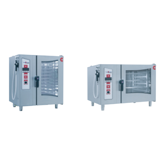
Page 10: Ogb-10.10
I I Vented, double glass door with integrated door stop and self draining condensate drip pan I I Easy to change, press-fit door seal I I Oven light with shock resistant safety glass I I Multipoint core temperature probe I I Easy to use electronic controls for all operational functions... -
Page 11: Front View
Cleveland Range reserves right of design improvement or modification, as warranted. Many regional, state and local codes exist and it is the responsibility of the owner and installer to comply with the codes. Cleveland Range equipment is built to comply with applicable standards for manufacturers. 1.82"... -
Page 12: Ogs-10.10
I I Vented, double glass door with integrated door stop and self draining condensate drip pan I I Easy to change, press-fit door seal I I Oven light with shock resistant safety glass I I Multipoint core temperature probe I I Easy to use electronic controls for all operational functions... - Page 13 Many regional, state and local codes exist and it is the responsibility of the owner and installer to comply with the codes. Cleveland Range equipment is built to comply with applicable standards for manufacturers. The "Advanced Closed System" offers the following advantages: 1.82"...
-
Page 14: Ogb-6.20
JOB NAME / NUMBER __________________________________ Short Form Specifications Shall be Cleveland Model: OGB-6.20 Combination Convection Oven / Steamer with simple to operate electronic programmable controls for Hot Air, Convection Steam, and Combination cooking modes, "Cook & Hold" and "Delta T" slow- cooking capabilities, "Advanced Closed System"... - Page 15 Cleveland Range reserves right of design improvement or modification, as warranted. Many regional, state and local codes exist and it is the responsibility of the owner and installer to comply with the codes. Cleveland Range equipment is built to comply with applicable standards for manufacturers. 1.82"...
-
Page 16: Ogs-6.20
I I Vented, double glass door with integrated door stop and self draining condensate drip pan I I Easy to change, press-fit door seal I I Oven light with shock resistant safety glass I I Multipoint core temperature probe I I Easy to use electronic controls for all operational functions... - Page 17 Cleveland Range reserves right of design improvement or modification, as warranted. Many regional, state and local codes exist and it is the responsibility of the owner and installer to comply with the codes. Cleveland Range equipment is built to comply with applicable standards for manufacturers. 1.82"...
- Page 18 1. Switch on with key (1). 2. Select cooking mode with keys (2-5). 3. Press key (6) to start. 1. Press key (18) and rotate Selector Dial (23) to set oven temperature. 2. Press key (19) and rotate Selector Dial (23) to set cooking time.
-
Page 19: B. Control Panel Detail View
• Steam generator fills and heats (OEB and OGB models). Cooking Modes 2. Steam • Oven temperature is continuously variable between 86°F and 248°F. 3. Combi Hot Air and Steam • Oven temperature is continuously variable between 212°F and 482°F. - Page 20 The timer stops. After closing the oven door, the Combi automatically continues the recipe. If the oven door is opened when the buzzer sounds at the end of a recipe, it automatically switches off. •...
-
Page 21: Cleaning The Oven Chamber
Combi oven chamber. h. Do NOT spray water into a hot oven chamber. Use only genuine Convotherm by Cleveland and Cleveland Range cleaning and descaling products. Follow the instructions and heed and obey the warnings on the labels. Other products can cause injury, present heath hazards, and damage the Combi. - Page 22 1) Release the quick-action locks on the oven racks and fan guard. 2) Pivot the oven racks and fan guard out into the oven chamber. 3) After cleaning, push the oven racks and fan guard closed and fix them in place with the quick-action locks.
- Page 23 To remove this deposit, use vinegar and a soft cloth. • Ask your qualified Cleveland Range authorized service representative about adding or setting a water treatment system. Drain Cover and Drain...
-
Page 24: Semi- Automatic Cleaning Of Oven Chamber
Release the quick-action locks on the oven racks and fan guard. b. Swing the oven racks and fan guard into the oven chamber. c. After cleaning, swing the oven racks and fan guard closed and fix it in place with the quick-action locks. - Page 25 15. Turn OFF the Combi when the Signal Tone sounds. 16. Use the hand shower to rinse thoroughly the oven chamber, accessories, and behind the fan guard. 17. In the case of severe staining or soiling, repeat the cleaning process.
-
Page 26: Convoclean Automatic Cleaning System (Optional)
B. The CONVOClean Automatic Cleaning Process 1. The oven chamber must be cold before starting this process. If the oven chamber is still hot, the error message, “oven temp too hi / please wait” appears in the display. If this error message appears, open the Combi door, wait 15 minutes and then try to start the automatic cleaning process. - Page 27 ‘Strong Soiling – Shining+” 8. Press the Smart Key. 9. “Food inside oven?” appears in the display. 10. If the oven is empty, then answer “No.” 11. Confirm by pressing the Smart Key. 12. “Start auto-cleaning?” appears in the display.
-
Page 28: Descale Steam Generator
Spent material is considered non- hazardous and may be disposed of in a sewer system with water flush. The liquid solution in Cleveland Range Descaler Solution Part No. 106174, “ can be harmful if not handled properly. - Page 29 Do NOT heat the Combi during descaling. Death, injury, equipment and property damage can result. This procedure is slightly different depending on the model being descaled. This entire procedure should be read and fully understand as it applies to the model being descaled, before beginning the actual descaling operation.
- Page 30 • While adding liquid to the steam generator through the descaler inlets, pour slowly to avoid overflow. • Wipe up any spills at once to avoid etching. 6. After the automatic fill cycle has ended, turn OFF the Combi with the ON/OFF key, and at the Control Power Service Disconnect switch located below the hand shower.
- Page 31 1010 GAS GENERATOR W CLEANING Washer Arm C2611068 Light C5005043 Light Gasket C6015020 Condensate Box o-ring C6015000 Spray Handle Shut Off Valve C6014003 Spray Handle Bracket C2002042 C6015028 Burner Chamber Seal C6015027 Flue Seal C3216313 B 0706...
- Page 32 1010 GAS GENERATOR W CLEANING I I T T E E M M Q Q T T Y Y P P A A R R T T N N 0 0 . . C2115483 C2114824 C2115490 C2114452 C2114719 C2114688 C2114743 C2114783 C2115375 C2115443...
- Page 33 1010 GAS INJ W CLEANING Washer Arm C2611068 Light Gasket C6015020 Lamp C5005043 Condensate Box o-ring C6015000 Spray Handle Bracket C2002042 Spray Handle Shut Off Valve C6014003 C3216313 B 0706...
- Page 34 1010 GAS INJ W CLEANING I I T T E E M M Q Q T T Y Y P P A A R R T T N N 0 0 . . C2115483 C2114824 C2115490 C2114452 C2114719 C2114688 C2114743 C2114783 C2115375 C2115443...
- Page 35 620 GAS GEN W CLEANING Washer Arm C2611068 Light Gasket C6015020 Lamp C5005043 Condensate Box o-ring C6015000 Spray Handle Bracket C2002042 Spray Handle Shut Off Valve C6014003 Set of racks with center support FK1119821 C3216313 B 0706...
- Page 36 620 GAS GEN W CLEANING I I T T E E M M Q Q T T Y Y P P A A R R T T N N 0 0 . . D D E E S S C C R R I I P P T T I I O O N N C2115482 ASSEMBLY, PANEL, RIGHT SIDE, 6.20 C2114826...
- Page 37 620 GAS INJ W CLEANING Washer Arm C2611068 Light gasket C6015020 Lamp C5005043 Condensate Box o-ring C6015000 Spray Handle Bracket C2002042 Spray Handle Shut Off Valve C6014003 Set of racks with center support FK1119821 C3216313 B 0706...
- Page 38 620 GAS INJ W CLEANING I I T T E E M M Q Q T T Y Y P P A A R R T T N N 0 0 . . D D E E S S C C R R I I P P T T I I O O N N C2115482 ASSEMBLY, PANEL, RIGHT SIDE, 6.20 C2114826...
- Page 39 COMPONENT PANEL ASSEMBLY, Gas OGB 6.20 & 10.10 MODELS 300480 C 0706...
- Page 40 COMPONENT PANEL ASSEMBLY, GAS OGB 6.20 & 10.10 MODELS I I T T E E M M Q Q T T Y Y P P A A R R T T N N 0 0 . . D D E E S S C C R R I I P P T T I I O O N N 300419 TRANSFORMER, 24V 111603...
- Page 41 COMPONENT PANEL ASSEMBLY, GAS OGS 6.20 & 10.10 MODELS 300488 C 0706...
- Page 42 COMPONENT PANEL ASSEMBLY, GAS OGS 6.20 & 10.10 MODELS I I T T E E M M Q Q T T Y Y P P A A R R T T N N 0 0 . . D D E E S S C C R R I I P P T T I I O O N N 300419 TRANSFORMER, 24V 111603...
- Page 43 ASSEMBLY, CONTROL PANEL, WITH PICTO ALL MODELS I I T T E E M M Q Q T T Y Y P P A A R R T T N N 0 0 . . D D E E S S C C R R I I P P T T I I O O N N C2114297 WELDMENT, CONTROL PANEL C5019101...
- Page 44 BASE, GAS, INJECTOR, WITH CLEANING OGS 10.10 MODELS Pressure Switch C5009055 Agent Pump 300352 I I T T E E M M Q Q T T Y Y P P A A R R T T N N 0 0 . . D D E E S S C C R R I I P P T T I I O O N N C5016002 LOCKNUT M25...
- Page 45 BASE, GAS, INJECTOR, NO CLEANING OGS 10.10 MODELS I I T T E E M M Q Q T T Y Y P P A A R R T T N N 0 0 . . D D E E S S C C R R I I P P T T I I O O N N C2114520 OUTER BASE, EL, 6.10/10.10 C2216088...
-
Page 46: Base, Gas Generator With Cleaning (Ogb 6.20)
BASE, GAS, GENERATOR, WITH CLEANING OGB 6.20 MODELS DETAIL A Pressure Switch C5009055 Agent Pump 300352 I I T T E E M M Q Q T T Y Y P P A A R R T T N N 0 0 . . C2114542 C2114699 C2616451... -
Page 47: Base, Gas Generator No Cleaning (Ogb 6.20)
BASE, GAS, GENERATOR, NO CLEANING OGB 6.20 MODELS DETAIL A I I T T E E M M Q Q T T Y Y P P A A R R T T N N 0 0 . . D D E E S S C C R R I I P P T T I I O O N N C2114542 ASSEMBLY, OUTER BASE, GAS, STEAM GEN, 6.20/10.20 C2016147... -
Page 48: Base, Gas Injector With Cleaning (Ogs 6.20)
BASE, GAS, INJECTOR, WITH CLEANING OGS 6.20 MODELS DETAIL A Pressure Switch C5009055 Agent Pump 300352 I I T T E E M M Q Q T T Y Y P P A A R R T T N N 0 0 . . C2114522 C2114699 C2016127... -
Page 50: All Models
ASSEMBLY, WATER HOSE SYSTEM, CONDENSER ALL MODELS Connecter Flange C5011003 I I T T E E M M Q Q T T Y Y P P A A R R T T N N 0 0 . . D D E E S S C C R R I I P P T T I I O O N N C6015215 ELBOW, HOSE CONNECTION, 3/8"... - Page 51 ASSEMBLY, WATER VALVE ALL GAS 10.10 MODELS I I T T E E M M Q Q T T Y Y P P A A R R T T N N 0 0 . . D D E E S S C C R R I I P P T T I I O O N N 300407 FILTER, ELECTRICAL 300509...
- Page 52 ASSEMBLY, WATER VALVE 10.10 MODELS I I T T E E M M Q Q T T Y Y P P A A R R T T N N 0 0 . . D D E E S S C C R R I I P P T T I I O O N N 300407 FILTER, ELECTRICAL 300509...
- Page 53 ASSEMBLY, WATER VALVE, INJECTOR, GAS OGS 6.20 & 10.10 MODELS I I T T E E M M Q Q T T Y Y P P A A R R T T N N 0 0 . . D D E E S S C C R R I I P P T T I I O O N N 300456 VALVE ASSY.
-
Page 54: Water Supply, Generator W/Cleaning System
ASSEMBLY, WATER SUPPLY, GENERATOR W/CLEANING SYSTEM OEB & OGB 6.20 MODELS I I T T E E M M Q Q T T Y Y P P A A R R T T N N 0 0 . . D D E E S S C C R R I I P P T T I I O O N N 300453 VALVE ASSEMBLY, 3WAY 240VAC 300363... - Page 55 ASSEMBLY, WATER VALVE ALL GAS 6.20 MODELS I I T T E E M M Q Q T T Y Y P P A A R R T T N N 0 0 . . D D E E S S C C R R I I P P T T I I O O N N 300456 VALVE ASSY.
- Page 56 ASSEMBLY, WATER VALVE OGS 6.20 MODELS I I T T E E M M Q Q T T Y Y P P A A R R T T N N 0 0 . . D D E E S S C C R R I I P P T T I I O O N N 300363 TRIPLE SOLENOID VALVE 110-120V 50/60 Hz 180º...
- Page 57 ASSEMBLY, STEAM GENERATOR, GAS OGB 6.20 MODELS I I T T E E M M Q Q T T Y Y P P A A R R T T N N 0 0 . . D D E E S S C C R R I I P P T T I I O O N N C2314891 WELDMENT, GEN GAS 6.20 (NOT SHOWN) C2314243...
-
Page 58: Pump, Steam Generator, Gas, 110V (All Models)
PUMP, STEAM GENERATOR, GAS, 110V ALL GAS MODELS I I T T E E M M Q Q T T Y Y P P A A R R T T N N 0 0 . . D D E E S S C C R R I I P P T T I I O O N N C6015101 C6015100 DRAIN ELBOW FOR STEAM GENERATOR... - Page 59 ASSEMBLY, BURNER INSERT, STEAM GENERATOR, NAT GAS OGB 6.20 & 10.10 MODELS I I T T E E M M Q Q T T Y Y P P A A R R T T N N 0 0 . . D D E E S S C C R R I I P P T T I I O O N N C2010045 BURNER INSERT GEN STEAM 6.10/6.20/10.10 WELDED...
-
Page 60: Burner Insert, Hl, Premounted (All Models)
BURNER INSERT, HL, PRE-MOUNTED ALL GAS MODELS I I T T E E M M Q Q T T Y Y P P A A R R T T N N 0 0 . . D D E E S S C C R R I I P P T T I I O O N N C2010050 BURNER INSERT HL, 6.10/6.20, WELDMENT C2010052... - Page 61 ASSEMBLY, BURNER INSERT, AIR, LP & NAT GAS ALL GAS MODELS I I T T E E M M Q Q T T Y Y P P A A R R T T N N 0 0 . . D D E E S S C C R R I I P P T T I I O O N N C2616521 BURNER INSERT, HL, PRE-MOUNTED, 6.10/6.20 C2616522...
-
Page 62: Door (Oes 6.20 & 10.10)
DOOR 6.20 COMPLETE OES 6.20 & 10.10 MODELS I I T T E E M M Q Q T T Y Y P P A A R R T T N N 0 0 . . D D E E S S C C R R I I P P T T I I O O N N C2514358 ASSEMBLY, OUTER DOOR, 6.20 C2514359... -
Page 63: Sliding Plate (All Models)
SLIDING PLATE, COMPLETE ALL 6.20 &10.10 MODELS Upper Hinge C2013006 I I T T E E M M Q Q T T Y Y P P A A R R T T N N 0 0 . . D D E E S S C C R R I I P P T T I I O O N N C2614806 CARRIAGE PLATE, WELDED, 6.20 C2614807... - Page 64 SLIDING PLATE, COMPLETE ALL 6.20 & 10.10 MODELS DETAIL B DETAIL C SECTION E-E DETAIL A 14 21 Page 2 of 2 19 20 SECTION D-D C2614801 B, C2614802 B & C2614804 P1 13 21 11 21 0706...
- Page 65 EXTERIOR SHEETING ALL 6.20 & 10.10 MODELS I I T T E E M M Q Q T T Y Y P P A A R R T T N N 0 0 . . D D E E S S C C R R I I P P T T I I O O N N C2514351 DOOR, 6.20, COMPLETE C2514352...
- Page 66 STAND, ASSEMBLY, CLOSED BASE 6.10 & 10.10 MODELS I I T T E E M M Q Q T T Y Y P P A A R R T T N N 0 0 . . D D E E S S C C R R I I P P T T I I O O N N C3216201 WELDMENT, STAND, COMBI, 6.10/10.10 100413...
- Page 71 ASSEMBLY, STACKING KIT, GAS MODELS 6.20 ON 6.20 OR 10.20, 6.10 ON 6.10 OR 10.10, I I T T E E M M Q Q T T Y Y P P A A R R T T N N 0 0 . . D D E E S S C C R R I I P P T T I I O O N N C3416377 WELDMENT, BASE, STACKING KIT, GAS, 6.20/10.20...
-
Page 72: Electric Models (6.10 On 6.10 Or 10.10)
ASSEMBLY, STACKING KIT, ELECTRIC MODELS 6.10 ON 6.10 OR 10.10 I I T T E E M M Q Q T T Y Y P P A A R R T T N N 0 0 . . D D E E S S C C R R I I P P T T I I O O N N C3416368 WELDMENT, BASE, STACKING KIT, ELECTRIC, 6.10/10.10 C3416362... -
Page 73: Sequence Of Operations
CLEVELAND RANGE OGB 6.20/10.10 SEQUENCE OF OPERATIONS When using these instructions refer to the OGB 6.20/10.10 wiring schematic. 1 When 120 VAC is applied to the combi, it is sent through the line filter (Z1) to the Power Control Switch (S1). - Page 74 • 120 VAC is sent from terminal 1 of connector X13 on the Control Board (A10) to the Generator Pump (M4). • As the water level drops below the probes the fill solenoid (Y3) will energize. This rocking of the water will help flush scale from the generator. •...
- Page 75 The front display will include a lighted bar under the steam symbol • When the heat circuit is energized the heat symbol will be energized • The cooking mode symbol will be energized. • The time display will invert and begin to count down. b The fan circuit is energized by the Control Board (A10) transmitting and receiving a signal from terminals 5,6,7 and 8 on connector X10 to terminals 3,4,5 and 6 of connector X28 on the Gas Board (A20)
- Page 76 5 With the combi in the Hot Air mode with time on the timer, the door closed and the start switch is depressed b The front display will include a lighted bar under the Hot Air symbol • When the heat circuit is energized the heat symbol will be energized •...
- Page 77 The heat circuit will remain energized until the cabinet set temperature is reached g When the condensate box is heated to 140 degrees F at the B3probe, 120 VAC is sent from terminal 5 of connector X12 to the condenser valve (Y1) until the temperature drops.
- Page 78 ◊ When this speed is attained the signal is sent from terminal 2 of connector X2 on the Steam Power Burner and Fan Control (U21) to terminal 9 of connector X24 on the Gas Board (A20) • A request for heat is sent from terminal 3 of connector X21 on the Gas Board (A20) to terminal 10 on connector X1 on the Steam Burner Control Module (N21) ◊...
- Page 79 ◊ In the full mode (3 drops in the display) the Y2 valve will be energized continuously. h When the timer counts to 0 or the core temp probe (B10) reaches the set amount the cycle ends and the steam generator reverts to the standby temperature of 190- degree F.
- Page 80 • A signal is sent from terminal 2 of connector X24 on the Gas Board (A20) to terminal 4 of connector X2 on the Hot Air Power Burner and Fan Control (U20) selecting the set speed of the combustion blower. ◊...
- Page 81 THIS DESIGN DESCRIBES A PROPRIETARY ITEM AND IS THE PROPERTY OF CLEVELAND RANGE. TITLE THIS DRAWING IS NOT TO BE COPIED OR USED WITHOUT THE APPROVAL OF CLEVELAND RANGE. CLEVELAND RANGE, LLC 1333 East 179th St., Cleveland, Ohio 44110-2574 VOLTAGE:...
-
Page 82: Wiring Diagram
-X10 THIS DESIGN DESCRIBES A PROPRIETARY ITEM AND IS THE PROPERTY OF CLEVELAND RANGE. TITLE THIS DRAWING IS NOT TO BE COPIED OR USED WITHOUT THE APPROVAL OF CLEVELAND RANGE. CLEVELAND RANGE, LLC 1333 East 179th St., Cleveland, Ohio 44110-2574... - Page 83 -X10:20 THIS DESIGN DESCRIBES A PROPRIETARY ITEM AND IS THE PROPERTY OF CLEVELAND RANGE. TITLE THIS DRAWING IS NOT TO BE COPIED OR USED WITHOUT THE APPROVAL OF CLEVELAND RANGE. CLEVELAND RANGE, LLC 1333 East 179th St., Cleveland, Ohio 44110-2574...
- Page 84 GM5010 THIS DESIGN DESCRIBES A PROPRIETARY ITEM AND IS THE PROPERTY OF CLEVELAND RANGE. TITLE THIS DRAWING IS NOT TO BE COPIED OR USED WITHOUT THE APPROVAL OF CLEVELAND RANGE. CLEVELAND RANGE, LLC 1333 East 179th St., Cleveland, Ohio 44110-2574...
- Page 85 BU 18 THIS DESIGN DESCRIBES A PROPRIETARY ITEM AND IS THE PROPERTY OF CLEVELAND RANGE. TITLE THIS DRAWING IS NOT TO BE COPIED OR USED WITHOUT THE APPROVAL OF CLEVELAND RANGE. CLEVELAND RANGE, LLC 1333 East 179th St., Cleveland, Ohio 44110-2574...
- Page 86 BU 18 THIS DESIGN DESCRIBES A PROPRIETARY ITEM AND IS THE PROPERTY OF CLEVELAND RANGE. TITLE THIS DRAWING IS NOT TO BE COPIED OR USED WITHOUT THE APPROVAL OF CLEVELAND RANGE. CLEVELAND RANGE, LLC 1333 East 179th St., Cleveland, Ohio 44110-2574 WIRING DIAGRAM /5.A5...
- Page 87 THIS DESIGN DESCRIBES A PROPRIETARY ITEM AND IS THE PROPERTY OF CLEVELAND RANGE. TITLE THIS DRAWING IS NOT TO BE COPIED OR USED WITHOUT THE APPROVAL OF CLEVELAND RANGE. CLEVELAND RANGE, LLC 1333 East 179th St., Cleveland, Ohio 44110-2574 VOLTAGE:...
- Page 88 THIS DESIGN DESCRIBES A PROPRIETARY ITEM AND IS THE PROPERTY OF CLEVELAND RANGE. TITLE THIS DRAWING IS NOT TO BE COPIED OR USED WITHOUT THE APPROVAL OF CLEVELAND RANGE. CLEVELAND RANGE, LLC 1333 East 179th St., Cleveland, Ohio 44110-2574 VOLTAGE:...
- Page 89 THIS DESIGN DESCRIBES A PROPRIETARY ITEM AND IS THE PROPERTY OF CLEVELAND RANGE. TITLE THIS DRAWING IS NOT TO BE COPIED OR USED WITHOUT THE APPROVAL OF CLEVELAND RANGE. CLEVELAND RANGE, LLC 1333 East 179th St., Cleveland, Ohio 44110-2574 VOLTAGE:...
-
Page 90: Sequence Of Operations
CLEVELAND RANGE OGS 6.20/10.10 SEQUENCE OF OPERATIONS When using these instructions refer to the OGS 6.20/10.10 wiring schematic. 1 When 120 VAC is applied to the combi, it is sent through the line filter (Z1) to the Power Control Switch (S1). - Page 91 • When the heat circuit is energized the heat symbol will be energized • The cooking mode symbol will be energized. • The time display will invert and begin to count down. b The fan circuit is energized by the Control Board (A10) transmitting and receiving a signal from terminals 5,6, and 7 on connector X10 to connector X12 on the Motor Drive Board (U10).
- Page 92 The front display will include a lighted bar under the Hot Air symbol • When the heat circuit is energized the heat symbol will be energized • The cooking mode symbol will be energized. • The time display will invert and begin to count down. The fan circuit is energized by the Control Board (A10) transmitting and receiving a signal from terminals 5,6, and 7 on connector X10 to connector X12 on the Motor Drive Board (U10).
- Page 93 When the timer counts to 0 or the core temp probe (B10) reaches the set amount the cycle . 5 With the combi in the Combi mode with time on the timer, the door closed and the start switch is depressed The front display will include a lighted bar under the Combi symbol •...
- Page 94 When the condensate box is heated to 140 degrees F at the B3probe, 120 VAC is sent from terminal 5 of connector X12 to the condenser valve (Y1) until the temperature drops. If the “Crisp and Tasty” mode is selected •...
- Page 95 ◊ The Hot Air Burner Control Module (N20) senses at least 1.5 micro amps DC from the flame sensor (P1) at terminal 3 of connector X2 and sends a signal from terminal 2 of connector X1 to terminal 12 of connector X15 on the Control Board (A10) •...
- Page 96 THIS DESIGN DESCRIBES A PROPRIETARY ITEM AND IS THE PROPERTY OF CLEVELAND RANGE. TITLE THIS DRAWING IS NOT TO BE COPIED OR USED WITHOUT THE APPROVAL OF CLEVELAND RANGE. CLEVELAND RANGE, LLC 1333 East 179th St., Cleveland, Ohio 44110-2574 VOLTAGE:...
-
Page 97: Wiring Diagrams
-X10 THIS DESIGN DESCRIBES A PROPRIETARY ITEM AND IS THE PROPERTY OF CLEVELAND RANGE. TITLE THIS DRAWING IS NOT TO BE COPIED OR USED WITHOUT THE APPROVAL OF CLEVELAND RANGE. CLEVELAND RANGE, LLC 1333 East 179th St., Cleveland, Ohio 44110-2574... - Page 98 -X10:20 THIS DESIGN DESCRIBES A PROPRIETARY ITEM AND IS THE PROPERTY OF CLEVELAND RANGE. TITLE THIS DRAWING IS NOT TO BE COPIED OR USED WITHOUT THE APPROVAL OF CLEVELAND RANGE. CLEVELAND RANGE, LLC 1333 East 179th St., Cleveland, Ohio 44110-2574...
- Page 99 BU 18 THIS DESIGN DESCRIBES A PROPRIETARY ITEM AND IS THE PROPERTY OF CLEVELAND RANGE. TITLE THIS DRAWING IS NOT TO BE COPIED OR USED WITHOUT THE APPROVAL OF CLEVELAND RANGE. CLEVELAND RANGE, LLC 1333 East 179th St., Cleveland, Ohio 44110-2574 WIRING DIAGRAM /3.D6...
- Page 100 THIS DESIGN DESCRIBES A PROPRIETARY ITEM AND IS THE PROPERTY OF CLEVELAND RANGE. TITLE THIS DRAWING IS NOT TO BE COPIED OR USED WITHOUT THE APPROVAL OF CLEVELAND RANGE. CLEVELAND RANGE, LLC 1333 East 179th St., Cleveland, Ohio 44110-2574 /6.A6 -A10:X15:2 /6.B5...
- Page 101 THIS DESIGN DESCRIBES A PROPRIETARY ITEM AND IS THE PROPERTY OF CLEVELAND RANGE. TITLE THIS DRAWING IS NOT TO BE COPIED OR USED WITHOUT THE APPROVAL OF CLEVELAND RANGE. CLEVELAND RANGE, LLC 1333 East 179th St., Cleveland, Ohio 44110-2574 DOOR MAGNET SWITCH...