Table of Contents
Advertisement
Quick Links
Advertisement
Table of Contents

Related Manuals for Fortec Star iBase MBB-1000


Summary of Contents for Fortec Star iBase MBB-1000
- Page 2 Manual iBase MBB-1000 ATX Motherboard with 12th Gen Intel® Core™ i9/i7/i5/i3 / Pentium® / Celeron® with Intel® R680E/ Q670E PCH The information contained in this document has been carefully researched and is, to the best of our knowledge, accurate. However, we assume no liability for any product failures or damages, immediate or consequential, resulting from the use of the information provided herein.
- Page 3 MBB-1000AF Series ® Intel Gen. Core™ DT Processor Based ATX Motherboard User’s Manual Version 1.0 (July 2022)
- Page 4 Copyright © 2022 IBASE Technology, Inc. All rights reserved. No part of this publication may be reproduced, copied, stored in a retrieval system, translated into any language or transmitted in any form or by any means, electronic, mechanical, photocopying, or otherwise, without the prior written consent of IBASE Technology, Inc.
- Page 5 Compliance This product has passed CE tests for environmental specifications and limits. This product is in accordance with the directives of the European Union (EU). In a domestic environment, this product may cause radio interference in which case users may be required to take adequate measures.
- Page 6 Important Safety Information Carefully read the precautions before using the board. Environmental conditions: Use this product in environments with ambient temperatures between 0˚C and 60˚C. Do not leave this product in an environment where the storage temperature may be below -20° C or above 80° C. To prevent from damages, the product must be used in a controlled environment.
- Page 7 Warranty Policy IBASE standard products: 24-month (2-year) warranty from the date of shipment. If the date of shipment cannot be ascertained, the product serial numbers can be used to determine the approximate shipping date. -party parts: 12-month (1-year) warranty from delivery for the 3 -party parts that are not manufactured by IBASE, such as CPU, CPU cooler, memory, storage devices, power adapter, panel and touchscreen.
-
Page 8: Table Of Contents
Table of Contents Chapter 1 General Information ..........1 Introduction ..................2 Features ....................2 Packing List ..................3 Optional Accessories ................3 Specifications ..................4 Block Diagram ..................7 Product View ..................8 Dimensions ..................10 Chapter 2 Hardware Configuration ........11 Essential Installations Before You Begin.......... - Page 9 2.5.12 24-pin ATX Power (J22) ............31 2.5.13 AT 12V Power Connector (ATX_12V_2X1) ......32 2.5.14 CPU Fan Power Connector (CPU_FAN1) ......33 2.5.15 System Fan Power Connector (SYS_FAN1,SYS_FAN2) ..34 Chapter 3 Drivers Installation ..........35 Introduction ..................36 ® Intel Chipset Software Installation Utility ...........36 VGA Driver Installation ...............38 Realtek HD Audio Driver Installation ..........40 ®...
- Page 10 This page is intentionally left blank. viii MBB-1000AF User’s Manual...
-
Page 11: Chapter 1 General Information
Chapter 1 General Information The information provided in this chapter includes: Features Packing List Optional Accessories Specifications Block Diagram Product View Board Dimensions... -
Page 12: Introduction
Introduction MBB-1000AF is an ATX motherboard based on 12th Gen Intel® Core™ i9/i7/i5/i3 and Pentium/ Celeron processors. With support for four DDR4 memory slots that accommodate up to 128GB, it features up to four independent displays with HDMI (2.0b), DVI-D, and DisplayPort (1.4) (DP++) and graphics interfaces. -
Page 13: Packing List
General Information Packing List Your MBB-1000AF package should include the items listed below. If any of the items below is missing, contact the distributor or dealer from whom you purchased the product. MBB-1000AF IO Shield SATA cable ... -
Page 14: Specifications
Specifications Model MBB-1000AF-R MBB-1000AF-Q MBB-1000AF-W Chipset Intel® R680E Intel® Q670E Intel® W680 Form Factor ATX Motherboard System Windows 10 (64-bit) Linux Fedora (64-bit) / Ubuntu (64-bit) Operating System Windows Server Intel® 12th Gen. / Core™ i / Pentium® Gold / Celeron® DT CPU Type processors CPU Socket... - Page 15 General Information Dimensions 305mm x 244mm (12” x 9.6”) RoHS 2 Certification CE, FCC Class B, LVD - LAN Wakeup Others - AT mode boot-up by jumper (via Super I/O) - SIM slot for 5G/4G/LTE I/O Ports Supports up to 4 independent displays: - HDMI 2.0b (up to 4096 x 2160 @ 60 Hz) Display - DisplayPort /DP++ (via port C, DP1.4a, up to 7680 x 4320)
- Page 16 1x PCI-E(x16) (Gen5.0) 2x PCI-E(x4) (Gen4.0) Expansion 1x PCI-E(x1) (Gen3.0) Slots 2x PCI 4x M.2 (B-Key, E-Key/ 2x M-Key) 1x M.2 (M-Key, type:2280, supports NVMe with PCI- E(x4) Gen.4 signal only) 1x M.2 (M-Key, type:2280 , supports PCIe Gen.3 & Mini Type SATA) Slots...
-
Page 17: Block Diagram
General Information Block Diagram MBB-1000AF User’s Manual... -
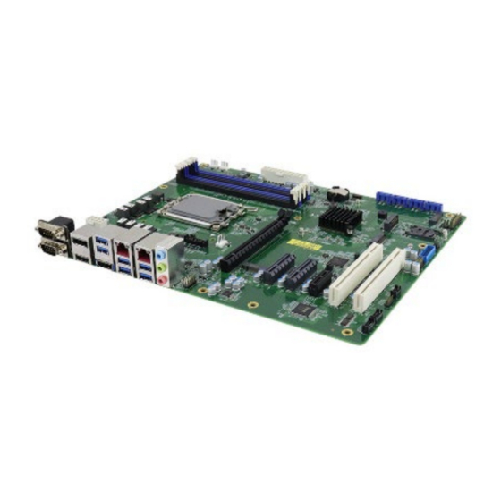
Page 18: Product View
Product View Top View MBB-1000AF MBB-1000AF User’s Manual... - Page 19 General Information I/O View Name Name COM1 RS-232/422/485 (top) Line In, Line Out, COM2 RS-232/422/485 Microphone (bottom) HDMI DisplayPort DisplayPort USB 3.1 Ports USB 3.2 Ports RJ45 for 2.5G Ethernet MBB-1000AF User’s Manual...
-
Page 20: Dimensions
Dimensions MBB-1000AF User’s Manual... -
Page 21: Chapter 2 Hardware Configuration
Chapter 2 Hardware Configuration This section provides information on jumper settings and connectors on the MBB-1000AF and other installation information in order to set up a workable system. The topics covered are: Essential installations before you begin Jumper and connector locations ... -
Page 22: Essential Installations Before You Begin
Essential Installations Before You Begin Follow the instructions below to install the memory modules. 2.1.1 Installing the Memory To install the modules, locate the memory slot on the board and perform the following steps: Align the key of the memory module with that on the memory slot and insert the module slantwise. -
Page 23: Setting The Jumpers
Hardware Configuration Setting the Jumpers Set up and configure your MBB-1000AF by using jumpers for various settings and features according to your needs and applications. Contact your supplier if you have doubts about the best configuration for your use. 2.2.1 How to Set Jumpers Jumpers are short-length conductors consisting of several metal pins with a non-conductive base mounted on the circuit board. -
Page 24: Jumper & Connector Locations
Jumper & Connector Locations MBB-1000AF MBB-1000AF User’s Manual... -
Page 25: Jumpers Quick Reference
Hardware Configuration Jumpers Quick Reference Jumper Function PCIe (x16) Bifurcation Selection Clear CMOS Data Clear RTC AT/ATX Select Sierra EM919x 5G card USB/PCIe Select Flash Descriptor Security Override (Factory use only) 2.4.1 PCIe (x16) Bifurcation Select (JP1) Function Pin closed Illustration 1 x PCIe (x16) Open... -
Page 26: Clear Cmos Data (Jp2)
2.4.2 Clear CMOS Data (JP2) Function Pin closed Illustration Normal (default) Clear CMOS 2.4.3 Clear RTC (JP3) Function Pin closed Illustration Normal (default) Clear RTC MBB-1000AF User’s Manual... -
Page 27: At / Atx Select (Jp4)
Hardware Configuration 2.4.4 AT / ATX Select (JP4) Function Pin closed Illustration Open (Default) Close MBB-100AF User’s Manual... -
Page 28: Sierra Em9191 5G Card Usb/Pcie Select (Jp5)
2.4.5 Sierra EM9191 5G Card USB/PCIe Select (JP5) Function Pin closed Illustration PCIe (default) 2.4.6 Flash Descriptor Security Override (JP6) Flash Descriptor Security Override Pin closed Illustration Disabled (default) Open Enabled Close MBB-1000AF User’s Manual... -
Page 29: Connectors Quick Reference
Hardware Configuration Connectors Quick Reference Connector Function Audio Jack 2.5G LAN (KTI225V)+ USB3.2 GEN2 #3/#4 2.5G LAN (KTI225LM) + USB3.2 GEN2 #1/#2 DisplayPort USB 3.2 #7/#8 (w/ power control) DisplayPort (upper) and HDMI (bottom) COM1 (upper) and COM2 (bottom) CN8, CN9, CN10, CN11 SATA #4, SATA #5, SATA #6, SATA #7 Front Panel Audio COM3... -
Page 30: Com1 & Com2 Rs-232/422/485 Ports (Cn7)
2.5.1 COM1 & COM2 RS-232/422/485 Ports (CN7) Signal Name RS-232 RS-422 RS-485 DATA- DATA+ Ground Ground Ground MBB-1000AF User’s Manual... -
Page 31: Front Panel Audio Connector (J1)
Hardware Configuration 2.5.2 Front Panel Audio Connector (J1) Signal Name Signal Name MIC IN_L Ground MIC IN_R LINE_R Ground Sense LINE_L Ground MBB-100AF User’s Manual... -
Page 32: Com3, Com4 Rs232 Serial Ports (J2, J3)
2.5.3 COM3, COM4 RS232 Serial Ports (J2, J3) Signal Name Signal Name DCD# SIN# SOUT RTS# DSR# DTR# CTS# Connector type: HK_DF11-10S-PA66H MBB-1000AF User’s Manual... -
Page 33: Digital I/O Connector (4 In, 4 Out) (J5)
Hardware Configuration 2.5.4 Digital I/O Connector (4 in, 4 out) (J5) Signal Name Signal Name Ground Out3 Out1 Out2 Out0 MBB-100AF User’s Manual... -
Page 34: Ps2 Keyboard/Mouse Connector (J7)
2.5.5 PS2 Keyboard/Mouse Connector (J7) Signal Name Signal Name KBDA KBCL# Connector type: HK_DF11-8S-PA66H MBB-1000AF User’s Manual... -
Page 35: Dvi-D Connector (J8)
Hardware Configuration 2.5.6 DVI-D Connector (J8) Signal Name Signal Name DATA1_P DATA1_N Ground Ground CLK_P CLK_N Ground DATA2_P DATA2_N Ground Ground DATA0_P DATA0_N Connector type: HK_DF11-20S-PA66H MBB-100AF User’s Manual... -
Page 36: Sata Connectors (Cn8, Cn9, Cn10, Cn11)
2.5.7 SATA Connectors (CN8, CN9, CN10, CN11) Signal Name Ground Ground Ground MBB-1000AF User’s Manual... -
Page 37: Usb 2.0 Connector (J10)
Hardware Configuration 2.5.8 USB 2.0 Connector (J10) Signal Name Signal Name Ground Ground MBB-100AF User’s Manual... -
Page 38: Usb 3.1 Connector (J11)
2.5.9 USB 3.1 Connector (J11) Signal Name Signal Name P1_SSRX- P1_SSRX+ P2_SSRX- P2_SSRX+ P1_SSTX- P1_SSTX+ P2_SSTX- P2_SSTX+ P1_U2_D- P1_U2_D+ P2_U2_D P2_U2_D+ Connector type: PINREX_52X-40-20GU52 MBB-1000AF User’s Manual... -
Page 39: S3 Status Connector (J19)
Hardware Configuration 2.5.10 S3 Status Connector (J19) Signal Name Signal Name 3VDUAL Ground VCC3 Ground MBB-100AF User’s Manual... -
Page 40: Front Panel Settings Connector (J20)
2.5.11 Front Panel Settings Connector (J20) Signal Name Signal Name Power LED+ Power LED- SPK(VCC) Power BTN Power BTN Reset BTN Reset BTN HDD LED+ HDD LED- MBB-1000AF User’s Manual... -
Page 41: 24-Pin Atx Power (J22)
Hardware Configuration 2.5.12 24-pin ATX Power (J22) Signal Name Signal Name 3.3V 3.3V -12V 3.3V Ground Ground PS-ON Ground Ground Ground Ground Ground Power good 5VSB +12V +12V Ground 3.3V MBB-100AF User’s Manual... -
Page 42: At 12V Power Connector (Atx_12V_2X1)
2.5.13 AT 12V Power Connector (ATX_12V_2X1) Signal Name Signal Name Ground +12V Ground +12V Ground +12V Ground +12V MBB-1000AF User’s Manual... -
Page 43: Cpu Fan Power Connector (Cpu_Fan1)
Hardware Configuration 2.5.14 CPU Fan Power Connector (CPU_FAN1) Signal Name Ground +12V Rotation detection Control Note: PWM Only MBB-100AF User’s Manual... -
Page 44: System Fan Power Connector (Sys_Fan1,Sys_Fan2)
2.5.15 System Fan Power Connector (SYS_FAN1, SYS_FAN2) Signal Name Ground +12V Rotation detection Control Note: PWM Only MBB-1000AF User’s Manual... -
Page 45: Chapter 3 Drivers Installation
Chapter 3 Drivers Installation This chapter introduces installation of the following drivers: Intel ® Chipset Software Installation Utility VGA Driver HD Audio Driver Intel ® Trusted Execution Engine Drivers Intel ® Serial I/O Drivers LAN Drivers... -
Page 46: Introduction
Introduction This section describes the installation procedures for software and drivers. The software and drivers are included with the motherboard. If you find anything missing, please contact the distributor where you made the purchase. The contents of this section include the following: Note: After installing your Windows operating system, you must install the Intel ®... - Page 47 Driver Installation ® When the Welcome screen to the Intel Chipset Device Software appears, click Next to continue. On the License Agreement screen, click Accept to continue. On the Readme File Information screen, click Install. When the driver has been completely installed, click Finish to complete the setup process.
-
Page 48: Vga Driver Installation
VGA Driver Installation Click Intel on the left pane and then Intel(R) AlderLake-S Chipset Drivers, and Intel(R) HD Graphics Driver on the right pane. When the Intel Graphics Driver Installer screen appears, click Begin installation. MBB-1000AF User’s Manual... - Page 49 Driver Installation Click I agree to accept the INTEL SOFTWARE LICENSE AGREEEMENT. In the Pre-Install stage, “The installer will install the following components: - Intel® Graphics Driver - Intel® Graphics Command Center Click Start to start installing the new graphics driver. The next screen will indicate that the new graphics driver is being installed.
-
Page 50: Realtek Hd Audio Driver Installation
Realtek HD Audio Driver Installation Click Intel on the left pane and then Intel(R) AlderLake-S Chipset Drivers, and Realtek High Definition Audio Driver on the right pane. On the Welcome screen of the InstallShield Wizard, click Next to install the drivers. When the audio driver has been successfully, click Finish to restart the computer. -
Page 51: Intel ® Me Drivers Installation
Driver Installation ® Intel ME Drivers Installation Click Intel on the left pane and then Intel(R) AlderLake-S Chipset Drivers, and Intel(R) ME Drivers on the right pane. When the Welcome screen to the Intel® Management Engine Components appears, click Next. MBB-1000AF User’s Manual... - Page 52 Accept the terms in the License Agreement and click Next. On the next screen, click Next to install to the default folder. Click Finish when the necessary components have been successfully installed. MBB-1000AF User’s Manual...
-
Page 53: Intel ® Serial Io Drivers Installation
Driver Installation ® Intel Serial IO Drivers Installation Click Intel on the left pane and then Intel(R) AlderLake-S Chipset Drivers, and Intel(R) Serial IO Drivers on the right pane. When the Welcome screen to the Intel® Serial IO appears, click Next. MBB-1000AF User’s Manual... - Page 54 Accept the terms in the license agreement and click Next. On the Readme File Information and Confirmation screens, click Next. Click Finish when the Completion screen appears. MBB-1000AF User’s Manual...
-
Page 55: Lan Drivers Installation
Driver Installation LAN Drivers Installation Click LAN Card on the left pane and then Intel PRO LAN Network Drivers on the right pane. Click Intel Drivers and Software. MBB-1000AF User’s Manual... - Page 56 When the Welcome to the install wizard for Intel(R) Nework Connection screen appears, click Next. On the next screen, accept the terms in the License Agreement and click Next. On the Setup Options screen, select the program features you want installed.
-
Page 57: Chapter 4 Bios Setup
Chapter 4 BIOS Setup This chapter describes the different settings available in the AMI BIOS that comes with the board. The topics covered in this chapter are as follows: Main Settings Advanced Settings Chipset Settings Security Settings ... -
Page 58: Introduction
4.1 Introduction The BIOS (Basic Input/Output System) installed in the ROM of your ® computer system supports Intel processors. The BIOS provides critical low-level support for standard devices such as disk drives, serial ports and parallel ports. It also provides password protection as well as special support for detailed fine-tuning of the chipset controlling the entire system. -
Page 59: Main Settings
BIOS Setup 4.3 Main Settings BIOS Setting Description Sets the date. Use the <Tab> key to switch System Date between the data elements. Set the time. Use the <Tab> key to switch System Time between the data elements. MBB-1000AF User’s Manual... -
Page 60: Advanced Settings
4.4 Advanced Settings This section allows you to configure, improve your system and allows you to set up some system features according to your preference. MBB-1000AF User’s Manual... - Page 61 BIOS Setup 4.4.1 Connectivity Configuration BIOS Setting Description This is an option intended to enable/disable RFI Mitigation DDR-RFIM feature for Connectivity This will be used to enable Preboot Bluetooth Preboot BLE function. Discrete Bluetooth SerialIo UARTO needs to be enabled to select Interface BT interace.
- Page 62 4.4.2 CPU Configuration BIOS Setting Description Intel (VMX) When enable, a VMM can utilize the additional Virtualization hardware capabilities provided by Vanderpool Technology Technology. Active Efficient-cores Number of P-cores to enable in each processor package. Note: Number of Cores Active Efficient-cores and E-cores are looked at together.
- Page 63 BIOS Setup 4.4.3 Power & Performance BIOS Setting Description Intel(R) Allows more than two frequency ranges to be SpeedStep(tm) supported. Enable/Disable Intel(R) Speed Shift Intel(R) Speed Shift Technology support. Enabling will expose the Technology CPPC v2 interface to allow for hardware controlled P-states.
- Page 64 4.4.4 PCH-FW Configuration BIOS Setting Description When Disabled ME will be put into ME ME State Temporarily Disabled Mode. Enable/Disable Intel(R) Manageability features. Manageability Note: This option disables/enables Features State Manageability Features support in FW. To disable support platform must be in an unprovisioned state first.
- Page 65 BIOS Setup 4.4.5 Trusted Computing BIOS Setting Description Enables / Disables BIOS support for security Security Device device. OS will not show security device. TCG Support EFI protocol and INTIA interface will not be available. Enables / Disables SHA256 PCR Bank. SHA256 PCR Bank Schedule an operation for the security device.
- Page 66 4.4.6 ACPI Settings BIOS Setting Description Enable ACPI Auto Enables or Disables BIOS ACPI Auto Configuration Configuration Enables / Disables the system ability to hibernate (OS/S4 Sleep State). This option may Enable Hibernation be not effective with some OS. Selects an ACPI sleep state where the system will enter when the Suspend button is pressed.
- Page 67 BIOS Setup 4.4.7 F8196x Super IO Hardware Monitor BIOS Setting Description Power Failure Options: Always on, Always off Sets parameters of Serial Ports. Enables / Disables the serial port and Serial Port Configuration select an optimal setting for the Super IO device.
- Page 68 4.4.7.2. Serial Port 2 Configuration BIOS Setting Description Serial Port Enables / Disables the serial port. Selects an optimal settings for Super I/O device. Options: Auto IO = 2F8h; IRQ = 3 Change Settings IO = 3F8h; IRQ = 3, 4, 5, 6, 7, 9, 10, 11, 12 ...
- Page 69 BIOS Setup 4.4.8 F8196x Super IO Hardware Monitor BIOS Setting Description Enables / Disables the CPU smart fan feature. CPU Smart Fan Control Options: Disabled / 50 °C / 60 °C / 70 °C / 80 °C Enables / Disables the system smart fan System Smart Fan feature.
- Page 70 4.4.9 USB Configuration BIOS Setting Description Enabled enables Legacy USB support. Auto disables legacy support if there is no Legacy USB Support USB device connected. Disabled keeps USB devices available only for EFI applications. This is a workaround for OSes without XHCI XHCI Hand-off hand-off support.
- Page 71 BIOS Setup 4.4.10 Network Stack Configuration BIOS Setting Description Network Stack Enables / Disables UEFI Network Stack. Enables / Disables IPv4 PXE Boot Support. IPv4 PXE Support If disabled, Ipv4 PXE boot option will not be created. Enables / Disables IPv4 HTTP Boot Support. IPv4 HTTP Support If disabled, Ipv4 HTTP boot option will not be created.
-
Page 72: Chipset Settings
4.5 Chipset Settings BIOS Setting Description System Agent (SA) System Agent (SA) parameters Configuration PCH-IO PCH parameters Configuration 4.5.1 System Agent (SA) Configuration BIOS Setting Description Graphics Configures the graphics settings. Configuration VMD setup meu VMD configuration settings. MBB-1000AF User’s Manual... - Page 73 BIOS Setup 4.5.1.1. Graphics Configuration BIOS Setting Description Select which of IGFX/PEG/PCI Graphics device should be primary display or select HG Primary Display for Hybrid Gfx. Options: Auto, IGFX, PEG Slot, PCH PCI, HG External Gfx Card External Gfx Card Primary Display Primary Display Configuration Configuration...
- Page 74 BIOS Setting Description GTT Size Sets the GTT size as 2 MB, 4 MB, or 8 MB. Sets the aperture size as 128 MB, 256 MB, 512 MB, 1024 MB or 2048 MB. Note: Above 4 GB MMIO BIOS assignment is Aperture Size automatically enabled when selecting 2048 MB aperture.
- Page 75 BIOS Setup 4.5.2 PCH-IO Configuration BIOS Setting Description PCH-IO PCH Parameters Configuration SATA Configuration SATA Devices Options Settings 4.5.2.1. SATA Configuration: MBB-1000AF User’s Manual...
- Page 76 BIOS Setting Description SATA Controller(s) Enables / Disables the SATA device. SATA Mode Determines how SATA controller(s) operate. Selection Serial ATA Ports Enables / Disables SATA ports. Hot Plug Designates the port as Hot Pluggable. MBB-1000AF User’s Manual...
-
Page 77: Security Settings
BIOS Setup 4.6 Security Settings BIOS Setting Description Administrator Sets an administrator password for the setup Password utility. User Password Sets a user password. Secure Boot Configures Secure Boot. 4.6.1 Secure Boot MBB-1000AF User’s Manual... - Page 78 BIOS Setting Description Secure Boot Secure Boot feature is Active if Secure Boot is enabled. Platform Key (PK) Is enrolled and the system is in User mode. The mode change requires platform reset. BIOS Setting Description Secure Boot Mode Secure Boot mode options: Standard or Custom.
- Page 79 BIOS Setup MBB-1000AF User’s Manual...
-
Page 80: Boot Settings
4.7 Boot Settings BIOS Setting Description Number of seconds to wait for setup activation Setup Prompt key. Timeout 65535(0xFFFF) means indefinite waiting. Bootup NumLock Selects the keyboard NumLock state. State Quiet Boot Enables / Disables Quiet Boot option. Boot mode select Selects a Boot mode, Legacy / UEFI. -
Page 81: Save & Exit Settings
BIOS Setup 4.8 Save & Exit Settings BIOS Setting Description Save Changes and Exits system setup after saving the changes. Exit Discard Changes Exits system setup without saving any and Exit changes. Save Changes and Resets the system after saving the changes. Reset Discard Changes Resets system setup without saving any... - Page 82 This page is intentionally left blank. MBB-1000AF User’s Manual...
-
Page 83: Appendix
Appendix This section provides the mapping addresses of peripheral devices and the sample code of watchdog timer configuration. -
Page 84: I/O Port Address Map
I/O Port Address Map Each peripheral device in the system is assigned a set of I/O port addresses which also becomes the identity of the device. The following table lists the I/O port addresses used. Address Device Description 0x00000A00-0x00000A0F Motherboard resources 0x00000A10-0x00000A1F Motherboard resources 0x00000A20-0x00000A2F... - Page 85 Appendix Address Device Description 0x000000A4-0x000000A5 Programmable interrupt controller 0x000000A8-0x000000A9 Programmable interrupt controller 0x000000AC-0x000000AD Programmable interrupt controller 0x000000B0-0x000000B1 Programmable interrupt controller 0x000000B4-0x000000B5 Programmable interrupt controller 0x000000B8-0x000000B9 Programmable interrupt controller 0x000000BC-0x000000BD Programmable interrupt controller 0x000004D0-0x000004D1 Programmable interrupt controller 0x000003F8-0x000003FF Communications Port (COM1) 0x000002F8-0x000002FF Communications Port (COM2) 0x000003E8-0x000003EF...
-
Page 86: Interrupt Request Lines (Irq)
Interrupt Request Lines (IRQ) Peripheral devices use interrupt request lines to notify CPU for the service required. The following table shows the IRQ used by the devices on board. Level Function IRQ 0 System timer IRQ 1 Standard PS/2 Mouse IRQ 3 Communications Port (COM2) IRQ 4... - Page 87 Appendix Level Function Intel(R) Ethernet Controller (3) I225-V 4294967254~70 Intel(R) Ethernet Controller (3) I225-LM 4294967271~87 IRQ 4294967288 Intel(R) Management Engine Interface #1 IRQ 4294967289 Intel(R) UHD Graphics 770 Intel(R) USB 3.20 eXtensible Host Controller IRQ 4294967290 - 1.20 (Microsoft) IRQ 4294967291 Standard SATA AHCI Controller IRQ 4294967292 Intel(R) PCI Express Root Port #5 - 7ABC...
-
Page 88: Watchdog Timer Configuration
Watchdog Timer Configuration The Watchdog Timer (WDT) is used to generate a variety of output signals after a user programmable count. The WDT is suitable for use in the prevention of system lock-up, such as when software becomes trapped in a deadlock. - Page 89 Appendix bTime = strtol (argv[1], endptr, 10); printf("System will reset after %d seconds\n", bTime); if (bTime) EnableWDT(bTime); } else DisableWDT(); } return 0; //--------------------------------------------------------------------------- void EnableWDT(int interval) unsigned char bBuf; bBuf = Get_F81966_Reg(0x2B); bBuf &= (~0x20); Set_F81966_Reg(0x2B, bBuf); //Enable WDTO Set_F81966_LD(0x07);...
- Page 90 //--------------------------------------------------------------------------- // THIS CODE AND INFORMATION IS PROVIDED "AS IS" WITHOUT WARRANTY OF ANY // KIND, EITHER EXPRESSED OR IMPLIED, INCLUDING BUT NOT LIMITED TO THE // IMPLIED WARRANTIES OF MERCHANTABILITY AND/OR FITNESS FOR A PARTICULAR // PURPOSE. //--------------------------------------------------------------------------- #include "F81966.H" #include <dos.h>...
- Page 91 Appendix Lock_F81966(); //--------------------------------------------------------------------------- void Set_F81966_Reg( unsigned char REG, unsigned char DATA) Unlock_F81966(); outportb(F81966_INDEX_PORT, REG); outportb(F81966_DATA_PORT, DATA); Lock_F81966(); //--------------------------------------------------------------------------- unsigned char Get_F81966_Reg(unsigned char REG) unsigned char Result; Unlock_F81966(); outportb(F81966_INDEX_PORT, REG); Result = inportb(F81966_DATA_PORT); Lock_F81966(); return Result; //--------------------------------------------------------------------------- //--------------------------------------------------------------------------- // THIS CODE AND INFORMATION IS PROVIDED "AS IS" WITHOUT WARRANTY OF ANY // KIND, EITHER EXPRESSED OR IMPLIED, INCLUDING BUT NOT LIMITED TO THE // IMPLIED WARRANTIES OF MERCHANTABILITY AND/OR FITNESS FOR A PARTICULAR // PURPOSE.
-
Page 92: Onboard Connector Types
Onboard Connector Types Compatible Function Connector Type Mating Type (for reference) DVI-D HK_DF11-20S-PA66H COM1 & YIMTEX COM2 RS- D-SUB 9-pin 40909AANSABR 232/422/485 Dupont Front Panel E-call 2.54 mm 2*5- Audio 0126-01-2821009 Dupont Digital I/O E-call 2.0 mm 2*5- Connector 0196-01-200-100 COM3, COM4 J2 (COM3) HAOGUO... -
Page 93: Mbb1000 Usb Power Control Bit Mapping
Appendix MBB1000 USB Power Control Bit Mapping. Function Connector Software Mapping M.2 –E Key bit_0 USB3.1 CN5(A,B) bit_1 MBB-1000AF User’s Manual... - Page 94 Our company network supports you worldwide with offices in Germany, Austria, Switzerland, the UK and the USA. For more information please contact: Headquarters Germany FORTEC Elektronik AG Augsburger Str. 2b 82110 Germering Phone: +49 89 894450-0 E-Mail: info@fortecag.de Internet: www.fortecag.de Fortec Group Members Austria Distec GmbH Office Vienna...