Table of Contents
Advertisement
Quick Links
Advertisement
Table of Contents

Related Manuals for Panasonic AW-RP60GJS


Summary of Contents for Panasonic AW-RP60GJS
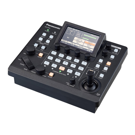
- Page 1 Operating Instructions Remote Camera Controller AW-RP60G Model No. Before operating this product, please read the instructions carefully and save this manual for future use. Please carefully read the “Read this first!” (pages 3 to 4) of this Manual before use. ENGLISH W1019GU2120 -FJ DVQP2093XA...
- Page 2 اﻟﻌرﺑﯾﺔ A termékkel kapcsolatos biztonsági információkért .اﻟﮭﺎﻣﺔ ﺑﺷﺄن اﻟﻣﻧﺗﺞ Magyar és fontos értesítésekért látogasson el az alábbi weboldalra. https://pro‑av.panasonic.net/manual/en/index.html Furthermore, the product numbers of equipment are referred to as About trademarks and registered trademarks follows. z Microsoft ® , Windows ®...
-
Page 3: Read This First
FCC NOTICE (USA) Supplier’s Declaration of Conformity Model Number: AW‑RP60G Trade Name: Panasonic Responsible Party: Panasonic Corporation of North America Two Riverfront Plaza, Newark, NJ 07102 Support contact: 1‑800‑524‑1448 This device complies with part 15 of the FCC Rules. Operation is subject to the following two conditions: (1) This device may not cause harmful interference, and (2) this device must accept any interference received, including interference that may cause undesired operation. - Page 4 For more information about collection and recycling, please contact your local municipality, dealer or supplier. Penalties may be applicable for incorrect disposal of this waste, in accordance with national legislation. Manufactured by: Panasonic Corporation, Osaka, Japan Importer’s name and address of pursuant to EU rules:...
-
Page 5: Table Of Contents
Contents Read this first! ......................3 Introduction . -
Page 6: Introduction
It is your responsibility to take sufficient network security measures such https://pro‑av.panasonic.net/ as those described below to protect yourself against the above risks. Panasonic does not accept any responsibility for damage of this type. „ Disclaimer of warranty z Use this unit in a network secured by a firewall, etc. -
Page 7: Precautions For Use
Precautions for use Observe the following in addition to the information included in “Read this first!”. Handle carefully LCD panels Do not drop the product, or subject it to a strong impact or vibration. The pixels of the LCD panel are controlled to obtain high precision with Do not carry or move the product by the PAN/TILT lever or a dial. -
Page 8: Precautions For Installation
Precautions for installation In addition to the safety precautions given in “Read this first!”, also observe the following instructions. Be sure to ask your dealer to perform the installation and connection work for the unit. Connecting a power supply Do not allow any foreign objects to enter inside the unit z Insert the DC plug for the external DC power supply all the way in z Allowing water, metal items, food or drink, or other foreign objects to until it locks into place. -
Page 9: Features
*2: Power over Ethernet. Referred to as “PoE” in this manual. *3: For details on PoE power supply devices for which operation has been verified, consult your local dealer. Supported remote cameras z Integrated Camera AW‑HE35, AW‑HE38, AW‑HE40, AW‑HE42, AW‑HN38, AW‑HN40, AW‑UE70, AW‑UN70 For details, visit the following website. https://pro‑av.panasonic.net/... -
Page 10: Parts And Their Functions
Parts and their functions Control panel CAMERA OSD Menu operation section POWER ALARM SELECT ON/OFF MENU BARS EXIT Color adjustment STORE DELETE section USER 1 USER 2 PRESET User button section USER 3 USER 4 Preset memory PRESET MEMORY SELECTION selection section ENABLE... - Page 11 Parts and their functions (continued) Camera selection section Pan and tilt section ENABLE CAMERA SELECTION Camera selection buttons [CAMERA SELECTION 1 to 5] Use these to select the camera number belonging to the camera group that was set on the status screen.
- Page 12 Parts and their functions (continued) C Auto focus button [FOCUS AUTO] Focus, zoom and iris section Use this to set focus control to “Auto (auto focus)”. During auto focusing, operation of the FOCUS dial ( ) and one‑touch auto focus button ( ) is disabled. ...
- Page 13 Parts and their functions (continued) I Preset memory selection buttons Color adjustment section [PRESET MEMORY SELECTION 1 to 10] Use these to recall the preset of the preset group that was set on the status screen. STORE button () is lit: BARS Use these to register the number of the preset in the preset group that was set in the status screen.
-
Page 14: Rear Panel
Parts and their functions (continued) Rear panel POWER SIGNAL GND TALLY/GPIO SERIAL CONT IP CONT 12 V RS-422 DC IN socket [12V IN] (DC 12 V) (XLR connector) Grounding terminal [SIGNAL GND] Connect an external DC power supply to this connector. -
Page 15: Connections
Connections Examples of IP connections „ IP connections for remote cameras „ AW‑UE70 AW‑UE70* connector AC adaptor SDI video LAN cables signals (Straight cable or cross cable) Max. 100 m (328 ft) Monitor 2 AC adaptor Monitor 1 Switching hub LAN cable (Straight cable or cross cable) - Page 16 Connections (continued) „ IP connections for multiple units and remote cameras „ AW‑UE70 AW‑UE70 * AC adaptor LAN cables PoE+ supported switching hub or (Straight cable or cross cable) PoE+ injector * Max. 100 m (328 ft) External DC External DC External DC External DC External DC...
-
Page 17: Examples Of Serial Connections
Connections (continued) Examples of serial connections „ Serial connections for remote cameras „ AW‑UE70 AW‑UE70* RS‑422 connector AC adaptor Serial control signals LAN cables (Straight cable) Max. 1000 m (3280 ft) SDI video signals Monitor 1 Monitor 2 Monitor Monitor Switcher External DC power supply... -
Page 18: Basic Operations Of The Unit
Basic operations of the unit Turn on the unit’s power. Adjust the lens iris. Set the POWER switch to the ON position. When the PAN/TILT / IRIS / ZOOM / FOCUS ENABLE button Power is supplied to the unit, and the POWER indicator turns on. [ENABLE] indicator is on (amber), turn the IRIS dial to adjust the z When the [AUTO POWER] item in the [CAMERA] SYSTEM menu lens iris. -
Page 19: How To Turn On And Off The Power Of The Remote Cameras
How to turn on and off the power of the remote cameras How to turn on the power of the remote Turning on the power of the cameras simultaneously with the turning on of the unit’s power cameras Press the [MENU] button. The power of the remote cameras in the standby state can be turned on from the unit. -
Page 20: How To Turn Off The Power Of The Remote Cameras
How to turn on and off the power of the remote cameras (continued) How to turn off the power of the remote Turning off the power of multiple cameras cameras Press the [MENU] button. The power of the remote cameras can be turned off from the unit. Select the [CAMERA] SYSTEM menu to display the There are the following methods of turning off the power. -
Page 21: Selecting A Camera Group
Selecting a camera group This unit allows you to register up to 200 remote cameras as control Selecting a camera group targets by configuring the connection settings for each of the camera numbers CAM1 to CAM200. To select a remote camera to control from Press the F2 dial on the status screen. -
Page 22: Selecting A Remote Camera
Selecting a remote camera You can press a camera selection button [CAMERA SELECTION] to select the remote camera to control. When a camera selection button is pressed, the indicator of the pressed button turns on and the remote camera is selected. The status of the lamp (camera status LED) below each button indicates the status of the remote camera that is allocated to the camera selection button [1] to [5]. -
Page 23: Status Screen
Status screen Displaying and operating the status screen The status screen is displayed as the initial display when the power of the unit is turned on to start it up. The status screen displays the following information. z Camera number z Information about allocations to USER buttons z IRIS, ZOOM, and FOCUS position Display... -
Page 24: Basic Operations For The Menus
Basic operations for the menus Displaying menus and the menu configuration Use the [MENU] button and LCD panel on the unit to operate the menus. Follow the procedure below to display the menu. The menu is displayed on the LCD panel (A) of the unit. CAMERA OSD UE70 ALARM... - Page 25 Basic operations for the menus (continued) Operating procedure Press the [MENU] button to display the MENU screen. For details, refer to “Menu group” (page 37). z Pressing the [MENU] button again will turn the menu display off and status screen is displayed. CAMERA OSD UE70 POWER...
- Page 26 Basic operations for the menus (continued) Turn the [F5] dial to find the item you want to set and then press the [F5] dial to select the menu. CAMERA OSD UE70 PAINT 101 SCENE POWER ALARM 102 SHUTTER SELECT 103 CROMA 104 GAIN 105 WHITE BALANCE 106 GAMMA...
-
Page 27: Network Settings Of The Unit
Network settings of the unit To control a remote camera connected via an IP connection from the Setting the subnet mask unit, you need to set the network settings of the unit. Note Press the [MENU] button. z Correct operation is not possible if the same IP address already exists in the same network. - Page 28 Network settings of the unit (continued) Setting the default gateway Displaying the MAC address Press the [MENU] button. Press the [MENU] button. Select the [RP IP SET] SYSTEM menu. Select the [RP IP SET] SYSTEM menu. Operate the menu operation dials to select the Operate the menu operation dials to select the [MAC [GATEWAY] item and then press to confirm.
-
Page 29: Settings For Connecting With The Remote Cameras
Settings for connecting with the remote cameras To control remote cameras from the unit and use the function to link the Overview of related menus and operations unit, you need to set the connection settings in advance. There are two ways of configuring the connection settings. You can [SYSTEM] >... -
Page 30: Setting The Connection Types (Serial/Ip/No Connection) For Remote Cameras
Settings for connecting with the remote cameras (continued) Setting the connection types (serial/IP/ Setting the IP addresses automatically no connection) for remote cameras (auto IP setting) Set the connection types for camera numbers CAM1 to When “auto IP setting” is executed, the settings for linking between the remote cameras connected within the same subnet as the unit are CAM200. - Page 31 Settings for connecting with the remote cameras (continued) Turn the [EXEC] (F4 dial) to select [SETTING], then 192.168.0.10 press the F4 dial. 192.168.0.11 “Auto IP setting” starts. 192.168.0.10 The “AUTO IP SETTING” message is displayed while “auto IP 192.168.0.10 ...
- Page 32 Settings for connecting with the remote cameras (continued) When introducing additional remote cameras into an environment in which IP connections are already in Remote camera B Remote The settings can be configured using “auto IP setting” even when Remote camera C camera A introducing additional remote cameras into an environment in which IP connections are already in use.
- Page 33 Settings for connecting with the remote cameras (continued) Set [EXEC] (F4 dial) to [SETTING], then press the F4 Example: dial. (1) Operation is being performed with the three remote cameras A, B “Auto IP setting” starts. and C set to CAM1, CAM2 and CAM3, respectively. The “AUTO IP SETTING”...
- Page 34 Settings for connecting with the remote cameras (continued) <Operating procedure> Connect the additional remote cameras to be introduced Connection device detection and the unit to the network within the same subnet. z When the number of new devices detected by [RENEW] or [KEEP] Select the [AUTO IP SET] SYSTEM menu, turn the F1 exceeds the number of devices that can be registered (200 remote dial to display [KEEP], then press the F1 dial.
-
Page 35: Manually Setting The Connection Destination Ip Addresses (Remote Cameras) And Port Number
Settings for connecting with the remote cameras (continued) „ Settable port numbers Manually setting the connection destination „ IP addresses (remote cameras) and port You can set a value within the range of 1 to 65535. However, the following values cannot be set even though they are within number this range. -
Page 36: Initializing The Connection Destination Ip Addresses Set On The Unit
Settings for connecting with the remote cameras (continued) Initializing the connection destination IP addresses set on the unit Use the following procedure to initialize the connection types and connection destination IP addresses set on the unit. Select the [RP INITIALIZE] MAINTENANCE menu. Operate the menu operation dials to select [INIT ALL] and press to confirm. -
Page 37: Menu
Menu Menu group ⇒ “SCENE” (page 38) PAINT SCENE ⇒ “SHUTTER” (page 39) SHUTTER ⇒ “CHROMA” (page 39) CHROMA ⇒ “GAIN” (page 40) GAIN ⇒ “WHITE BALANCE” (page 40) WHITE BALANCE ⇒ “GAMMA” (page 41) GAMMA ⇒ “DRS” (page 41) ⇒... -
Page 38: Paint
Menu (continued) PAINT ⇒ “SCENE” (page 38) ⇒ “SHUTTER” (page 39) ⇒ “CHROMA” (page 39) ⇒ “GAIN” (page 40) ⇒ “WHITE BALANCE” (page 40) ⇒ “GAMMA” (page 41) ⇒ “DRS” (page 41) ⇒ “DTL” (page 42) ⇒ “COLOR CORRECT” (page 42) ⇒... - Page 39 Menu (continued) „ SHUTTER „ z The setting values and available setting items depend on the connected camera. AW-UE70 SHUTTER MODE SPEED ー Item Setting details MODE Select for camera shutter mode. SPEED Select the shutter speed for the camera. „...
- Page 40 Menu (continued) „ GAIN „ z The setting values and available setting items depend on the connected camera. AW-UE70 GAIN GAIN AGC MAX AUTO 24dB Item Setting details GAIN The image gain is adjusted here. In locations which are too dark, adjust the gain upward; conversely, in locations which are too bright, adjust it downward. AGC MAX When [AUTO] is selected as the [GAIN] setting, the maximum gain‑up amount can be set.
- Page 41 Menu (continued) „ GAMMA „ z The setting values and available setting items depend on the connected camera. AW-UE70 GAMMA TYPE LEVEL NORMAL Item Setting details TYPE Select the type of gamma curve. LEVEL Adjust the gamma correction level. Specifying smaller values results in a gentler gamma curve for the slope of low‑brightness areas and sharper contrast. Specifying larger values results in an expanded gradient for dark areas and produces brighter images.
- Page 42 Menu (continued) „ DTL „ z The setting values and available setting items depend on the connected camera. AW-UE70 FLESH H LEVEL L LEVEL TONE 9 Item Setting details Adjust the contour correction level (master). H LEVEL Adjusts the contour correction level when [DTL] is set to [HIGH]. L LEVEL Adjusts the contour correction level when [DTL] is set to [LOW].
- Page 43 Menu (continued) AW-UE70 COLOR CORRECT PHASE PHASE B_Mg_Mg B_Mg_Mg PHASE PHASE Mg_R Mg_R PHASE PHASE R_R_Yl R_R_Yl R_YI_Yl R_Yl_Yl AW-UE70 COLOR CORRECT PHASE PHASE Yl_Yl_G Yl_Yl_G PHASE PHASE Yl_G_G Yl_G_G PHASE PHASE G_Cy G_Cy Cy_B_B Cy_B_B Item Setting details TYPE Select the type of color matrix.
- Page 44 Menu (continued) Item Setting details SAT Yl_G_G Adjusts the color saturation with a 1:3 yellow to green ratio. PHASE Yl_G_G Adjusts the hue with a 1:3 yellow to green ratio. SAT G Adjust the saturation of green. PHASE G Adjust the hue of green. SAT G_Cy Adjust the saturation of the color between green and cyan.
- Page 45 Menu (continued) „ PEDESTAL „ z The setting values and available setting items depend on the connected camera. AW-UE70 PEDESTAL M.PED Item Setting details M.PED Use this to adjust the master pedestal. „ CONTRAST „ z The setting values and available setting items depend on the connected camera. AW-UE70 CONTRAST MODE...
-
Page 46: Function
Menu (continued) FUNCTION ⇒ “USER ASSIGN” (page 46) ⇒ “CAMERA INFO” (page 48) ⇒ “PTZ INFO1” (page 49) ⇒ “PTZ INFO2” (page 50) ⇒ “HOUSING” (page 51) ⇒ “CROP” (page 52) „ USER ASSIGN „ AW-UE70 USER ASSIGN USER1 USER2 USER3 USER4 I.S. - Page 47 Menu (continued) Item Initial setting Setting details USER1 I.S. It is possible to allocate the following functions to the user buttons. USER2 POWER OFF: D. HAZE: Power off function D.HAZE CLR SW On/Off function (This feature is USER3 ND1, ND2, ND3, ND4: available when connected to a camera for business USER4 ND1 to ND4 functions...
- Page 48 Menu (continued) „ CAMERA INFO „ z The setting values and available setting items depend on the connected camera. AW-UE70 CAMERA INFO D.ZOOM D.ZOOM D.EXT I.S. BARS TYP TYPE2 AW-UE70 CAMERA INFO OSD STAT AUDIO GENLOCK ー BK LIGHT Item Setting details Set the ND filter.
- Page 49 Menu (continued) „ PTZ INFO1 „ z The setting values and available setting items depend on the connected camera. AW-UE70 PTZ INFO1 SPEED ZOOM FREEZE WTH Z MIN SPD LIMIT LIMIT LIMIT LIMIT DOWN LEFT RIGHT FOCUS/ CURVE IRIS STNDRD Item Setting details SPEED WTH Z...
- Page 50 Menu (continued) „ PTZ INFO2 „ AW-UE70 PTZ INFO2 CAM SEL CAM1 TILT ZOOM FOCUS NORMAL NORMAL NORMAL NORMAL IRIS NORMAL Item Setting details CAM SEL Settings can be made for rows from the second and so on for the selected camera number. PAN DIR Set the operating direction for the remote camera with the pan operation.
- Page 51 Menu (continued) „ HOUSING „ (For future expansion feature. This function is available when connecting a camera which is equipped with the HOUSING function.) z The setting values and available setting items depend on the connected camera. AW-UE70 HOUSING HEATER DEFROSTER WIPER ー...
- Page 52 Menu (continued) „ CROP „ (For future expansion feature. This function is available when connecting a camera which is equipped with the CROP function.) z The setting values and available setting items depend on the connected camera. AW-UE70 CROP ADJUST H POS V POS ー...
-
Page 53: Maintenance
Menu (continued) MAINTENANCE ⇒ “RP SETTING” (page 53) ⇒ “RP INITIALIZE” (page 54) ⇒ “RP VERSION” (page 55) ⇒ “GPI TALLY” (page 56) ⇒ “GPIO CAM SEL” (page 57) ⇒ “GPO CAM.G” (page 59) ⇒ “GPI PMEM” (page 60) ⇒ “GPI PMEM.G” (page 61) „... - Page 54 Menu (continued) Item Setting value Setting details MENU BT MODE PMEM OFF You can enable or disable the PMEM button when the MENU button on the LCD panel is set to ON. PMEM OFF: PMEM ON This disables the PMEM function when MENU is set to ON and is used for the button to select the menu in the first layer.
- Page 55 Menu (continued) „ RP VERSION „ AW-UE70 RP VERSION SYSTEM VERSION 1.00-00-0.00 SOFT VERSION FPGA VERSION 1.00-00-0.00 1.00-00-0.00 Item Setting value Setting details SYSTEM VERSION – Displays the system version for the unit. SOFT VERSION – Displays the software version. FPGA VERSION –...
- Page 56 Menu (continued) „ GPI TALLY „ AW-UE70 GPI TALLY TALLY TALLY1 TALLY2 TALLY3 TALLY4 CAM1 CAM2 CAM3 CAM4 TALLY5 CAM5 ___ indicates factory default settings. Item Setting value Setting details TALLY OUT Set whether to send a TALLY notification to the camera if TALLY is input through the port of the TALLY/GPIO connector.
- Page 57 Menu (continued) „ GPIO CAM SEL „ AW-UE70 GPIO CAM SEL CAM1 CAM2 CAM3 CAM4 CAM5 OUT1 OUT2 OUT3 OUT4 CAM1 CAM2 CAM3 CAM4 AW-UE70 GPIO CAM SEL OUT5 CAM5 ___ indicates factory default settings. Item Setting value Setting details CAM1 Select the camera to be switched when there is CAMERA_SELECT_IN1 input through the port of the TALLY/GPIO connector.
- Page 58 Menu (continued) Item Setting value Setting details OUT2 CAM1 Notification is sent to CAMERA_SELECT_OUT2 of the port of the TALLY/GPIO connector when the CAM2 set camera is selected. ⁞ CAM200 OUT3 CAM1 Notification is sent to CAMERA_SELECT_OUT3 of the port of the TALLY/GPIO connector when the set camera is selected.
- Page 59 Menu (continued) „ GPO CAM.G „ AW-UE70 GPO CAM.G OUT1 OUT2 OUT3 OUT4 GROUP1 GROUP2 GROUP3 GROUP4 OUT5 OUT6 OUT7 OUT8 GROUP5 GROUP6 GROUP7 GROUP8 ___ indicates factory default settings. Item Setting value Setting details OUT1 GROUP1 Displays the camera group set for the CAM_GRP_SEL OUT1 terminal of the port for the TALLY/GPIO connector.
- Page 60 Menu (continued) „ GPI PMEM „ AW-UE70 GPI PMEM PMEM1 PMEM2 PMEM3 PMEM4 PMEM5 PMEM6 PMEM7 PMEM8 IN10 PMEM9 PMEM10 ___ indicates factory default settings. Item Setting value Setting details PMEM1 With the TALLY/GPIO connector, playback of the set preset number is performed when there is input through PRESET_SELECT_IN1.
- Page 61 Menu (continued) „ GPI PMEM.G „ AW-UE70 GPI PMEM.G GPI IN PMEM MODE SEPARATE SEL2 SEL1 SEL1 SEL2 CAM1 PMEM1 CAM2 PMEM1 SEL3 SEL3 SEL4 SEL4 CAM3 PMEM1 CAM4 PMEM1 AW-UE70 GPI PMEM.G SEL5 SEL5 SEL6 SEL6 CAM5 PMEM1 CAM6 PMEM1 SEL7 SEL7...
- Page 62 Menu (continued) Item Setting value Setting details SEL3 CAM CAM1 Select the camera number to playback. ⁞ CAM3 ⁞ CAM200 SEL3 PM PMEM1 Allocate the preset playback number to the camera selected with SEL3 CAM. ⁞ PMEM100 SEL4 CAM CAM1 Select the camera number to playback.
-
Page 63: Pmem
Menu (continued) PMEM „ Operating preset memory (PMEM) „ The preset memory of a remote camera can be operated from the unit. The following settings that you have adjusted in advance can be stored in preset memory. z Pan/tilt positions z Lens iris settings (manual iris only) z Zoom positions z White balance settings... - Page 64 Menu (continued) „ PMEM LIST „ z You can view the preset memory registration status for the selected remote camera and play back preset memories by selecting preset numbers. AW-UE70 PMEM LIST PMEM1 PMEM2 PMEM3 PMEM4 PMEM5 PMEM6 PMEM7 PMEM8 PMEM9 PMEM10 PMEM11...
- Page 65 Menu (continued) „ SETTING „ z Make basic settings for preset memory. The setting values and available setting items depend on the connected camera. AW-UE70 SETTING RP CTRL SCOPE HOME SPD MODE CAMERA SPEED SPEED SPEED UNIT SLOW STEP ZOOM D-EXT CROP MODE...
- Page 66 Menu (continued) Item Setting value Setting details SPEED (Setting on the The movement speed or time up to the preset position is displayed. remote camera) When the [SPEED UNIT] is [STEP], this displays the speed of movement to the preset position. When it is [TIME], this displays the time it will take to move to the preset position.
-
Page 67: System
Menu (continued) SYSTEM ⇒ “CAMERA” (page 67) ⇒ “CONNECT SETTING” (page 68) ⇒ “MANUAL IP SET/USER AUTH” (page 69) ⇒ “AUTO IP SET” (page 70) ⇒ “RP IP SET” (page 71) ⇒ “TRACKING” (page 72) „ CAMERA „ AW-UE70 CAMERA AUTO POWER POWER... - Page 68 Menu (continued) „ CONNECT SETTING „ AW-UE70 CONNECT SETTING 1/17 CONNECT CAM SEL MODE CAM1 Serial CAM1 CAM2 CAM3 CAM4 Serial CAM5 CAM6 CAM7 CAM8 AW-UE70 CONNECT SETTING 17/17 CAM189 CAM190 CAM191 CAM192 CAM193 CAM194 CAM195 CAM196 CAM197 CAM198 CAM199 CAM200 ___ indicates factory default settings.
- Page 69 Menu (continued) „ MANUAL IP SET/USER AUTH „ AW-UE70 MANUAL IP SET/USER AUTH CAM SEL CAM1 CAM IP PORT SAVE (push) AW-UE70 MANUAL IP SET/USER AUTH USER NAME PASSWORD RETYPE PASSWORD SAVE ___ indicates factory default settings. Item Setting value Setting details CAM SEL CAM1...
- Page 70 Menu (continued) „ AUTO IP SET „ AW-UE70 AUTO IP SET AUTO SET TOTAL EXEC RENEW ___ indicates factory default settings. Item Setting value Setting details AUTO SET NON: RENEW No search is made for remote cameras. KEEP RENEW: The unit first searches within the same subnet. After this, each detected remote camera is allocated a camera number in order.
- Page 71 Menu (continued) „ RP IP SET „ AW-UE70 RP IP SET NETWORK SAVE SETTING STATIC (push) SUBNET AW-UE70 RP IP SET GATEWAY PORT PORT PORT PORT 61000 61002 61004 61006 PORT 61008 AW-UE70 RP IP SET MAC ADDRESS **-**-**-**-**-** ___ indicates factory default settings. Item Setting value Setting details...
- Page 72 Menu (continued) Item Setting value Setting details GATEWAY 192.168.0.1 Sets the default gateway of the unit. PORT C1 61000 It is possible to allocate reception port numbers for each camera selection button. PORT C2 61002 PORT C3 61004 PORT C4 61006 PORT C5 61008...
-
Page 73: Setup Software
This section describes how to install Setup Software. You can obtain the software from the Service and Support page of the following website. https://pro‑av.panasonic.net/ Download the Setup Software zip file from the Service and Support page of the website. Double‑click the downloaded zip file to decompress the file. -
Page 74: Settings For Connecting With The Remote Cameras
Setup Software (continued) The screens of Windows 10 are used in the explanations in this manual. If you are using an operating system other than Windows 10, some of the items displayed on the screens may differ. Settings for connecting with the remote cameras z When connecting with the remote camera, select [MAINTENANCE] >... - Page 75 Setup Software (continued) MAC ADDRESS Displays the MAC addresses of remote cameras with links set with camera numbers of this unit. z These are displayed when they are acquired with [AUTO IP SET] on the main unit or with [AUTO IP CAM ASSIGN] on this software. IP ADDRESS Set the IP address of the remote camera that will be the connection destination.
- Page 76 Setup Software (continued) Displaying the [Auto IP Cam Assign] tab When a [NETWORK SEARCH] is executed and applicable remote cameras are found, they are displayed in a list. The list shows then in the order they were found. CAMERA NAME The camera names found in the search are displayed.
- Page 77 Setup Software (continued) Displaying the [Preset Name] tab You can set a name of up to 8 characters for a preset number. Camera number Select the camera number for which settings are to be edited. Setting area for PRESET names Set a name for each PRESET number.
- Page 78 Setup Software (continued) Displaying the [User Auth.] tab Perform user authentication settings for the connection destination remote camera. Cameras can be set individually or all at once. Camera number Select the camera number for which user authentication is to be set. Settings are made all at once if [ALL] is selected.
- Page 79 Setup Software (continued) Displaying the [Update] tab Upgrades the software version of the AW‑RP60. FILE SELECT button Selects the file to be used for the upgrade and displays it. UPDATE button Upgrades the software of the AW‑RP60. The status during the upgrade is displayed as transfer data size/data size (the size of the file for upgrading). Note that if the FPGA version is the same, only the software is upgraded.
- Page 80 Setup Software (continued) Displaying the [Data] tab Enables [UPLOAD] and [DOWNLOAD] of AW‑RP60 setting data or camera data. CAMERA DATA You can save the SCENE data (SCENE 1 to 4) of the connected camera or settings data (ALL) of the camera. This is only enabled for cameras which support any communication IF available for their SCENE data or settings data.
- Page 81 Setup Software (continued) DOWNLOAD button CAMERA DATA Saves the settings for remote cameras connected to AW‑RP60 to the specified path. The save destination selection dialog is displayed when the <DOWNLOAD> button is pressed. Specify the save destination and the name of the file to be saved. RP DATA Saves the AW‑RP60 settings to the specified path.
-
Page 82: Messages
Messages IP connection settings Indication Description Unavailable network setting The entered IP address, subnet mask, or port number cannot be set. Enter a correct value. For details, refer to “Network settings of the unit” (page 27). IP Duplicate! The entered IP address is a duplicate of the IP address set for another item (the connection destination IP address for another camera number or the IP address of the unit). -
Page 83: Troubleshooting
Troubleshooting Symptom Cause and Measure Reference Page z Is external DC power being supplied? – Cannot turn the power of the unit on. z Is the DC plug of the external DC power supply connected to the unit – properly? z Is a power supply connected to the remote camera properly? –... -
Page 84: Appearance
Appearance Unit: mm (inch) 190 (7-15/32) 69 (2-23/32) 54 (2-1/8) 210 (8-9/32) 92 (3-5/8) -
Page 85: Specifications
Specifications Power supply: 12 V DC ( ) (10.8 V to 13.2 V) 42 V ‑ 57 V DC ( ) (PoE power supply) Current consumption: 0.9 A (XLR IN connector) 0.3 A (PoE power supply) indicates safety information. „ General „... -
Page 86: Control Interface For External Devices
Control interface for external devices TALLY/GPIO (JST: JBY‑25S‑1A3F(LF)(SN)) Select [MAINTENANCE] > [RP SETTING] > [GPIO MODE], then you can assign MODE1 or MODE2 to the settings. Description of signal Pin number Signal name MODE1 MODE2 DSU_GPIO_1 R_TALLY_IN1 CAM_SEL_IN1 DSU_GPIO_2 R_TALLY_IN2 CAM_SEL_IN2 DSU_GPIO_3 R_TALLY_IN3... - Page 87 Control interface for external devices (continued) SERIAL CONT 1 to 5 (RJ‑45) Use LAN cables to connect Panasonic remote cameras with serial (RS422) connections. Connect them with straight cables (category 5e or better shielded cable). Signal name Description of signal...
-
Page 88: Index
Index PMEM ....................63 PMEM LIST .................. 64 Auto IP setting ..................30 SETTING ..................65 AV‑HLC100 ..................15 Preset memory selection section ............13 AW‑UE70 ................. 15, 16, 17 Remote camera ..................9 Camera selection section ..............11 Color adjustment section ..............13 Connection destination IP addresses .......... - Page 89 MEMO...
- Page 90 Web Site: https://www.panasonic.com © Panasonic Corporation 2019...