Table of Contents
Advertisement
Quick Links
Strobe
Light
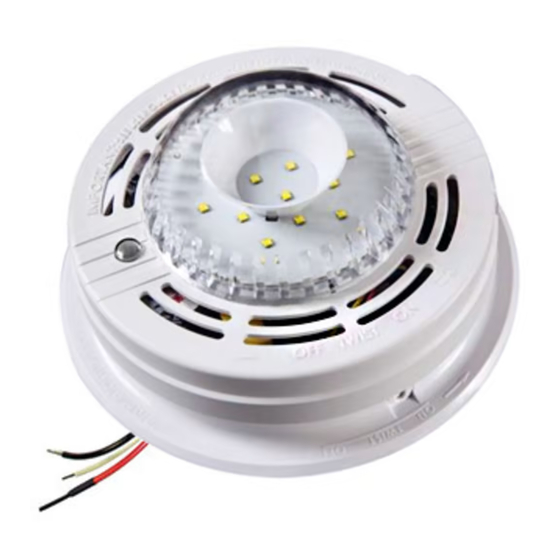
Strobe Light User Guide
ATTENTION! The model SLED177i strobe light is designed to notify hearing impaired
individuals of impending danger. The strobe light has no detection means and MUST be
used in conjunction with operating and interconnected Smoke, Heat, or Carbon
Monoxide Alarms.
The model SLED177i AC wire-in Strobe light can be directly interconnected with Kidde
Safety 3-wire Smoke, Heat and CO alarms. It will produce an intermittent strobe flash
pattern (approximately 4 flashes, followed by approximately 5 seconds off) when trig-
gered by a Carbon Monoxide alarm and a flash every second when triggered by a
smoke or heat alarm.
Thank you for purchasing this strobe light. It is an important part of your family's home
safety plan. You can trust KIDDE Safety to provide the highest quality safety products.
We know you expect nothing less when the lives of your family are at stake.
For your convenience, write down the following information. If you call
our Consumer Hotline, these are the first questions you will be asked.
Strobe Light Model Number
(located on back of alarm):
Date Code (located on back of device):
Date of Purchase:
Where Purchased:
For model: SLED177i
SLED177i
1102-7201-00
Advertisement
Table of Contents

Related Manuals for Kidde SLED177i


Summary of Contents for Kidde SLED177i
- Page 1 Smoke, Heat, or Carbon Monoxide Alarms. The model SLED177i AC wire-in Strobe light can be directly interconnected with Kidde Safety 3-wire Smoke, Heat and CO alarms. It will produce an intermittent strobe flash...
- Page 2 IMPORTANT! READ ALL INSTRUCTIONS BEFORE INSTALLATION AND SAVE THIS USER GUIDE FOR FUTURE REFERENCE WARNING! THIS VISUAL SIGNALING DEVICE HAS NO DETECTION MEANS. IT MUST BE USED IN CONJUNCTION WITH OPERATING AND INTERCONNECTED ALARMS. WARNING! DO NOT TRY TO REPAIR THIS STROBE LIGHT YOURSELF REFER TO THE INSTRUCTIONS IN SECTION 11 FOR SERVICE.
-
Page 3: Specifications
SLED177i ( 3 WIRE INTERCONNECT UNIT ) Electrical Rating: Regulated 120VAC (96-132VAC) Maximum Operating RMS Current 630 mA Multiple station (24) interconnect unit, interfaces directly with Kidde Safety: Ion Smoke Alarm Models: 1235, 1275, 1276, 1285, i12020, i12020A i12040, i12040A, i12060,i2060A, i4618,... -
Page 4: Locations To Avoid
The following diagram shows that the light intensity gradually decreases as the viewing angle is increased. Use this information to determine the best location for the strobe light. 2. APPLICATIONS LIGHT LIGHT 90° 90° SOURCE SOURCE CEILING CEILING PERCENT PERCENT ANGLE ANGLE 90°... -
Page 5: Installation Instructions
1. When Strobe lights and alarms are interconnected, all the interconnected devices must be powered from the same circuit. 2. A maximum of 24 Kidde Safety devices may be interconnected in a multiple station arrangement. The interconnect system should not exceed the NFPA interconnect limits of 12 smoke alarms and/or 18 alarms total (smoke, heat, Carbon Monoxide, etc). - Page 6 4. The maximum wire run distance between the first and last device in an inter- connect system is 1000 ft. 5. Figure 1 illustrates interconnection wiring. Improper connection will result in damage to the strobe light or alarms, failure to operate, or a shock hazard. 6.
-
Page 7: Mounting Instructions
MOUNTING INSTRUCTIONS: • A mounting plate is provided on the back of the strobe light. This mounting plate is installed on the electrical box between the electrical box and the strobe light. • Remove the mounting plate from the back of the strobe light by holding the mounting plate and twisting the strobe light in the direction indicated by the "OFF"... - Page 8 (See fig. 4) • Turn on the AC power. The model SLED177i strobe light has a green AC power on indicator which should be lit when the strobe is correctly powered.
-
Page 9: Testing And Operation
CAUTION! Early warning fire detection and visual notification is best achieved by the installation of fire detection and visual notification equipment in all rooms and areas of the household as follows: A smoke alarm and visual notification device installed and interconnected in each separate sleeping area, and visual notification equipment interconnected with heat, smoke, or CO alarms in the living rooms, dining rooms, kitchens, hallways, attics, furnace rooms, closets, utility storage rooms, basements, and attached garages. - Page 10 PIN” IN SECTION (5) FOR PIN REMOVAL INSTRUCTIONS. CLEANING YOUR STROBE LIGHT: To clean your Strobe light remove it from the mounting plate and disconnect the AC Quick Connect power harness as outlined in section 5. You can clean dust from your strobe light by using a vacuum cleaner hose and vacuuming around the cover and lens openings on the strobe light.
-
Page 11: Good Safety Habits
BEDROOM OR ON A DIFFERENT FLOOR, IT WILL NOT WAKE UP A SOUND SLEEPER. THE USE OF ALCOHOL OR DRUGS MAY ALSO IMPAIR ONE’S ABILITYTO RESPOND TO THE VISUAL SIGNAL. ALTHOUGH VISUAL SIGNALING DEVICES CAN HELP SAVE LIVES BY PROVIDING AN EARLY WARNING OF AN EMERGENCY SITUATION, THEY ARE NOT A SUBSTI- TUTE FOR AN INSURANCE POLICY. -
Page 12: Nfpa Required Protection
WHAT TO DO WHEN THE ALARM ACTIVATES • Alert small children in the home. • Leave immediately by your escape plan. Every second counts, so don’t waste time getting dressed or picking up valuables. • In leaving, don’t open any inside door without first feeling its surface. If hot, or if you see smoke seeping through cracks, don’t open that door! Instead, use your alternate exit. -
Page 13: Service And Warranty
If after reviewing this user guide you feel that your Visual Signaling Device is defective in any way, do not tamper with the unit. Return it for servicing to: KIDDE SAFETY, 1016 Corporate Park Dr., Mebane, NC. 27302 (See Warranty for in-warranty returns). -
Page 14: Ten Year Limited Warranty
The obligation of KIDDE Safety under this warranty is limited to repairing or replacing the Visual Signaling Device...