Table of Contents
Advertisement
Quick Links
Copyright and Warranty Notice
The information in this document is subject to change without notice and does not
represent a commitment on part of the vendor, who assumes no liability or
responsibility for any errors that may appear in this manual.
No warranty or representation, either expressed or implied, is made with respect to
the quality, accuracy or fitness for any particular part of this document. In no event
shall the manufacturer be liable for direct, indirect, special, incidental or
consequential damages arising from any defect or error in this manual or product.
Product names appearing in this manual are for identification purpose only and
trademarks and product names or brand names appearing in this document are
property of their respective owners.
This document contains materials protected under International Copyright Laws. All
rights reserved. No part of this manual may be reproduced, transmitted or
transcribed without the expressed written permission of the manufacturer and
authors of this manual.
If you do not properly set the motherboard settings causing the motherboard to
malfunction or fail, we cannot guarantee any responsibility.
Advertisement
Table of Contents

Related Manuals for Abit AB-CX6


Summary of Contents for Abit AB-CX6
- Page 1 Copyright and Warranty Notice The information in this document is subject to change without notice and does not represent a commitment on part of the vendor, who assumes no liability or responsibility for any errors that may appear in this manual. No warranty or representation, either expressed or implied, is made with respect to the quality, accuracy or fitness for any particular part of this document.
-
Page 3: Table Of Contents
CX6 Motherboard User’s Manual Table of Contents Chapter 1. Introduction of CX6 Features 1-1. Features of this Motherboard 1-2. Specifications 1-3. Layout Diagram 1-4. The System Block Diagram 1-10 Chapter 2. Installing the Motherboard 2-1. Installing the Motherboard to the Chassis ... - Page 4 ® Appendix A Intel INF Installation Utility for Windows 98 SE ® Appendix B Installing the Audio Driver for Windows 98 SE ® Appendix C Installing the Audio Drivers for the Windows Appendix D BIOS Flashing User Instructions Appendix E Installing the HighPoint XStore Pro Utility Appendix F Hardware Monitoring Function (Installing the...
-
Page 5: Chapter 1. Introduction Of Cx6 Features
Introduction of CX6 Features Chapter 1. Introduction of CX6 Features 1-1.Features of this Motherboard This motherboard is designed for the new generation of CPUs. It supports the Intel SLOT1 structure (Pentium II/III processor), up to 1GB of memory, super I/O, and Green PC functions. - Page 6 Chapter1 Supports the Katmai and Coppermine processors at 100/133MHz for Slot 1 Supports an IOQ (In-Order Queue) depth of 6 GTL+ host bus supporting 32-bit host addressing Single Direct Rambus channel optimized for 300, 356 and 400 MHz operation 1GB DRAM supported with 256Mbit memory technology AGP 2.0 interface with 1x/2x/4x data transfer and 2x/4x fast write capability The hub interface (link) to ICH Fully optimized data paths and buffering...
- Page 7 Introduction of CX6 Features scalable Original Equipment Manufacturer (OEM) motherboard riser board and interface, which supports both audio and modem functions. The specification's main objective is to reduce the baseline implementation cost of audio and modem functionality. In accordance with PC user's demands for feature-rich PCs, combined with the industry's current trend towards lower cost PCs, all of theses functions are built into the motherboard.
- Page 8 Chapter1 DRAM synchronization has set the stage for system designers to move from a 66MHz to a 100 MHz system bus, partially closing the speed gap between processor and memory. But even as engineering teams wrestle with this design challenge, microprocessors are advancing to speeds of 300MHz, 400MHz, and beyond.
- Page 9 Introduction of CX6 Features Ultra DMA/66 The CX6 supports Ultra ATA/66 IDE devices. Ultra ATA/66 is the new standard for IDE devices. It enhances existing Ultra ATA/33 technology by increasing both performance and data integrity. This new high-speed interface doubles the Ultra ATA/33 burst data transfer rate to 66.6 Mbytes/sec.
-
Page 10: Specifications
Chapter1 1-2. Specifications 1. CPU ® # Supports Intel Pentium III Coppermine with 128/256K ® # Supports Intel Pentium III Katmai # Supports Intel Pentium III 450 ~ 800 MHz Processor cartridge. # Supports Intel Pentium II 350 ~ 450 MHz Processor cartridge. - Page 11 Introduction of CX6 Features # Programmable Power Down Mode # Supports EAPD (External Amplifier Power Down) # Power Supplies: Analog 5.0V, Digital 3.3V 5. System BIOS ™ # CPU SOFT MENU II, can easily set the processor parameters # AWARD BIOS # Supports Plug-and-Play (PnP) # Supports Advanced Configuration Power Interface (ACPI) # Supports Desktop Management Interface (DMI)
- Page 12 Chapter1 $ $ $ $ Supports Wake On LAN, Keyboard or Mouse, but your ATX power supply 5V standby power must be able to provide at least a 720mA current capacity. Otherwise, you may fail to boot up the system % Specifications and information contained in this manual are subject to change without notice.
-
Page 13: Layout Diagram
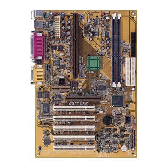
Introduction of CX6 Features 1-3. Layout Diagram Figure 1-1. Motherboard component location User’s Manual... -
Page 14: The System Block Diagram
1-10 Chapter1 1-4. The System Block Diagram Figure 1-2. System diagram of the Intel 820 chipset... -
Page 15: Chapter 2. Installing The Motherboard
Installing the Motherboard Chapter 2. Installing the Motherboard This CX6 motherboard not only provides all standard equipment for classic personal computers, but also provides great flexibility for meeting future upgrade demands. This chapter will introduce step by step all the standard equipment and will also present, as completely as possible, future upgrade capabilities. -
Page 16: Installing The Motherboard To The Chassis
Chapter2 2-1. Installing the Motherboard to the Chassis Most computer chassis will have a base on which there will be many mounting holes that allows the motherboard to be securely attached and at the same time, prevents short circuits. There are two ways to attach the motherboard to the base of chassis: # with studs # or with spacers Please refer to the figure 2-1 that shows the studs and spacers, they may have several types,... -
Page 17: Installation Of The Pentium Ii/Iii Cpu
Installing the Motherboard Note If the motherboard has mounting holes, but they don’t line up with the holes on the base and there are no slots to attach the spacers, don’t worry, you can still attach the spacers to the mounting holes. Just cut the bottom portion of spacers (the spacer may be a little hard to cut off, so be careful of your hands). -
Page 18: Installing System Memory
Chapter2 2-3. Installing System Memory The memory module for the Camino chipset is different from conventional DIMM. It is called RIMM (Rambus In-line Memory Module). The RIMM conforms to the standard DIMM form factor, but it is not pin-compatible. Its architecture is based on the electrical requirements of the DRC (Direct Rambus Channel) high-speed bus operating at a clock rate of 400MHz which enables a data rate of 800MHz because data is clocked on both clock edges. - Page 19 Installing the Motherboard Unlike installing SIMMs, RIMMs may be "snapped" directly into the socket. Note: Certain RIMM sockets have minor physical differences. If your module doesn't seem to fit, please Fig. 2-3 Direct RDRAM module do not force it into the socket as you may damage your memory module or RIMM socket.
- Page 20 Chapter2 Note When you install a RIMM module fully into the RIMM socket, the eject tab should be locked into the RIMM module very firmly and fit into its indention on the both sides.
-
Page 21: Connectors, Headers And Switches
Installing the Motherboard 2-4. Connectors, Headers and Switches Inside the case of any computer several cables and plugs have to be connected. These cables and plugs are usually connected one-by-one to connectors located on the motherboard. You need to carefully pay attention to any connection orientation the cables may have and, if any, notice the position of the first pin of the connector. - Page 22 Chapter2 ATX: ATX Power Input Connector Caution If the power supply connectors are not properly attached to the ATX power supply, the power supply or add-on cards may be damaged. Attach the connector from the power supply to the ATX connector here. Remember you have to push the connector from the ATX power supply firmly to the end with the ATX connector, insuring that you have a...
- Page 23 Installing the Motherboard IRCIR1: IR Header (Infrared) There is a specific orientation for pins 1 through 5, attach the connector from the IR KIT or IR device to the IRCIR1 header. This motherboard supports standard IR transfer rates. Note: Watch the pin position and the orientation WOM1: Wake On Modem Header If you have an internal modem adapter that...
- Page 24 2-10 Chapter2 SMB: System Management Bus Connector This connector is reserved for system management bus (SMBus). The SMBus is a specific implementation of an I C bus. I C is a multi-master bus, which means that multiple chips can be connected to the same bus and each one can act as a master by initiating a data transfer.
- Page 25 Installing the Motherboard 2-11 JP2 Jpmper This jumper is reserved for boot failure. JP5 Jumper This jumper lets you select the CODEC mode on the AMR card. When pin 1 and pin 2 jumpers are shorted (default), the CODEC on the AMR card is set to secondary mode. If pin 2 and pin 3 jumpers are shorted, the onboard audio CODEC is disabled and CODEC on the AMR card is set to primary...
- Page 26 2-12 Chapter2 LED1: Standby LED This LED is called the Stand-By LED. It shows if the motherboard is in the power on state, or is fully powered down. If this LED light is on, that means your motherboard is not fully powered down. You can't disassemble any components, add-on cards, CPU, or RAM modules in this state.
- Page 27 Installing the Motherboard 2-13 Normal Operation (Default) Discharge CMOS Figure 2-7. CCMOS1 jumper setting Note Before you clear the CMOS, you have to turn the power off first (including the +5V standby power). Otherwise, your system may work abnormally or malfunction. PN1 and PN2 Headers PN1 and PN2 are for switches and indicators for the chassis’s front panel, there are...
- Page 28 2-14 Chapter2 PN1 (Pin 6-7): HDD LED Header Attach the cable from the case’s front panel HDD LED to this header. If you install it in the wrong direction, the LED light will not illuminate correctly. Note: Watch the HDD LED pin position and the orientation. PN1 (Pin 8-9): Power on Switch Header Attach the cable from the case’s front panel power switch to this header.
- Page 29 Installing the Motherboard 2-15 PN2 (Pin 9-10): Suspend LED Header Insert the two-threaded suspend LED cable into pin 9 and pin 10. If you install it in the wrong direction, the LED light will not illuminate correctly. Note: Watch the HDD LED pin position and the orientation. For the PN1 and PN2 pin’s count-name list, please refer to table 2-2.
- Page 30 2-16 Chapter2 connection of two floppy disk drives. After connecting the single end to the FDC1, connect the two connectors on the other end to the floppy disk drives. In general, people only install one floppy disk drive on their computer system. Note A red mark on a wire typically designates the location of pin 1.
- Page 31 Installing the Motherboard 2-17 Note #The Master or Slave status of the hard disk drive is set on the hard disk itself. Please refer to the hard disk drive user’s manual. #A red mark on a wire typically designates the location of pin 1. You need to align the wire pin 1 to the IDE connector pin 1, then insert the wire connector into the IDE connector.
- Page 32 2-18 Chapter2 Ultra ATA/66 protocol and commands are designed to be compatible with existing ATA (IDE) devices and systems. Although a new 40-pin, 80-conductor cable is required for Ultra ATA/66, the chip set pin connector remains the same at 40. Hard drives that support Ultra ATA/66 also support Ultra ATA/33 and legacy ATA (IDE) specifications.
- Page 33 Installing the Motherboard 2-19 Figure 2-12. CX6 back panel connectors Figure 2-12 shows the CX6 back panel connectors, these connectors are for connection to outside devices to the motherboard. We will describe which devices will attach to these connectors below. KM1 Lower: PS/2 Keyboard Connector Attach a PS/2 keyboard connector to this 6- pin Din-connector.
- Page 34 2-20 Chapter2 Serial Port COM1 and COM2 Connector This motherboard provides two COM ports, you can connect an external modem, mouse other devices that support this communication protocol. Parallel Port Connector This parallel port is also called an “LPT” port, because it usually connects to the printer.
-
Page 35: Chapter 3. Introduction Of The Bios
Introduction of the BIOS Chapter 3. Introduction of The BIOS The BIOS is a program located on a FWH (Firmware Hub) chip on the motherboard. This program will not be lost when you turn the computer off. This program is also referred to as the “boot”... - Page 36 Chapter3 Note * To improve stability and functions, BIOSes are constantly improving, therefore; the BIOS screens in this chapter may not fully match your current BIOS screen. + All default setting is use the Load Optimized Defaults settings. If you use the Load Fail-Safe Defaults, some items default values will be changed.
- Page 37 Introduction of the BIOS # Press F5 to reset current screen settings to their Setup Default values. # Press F6 to return to the Fail-Safe Default setting i.e. if you use the wrong settings causing a system boot failure, use this function key to quickly return to the system default settings.
-
Page 38: Cpu Soft Menu
Chapter3 3-1. CPU Soft Menu™ II The CPU can be setup through a programmable switch (CPU SOFT MENU ™ II), that replaces the traditional manual hardware configuration. This feature allows the user to more easily complete the installation procedures. You can install the CPU without configuring any jumpers or switches. - Page 39 Introduction of the BIOS User defined external clock and multiplier factor: User Defined: When you choose the User Define, you will bw able to set the following five items. &&&& &&&& &&&& &&&& &&&& &&&& &&&& &&&& Warning The wrong settings of the multiplier and external clock in certain circumstances may cause CPU damage.
- Page 40 Chapter3 have to be aware that if you set the L2 cache speed too fast, it will cause the L2 cache to fail. If the L2 cache fails it will cease to run until you reset the value, but the processor and L1 cache will still function, just not as well.
- Page 41 Introduction of the BIOS Attention After setting up the parameters and leaving the BIOS SETUP, and having verified that the system can be booted, do not press the Reset button or turn off the power supply. Otherwise the BIOS will not read correctly, the parameters will fail and you must enter ™...
-
Page 42: Standard Cmos Features Setup Menu
Chapter3 3-2. Standard CMOS Features Setup Menu This contains the basic configuration parameters of the BIOS. These parameters include date, hour, VGA card, FDD and HDD settings. Figure 3-3. Standard CMOS Setup Screen Shot Date (mm:dd:yy): You can set the date in this item: month (mm), date (dd) and year (yy). Time (hh:mm:ss): You can set the time in this item: hour (hh), minute (mm) and second (ss). - Page 43 Introduction of the BIOS Figure 3-4. IDE Primary Master Setup Screen Shot IDE HDD Auto-Detection: Press the Enter key for the BIOS to auto detect all detailed parameters of the hard disk drivers (HDD). If auto detection is successful, the correct values will be shown in the remaining items of this menu.
- Page 44 3-10 Chapter3 Access Mode: Since old operating systems were only able to support HDDs with capacities no bigger than 528MB, any hard disk with more than 528MB was unusable. AWARD BIOS features a solution to this problem: you can, according to your operating system, choose four operating modes: NORMAL .
- Page 45 Introduction of the BIOS 3-11 Note All the items below are available when you set the item Primary IDE Master to Manual. Cylinder: When disks are placed directly above one another along the shaft, the circular vertical "slice" consisting of all the tracks located in a particular position is called a cylinder. You can set the number of cylinders for a HDD.
- Page 46 3-12 Chapter3 Floppy 3 Mode Support: Four options are available: Disabled . Driver A . Driver B . Both. The default setting is Disabled. 3 Mode floppy disk drives (FDD) are 3 1/2” drives used in Japanese computer systems. If you need to access data stored in this kind of floppy, you must select this mode, and of course you must have a 3 Mode floppy drive.
-
Page 47: Advanced Bios Features Setup Menu
Introduction of the BIOS 3-13 3-3. Advanced BIOS Features Setup Menu In each item, you can press <Enter> at any time to display all the options for this item. Attention Advanced BIOS Features Setup Menu has already been set for maximum operation. If you do not really understand each of the options in this menu, we recommend you use the default values. - Page 48 3-14 Chapter3 feature. The default setting is Enabled. CPU Level 2 Cache: This item is used to enable or to disable the CPU level 2 cache. When the external cache is enable, it will speed up memory access, and the system works faster. The default setting is Enabled.
- Page 49 Introduction of the BIOS 3-15 Boot Other Device: Two options are available: Enabled or Disabled. The default setting is Enabled. This setting allows the BIOS to try three kinds of boot devices that set from the above three items. Swap Floppy Drive: This item can be set as Enabled or Disabled.
- Page 50 3-16 Chapter3 . 15 . 20 . 24 . 30 . Back to 6. The default setting is 30. Typematic Delay (Msec): When you press a key continuously, if you exceed the delay you have set here, the keyboard will automatically repeat the keystroke according to a certain rate (Unit: milliseconds). Four options are available: 250 .
- Page 51 Introduction of the BIOS 3-17 Report No FDD For WIN 95: ® When using Windows 95 without a floppy drive, please set this item to Yes. Otherwise, set it to No. The default setting is No. Delay IDE Initial (Sec): This item is used to support some old models or special types of hard disks or CD-ROMs.
-
Page 52: Advanced Chipset Features Setup Menu
3-18 Chapter3 3-4. Advanced Chipset Features Setup Menu The Advanced Chipset Features Setup Menu is used to modify the contents of the buffers in the chipset on the motherboard. Since the parameters of the buffers are closely related to hardware, if the setup is not correct or is false, the motherboard will become unstable or you will not be able to boot up. - Page 53 Introduction of the BIOS 3-19 When you set the CPU external frequency to 133MHz, you can only choose 356MHz or 400Mhz. SDRAM CAS Latency Time: Three options are available: 2, 3 and Auto. The default setting is Auto. You can select SDRAM CAS (Column Address Strobe) latency time according your SDRAM specification.
- Page 54 3-20 Chapter3 Memory Hole At 15M-16M: Two options are available: Enabled and Disabled. The default setting is Disabled. This option is used to reserve the memory block 15M-16M for ISA adapter ROM. Some special peripherals need to use a memory block located between 15M and 16M, and this memory block has a size of 1M.
-
Page 55: Integrated Peripherals
Introduction of the BIOS 3-21 3-5. Integrated Peripherals In this menu, you can change the onboard I/O device and other hardware peripheral settings. Figure 3-7. Integrated Peripherals Onboard IDE-1 Controller: The onboard IDE 1 controller can be set as Enabled or Disabled. The default setting is Enabled. - Page 56 3-22 Chapter3 (0-4) for each of the four IDE devices that the onboard IDE interface supports. Modes 0 through 4 provide successively increased performance. In Auto mode (default setting), the system automatically determines the best mode for each device. Master/Slave Drive Ultra DMA: Two options are available: Auto and Disabled.
- Page 57 Introduction of the BIOS 3-23 AC97 Audio: Two options are available: Auto and Disabled. The default setting is Auto. If you set it to Enabled, it will allow the BIOS to detect audio device you use. If an audio device is detected, the onboard audio controller (810 chipset family) will be able to support it.
- Page 58 3-24 Chapter3 Keyboard 98: ® If you are using Windows 98 and you have a keyboard that is designed for the ® Windows 98 operating system. You can enable this item, and use your keyboard wake up key to wake up your computer. Hot Key Power On: There are twelve options are available, Ctrl-F1 to Ctrl-F12.
- Page 59 Introduction of the BIOS 3-25 Duplex Mode Select: Two options are available: Full and Half. The default setting is Full. This item is lets you choose the operation mode for your IR KIT. Some IR device only can work at half duplex mode.
- Page 60 3-26 Chapter3 Midi Port Address: Three options are available: Disabled . 330 . 300 . 290. The default setting is 330. This item sets the address of the onboard midi port connector. Midi Port IRQ: Two options are available: 5 . 10. The default setting is 10. This item sets the IRQ of the onboard midi port connector.
-
Page 61: Power Management Setup Menu
Introduction of the BIOS 3-27 3-6. Power Management Setup Menu The difference between Green PCs and traditional computers is that Green PCs have a power management feature. With this feature, when the computer is powered on but inactive, the power consumption is reduced in order to save energy. When the computer operates normally, it is in Normal mode. - Page 62 3-28 Chapter3 2. Use the arrow keys to go to the item you want to configure. To change the settings, use ,,- and Enter key. 3. After you have configured the power management feature, press Esc to go back to the Main Menu.
- Page 63 Introduction of the BIOS 3-29 System States and Power States Under ACPI, the operating system directs all system and device power state transitions. The operating system puts devices in and out of low-power states based on user preferences and knowledge of how devices are being used by applications. Devices that are not being used can be turned off.
- Page 64 3-30 Chapter3 # Dynamic RAM context is maintained. # Power Resources are in a state compatible with the system S1 state. All Power Resources that supply a System Level reference of S0 are in the OFF state. # Devices states are compatible with the current Power Resource states. Only devices which solely reference Power Resources which are in the ON state for a given device state can be in that device state.
- Page 65 Introduction of the BIOS 3-31 Power Management: This item allows you to select the type (or degree) of power saving and is directly related to the following modes: 1. Suspend Mode 2. HDD Power Down There are three options for power management, three of which have fixed mode settings: User Define “User Define”...
- Page 66 3-32 Chapter3 V/H SYNC + Blank: This selection will cause the system to turn off the vertical and horizontal synchronization ports and write blanks to the video buffer. Initial display power management signaling. DPMS: Video Off In Suspend: Two options are available: Yes or No. The default setting is Yes. This item determines the manner in which the monitor is blanked.
- Page 67 Introduction of the BIOS 3-33 Soft-Off by PWR-BTTN: Two options are available: Instant-Off and Delay 4 Sec.. The default setting is Instant-Off. Pressing the power button for more than four seconds forces the system to enter the Soft-Off state when the system has "hung". Wake-Up by PCI card: Two options are available: Enabled and Disabled.
- Page 68 3-34 Chapter3 time counting. Primary IDE 0 / Primary IDE 1: Two options are available: Enabled and Disabled. The default setting is Disabled. If any primary IDE master/slave I/O activity occurs, it will cause the computer to re-count the time elapsed. Secondary IDE 0 / Secondary 1: Two options are available: Enabled and Disabled.
-
Page 69: Pnp/Pci Configurations
Introduction of the BIOS 3-35 3-7. PnP/PCI Configurations This section describes configuring the PCI bus system. PCI, or Personal Computer Interconnect, is a system which allows I/O devices to operate at speeds nearing the speed the CPU itself uses when communicating with its own special components. This section covers some very technical items and it is strongly recommended that only experienced users should make any changes to the default settings. - Page 70 3-36 Chapter3 Resources Controlled By: Two options are available: Auto(ESCD) and Manual. Default setting is Auto(ESCD). When the setting is Auto(ESCD), the IRQ Resources can not be changed. When resources are controlled manually, the IRQ Resources can then be changed. The Award Plug and Play BIOS has the capability to automatically configure all of the boot and PnP compatible devices.
- Page 71 Introduction of the BIOS 3-37 PIRQ_0~PIRQ3: Eleven options are available: Auto, 3, 4, 5, 7, 9, 10, 11, 12, 14, 15. Default setting is Auto. This item allows the system to automatically specify the IRQ number for the device installed on PCI slots.
-
Page 72: Pc Health Status
3-38 Chapter3 3-8. PC Health Status You can set the warning and shutdown temperatures for your computer system, and you can check the fan speeds and power supply voltages of your computer system. The features are useful for monitoring all the important parameters within your computer system. We call it the PC Health Status. - Page 73 Introduction of the BIOS 3-39 The following items list the voltage states of the system power. It is also unchangeable. Note The hardware monitoring features for temperatures, fans and voltages will occupy the I/O address from 294H to 297H. If you have a network adapter, sound card or other add-on cards that might use those I/O addresses, please adjust your add-on card I/O address, to avoid the use of those addresses.
-
Page 74: Load Fail-Safe Defaults
3-40 Chapter3 3-9. Load Fail-Safe Defaults Figure 3-12. Load Fail-Safe Defaults Screen Shot When you press <Enter> on this item you get a confirmation dialog box with a message similar to: Load Fail-Safe Defaults (Y/N) ? N Pressing ‘Y’ loads the BIOS default values for the most stable, minimal-performance system operations. -
Page 75: Set Password
Introduction of the BIOS 3-41 When you press <Enter> on this item you get a confirmation dialog box with a message similar to: Load Optimized Defaults (Y/N) ? N Pressing ‘Y’ loads the default values that are factory settings for optimal performance system operations. -
Page 76: Save & Exit Setup
3-42 Chapter3 3-12. Save & Exit Setup Figure 3-14. Save & Exit Setup Screen Shot Pressing <Enter> on this item asks for confirmation: Save to CMOS and EXIT (Y/N)? Y Pressing “Y” stores the selections made in the menus in CMOS - a special section of memory that stays on after you turn your system off. -
Page 77: Exit Without Saving
Introduction of the BIOS 3-43 3-13. Exit Without Saving Figure 3-15. Exit Without Saving Screen Shot Pressing <Enter> on this item asks for confirmation: Quit without saving (Y/N)? Y This allows you to exit Setup without storing in CMOS any change. The previous selections remain in effect. - Page 78 3-44 Chapter3...
- Page 79 Please insert the CX6 CD-Title into your CD-ROM drive. It should execute the program automatically. If not, you can go to the CD location and execute the execution file (Abit.exe) from the main directory of this CD-Title. After it is executed, please choose “Drivers .
- Page 80 Appendix A This screen will show you the Readme.txt information of this INF installation utility. When you have read it all, click "Next". When installation is complete, the installer will ask you to restart your computer. We suggestion you click "Yes" to restart your computer to finish the system INF updating.
- Page 81 ® Installing the Audio Driver for Windows 98 SE Appendix B Installing the Audio Driver for ® Windows 98 SE ® We will show you how to install the audio drivers for Windows 98 SE operating system. Please enter Control Panel, then check System Properties .
- Page 82 Appendix B Select “Search for a better driver than the your device using now. (Recommended)”, and then click “Next.” Select “Specify a Location” and then type “D:\Drivers\YMF752\WIN9X” in the text box. (D is your CD-ROM drive letter) Click “Next.” Click “Next.” Click “Finish.”...
- Page 83 ® Installing the Audio Driver for Windows 98 SE Once Windows has restarted, go to "System Properties" to double check. You should find the "?PCI Multimedia Audio Device" has disappeared, and Yamaha AC-XG audio Codec is there instead. User’s Manual...
- Page 84 Appendix B...
- Page 85 ® Installing the Audio Drivers for the Windows Appendix C Installing the Audio Drivers for ® the Windows ® In this section we will show you how to install the audio drives to your Windows NT 4.0 ® Server/Workstation operating system. All screen shot are from Windows NT 4.0 Workstation version.
- Page 86 Appendix C You have to specify and manually type the path of driver location. We’ve put the audio drivers under the "DRIVERS\YMF752\ NT4.0". The code name of the CD-ROM drive will depend on how many devices installed on your computer system. Here it is shown as D:\.
- Page 87 BIOS Flashing User Instructions Appendix D BIOS Flashing User Instructions When your motherboard needs to be upgraded with new features or some compatibility problems in the BIOS need to be fixed, you will need to use this BIOS flash utility. This utility is provided by Award Software makes it easy to flash by yourself.
- Page 88 Appendix D Figure D-2. Award Flash Memory Writer V7.52C Complete Screen Figure D-3 shows you what commands you can use for the flashing program. You need to go into the pure DOS environment and type awdflash. Figure D-3 will then appear. Figure D-3.
- Page 89 For example, if you want to update the CX6 BIOS, please follow the procedures described below. Step 1. Please visit our website (www.abit.com.tw) and download the following files: ABITFAE.BAT, AWDFLASH.EXE and the CX6’s newest BIOS file-- CX6_QG.EXE for example. After you download these three files, please execute the “CX6_QG.EXE.”...
- Page 90 Appendix D...
- Page 91 Installing HighPoint XStore Pro Utility Appendix E Installing the HighPoint XStore Pro Utility We provide a useful and powerful utility on our product package, HighPoint XStore Pro. What does XStore do? The XStore Pro is a hard disk enhancement utility which improves system performance.
- Page 92 Appendix E ® 2. This Windows 95/98 driver does not support CD-ROM Changers. If you have an ATAPI CD-ROM Changer installed in your system, please do not install this driver! ® ® 3. We have found that the Windows 95 OSR2/Windows 98 version fails to load the driver on some systems using the Bus Master chipset after you install and restart the system.
- Page 93 Installing HighPoint XStore Pro Utility have a floppy diskette instead of the CD-ROM, just insert the diskette and run the Setup.exe file to start installation. ® Step 1: In Windows 95/98, place the CD-ROM into the computer. The main menu will show up.
- Page 94 Appendix E Step 3: Press the “Next” key, You will see the license screen. Step 4: Press “Yes” to continue. Step 5: When the installation process is done, you will see the screen below. This screen will show up only when you install both XStore Pro and CD Xpress.
- Page 95 Installing HighPoint XStore Pro Utility Step 6: Choose the “Yes, I want to restart my computer now.” Button. Then system will restart. Or you can choose the “No, I will restart my computer later”. Note You must restart your computer after installing the XStore Pro utility. Otherwise, the software may not work properly.
- Page 96 Appendix E...
- Page 97 Hardware Monitoring Function Appendix F Hardware Monitoring Function (Installing the Winbond Hardware Doctor Utility) Winbond Hardware Doctor is a self-diagnostic system for PCs and must be used with the Winbond chipset: W83627HF IC series products. It protects PC hardware by monitoring several critical items including power supply voltages, CPU &...
- Page 98 Appendix F Step 3. You can specify the program install path by clicking the “Change Directory” button. Or if you want to use the default path, click the icon to continue the install process. Now the screen will show you the percentage of installation progress.
- Page 99 Hardware Monitoring Function Step 6. This screen will appear. You will see voltages, fan speeds and temperature readings as well. If any item readings are critical or over their limitations, the reading will turn red. Also, a pop-up window will appear to warn you the system has a problem! The figure below shows the warning message window.
- Page 100 Appendix F Please pay attention to two things when you want to make any changes to the “Configuration” option. Firstly, you have to make sure your new setting is in the proper range. Secondly, after you finished the configuration, you have to save it. Otherwise, the program will start with the default value the next time.
- Page 101 The Installation Guide for Suspend to RAM Appendix G Installation Guide for Suspend to Suspend To RAM (STR) is a cost-effective, optimal implementation of the ACPI 1.0 specification. The ACPI specification defines the S3 sleep state, in which all system context is lost except system memory.
- Page 102 Appendix G After these items show up, you can go to the next step for the STR function setting. 0 How to use the STR function: There are two ways to put your system into STR mode: Method 1: Select “Stand by” in the “Shut Down Windows” area. Step 1: Click “Star”...
- Page 103 The Installation Guide for Suspend to RAM Method 2: Define the case “Power” button to initiate STR sleep Mode Step 1: Open “Control Panel”, and then enter “Power Management”. Step 2: Select “Advanced”, and then set the “Power Buttons” to “Standby”. Step 3: Restart your computer to put these settings into effect.
- Page 104 Appendix G...
- Page 105 Fax this form to your dealer or to the company where you bought the hardware or your nearest ABIT branch office in order to benefit from our technical support. (You can refer to the examples given below) Example 1: With a system including: motherboard (with CPU, DRAM, COAST...) HDD,...
- Page 106 Appendix H line that loads the Sound Card Driver, add a remark REM, in order to disable the Sound Card Driver. See the example below. CONFIG.SYS: DEVICE=C:\DOS\HIMEM.SYS DEVICE=C:\DOS\EMM386.EXE HIGHSCAN DOS=HIGH, UMB FILES=40 BUFFERS=36 REM DEVICEHIGH=C:\PLUGPLAY\DWCFGMG.SYS LASTDRIVE=Z Restart the system. If the system starts and does not reset, you can be sure that the problem is due to the Sound Card Driver.
- Page 107 Troubleshooting (Need Assistance?) 4. DRIVER REV: Note the driver version number indicated on the DEVICE DRIVER disk (if have) as “Release *.**”. For example: User’s Manual...
- Page 108 Appendix H . OS/APPLICATION: Indicate the operating system and applications your are running on the system. ® ® ® Example: MS-DOS 6.22, Windows 95, Windows NT..CPU: Indicate the brand and the speed (MHz) of your CPU. Example:(A) In the “Brand” space, write “Intel”, in the “Specifications” space, write ®...
-
Page 109: Rev
Troubleshooting (Need Assistance?) ' Technical Support Form Company name: 8 Phone #: 3 Contact: 9Fax #: Model BIOS ID # Motherboard DRIVER REV Model No. OS/Application Hardware name Brand Specifications IDE1 IDE2 IDE1 IDE2 Drive System Memory (DRAM) ADD-ON CARD Problem Description: User’s Manual... - Page 110 Appendix H...
- Page 111 (In Europe) http://www.abit.nl Thank you for choosing ABIT products. ABIT sells all our products through distributors, resellers and system integrators, we have no direct sales to end-users. Before sending email for tech support please check with your resellers or integrators if you need any services, they are the ones who sold you your system and they should know best as to what can be done, how they serve you is a good reference for future purchases.
- Page 112 ABIT products. Many times you will see that your question has already been asked before. This is a public Internet news group and it is reserved for free discussions, Here is a list of some of the more popular ones: alt.comp.periphs.mainboard.abit...
- Page 113 Stevenage, Herts SG1 2UG, UK abituksales@compuserve.com abituktech@compuserve.com Tel: 44-1438-741 999 Fax: 44-1438-742 899 In Germany and Benelux (Belgium, Netherlands, Luxembourg) countries: AMOR Computer B.V. (ABIT's European Office) Van Coehoornstraat 5a, 5916 PH Venlo, The Netherlands sales@abit.nl technical@abit.nl Tel: 31-77-3204428 Fax: 31-77-3204420...
- Page 114 Please contact the reseller from whom you bought the product. You should be able to get RMA service there. Reporting Compatibility Problems to ABIT. Because of tremendous number of email messages we receive every day, we are forced to give greater weight to certain types of messages than to others.