Table of Contents
Advertisement
Quick Links
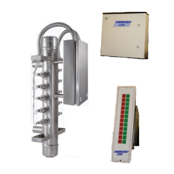
YARWAY 3200 ELECTRONIC WATER LEVEL GAUGE
INSTALLATION, OPERATION AND MAINTENANCE INSTRUCTIONS
Before installation, these instructions must be carefully read and understood.
TABLE OF CONTENTS
Product warranty ................................................ 1
1 Description ................................................ 2
2 Specifications ............................................ 2
3 Available Options ...................................... 2
3.1 Analog 4-20 mA with RS485 Feature ........... 2
4 Packaging and Installation ........................ 3
4.1 Location of the Electronics ........................... 3
4.2 Pressure Vessel ............................................ 3
4.2.1 Freeze Damage Precautions ............... 4
4.3 Probes ............................................................ 4
4.4 Wiring ............................................................. 4
4.4.1 At The Probes ....................................... 4
4.4.2 At The Electronic Module ..................... 4
4.4.3 Protective Ground Wiring ..................... 5
4.4.4 At The Remote Display Panel .............. 5
4.5 Control Outputs ............................................. 5
4.5.1 Detection Outputs ................................. 5
4.5.2 Electronics Fault Output ...................... 5
4.5.3 Level Fault Output ................................ 5
Emerson.com/FinalControl
5 Startup and Operation ............................... 6
5.1 Indicating Lights ............................................ 6
5.2 Pressure Vessel ............................................ 6
5.3 Sensitivity Control ......................................... 6
5.4 Electronic Fault ............................................. 7
5.4.1 Power Supply Fault ................................. 7
5.4.2 Clock Fault ............................................... 7
5.4.3 Optional Continuity (Open Circuit) .......... 7
5.5 Level Error ..................................................... 7
6 Detection Theory ....................................... 7
7 Maintenance .............................................. 8
7.1 Pressure Vessel ............................................ 8
7.2 Probes ............................................................ 8
7.2.1 Probe Removal ........................................ 8
7.2.2 Probe Inspection ..................................... 8
7.2.3 Probe Installation .................................... 8
8 Spare Parts ............................................... 9
TABLE OF FIGURES
Figure # 1 - Vessel Installation ....................... 3
Figure # 2 - Probe HP Assembly......................4
Figure # 3 - Probe Wire Connection ............... 4
Figure # 4 - Ground Symbol ............................ 5
Figure # 5 - Ground Hardware ........................ 5
Figure # 6A - Typical System Wiring Without
Optional Continuity Feature ............................. 10
Figure # 6B - Typical System Wiring With
Optional Continuity Feature ............................. 11
Figure # 7 - Face Plate Label ........................ 12
Figure # 8 - Voltage Jumper Settings .......... 13
Figure # 9 - Remote Display Dimension ...... 14
© 2020 Emerson. All Rights Reserved.
YARWAY PRODUCT WARRANTY
Emerson warrants its Yarway products as
designed and manufactured by Emerson
to be free of defects in the material and
workmanship for a period of one year after
the date of installation or eighteen months
after the date of manufacture whichever is
earliest. Emerson will, at its option, replace
or repair any products which fail during the
warranty period due to defective material or
workmanship.
Prior to submitting any claim for warranty
service, the owner must submit proof of
purchase to Emerson and obtain written
authorization to return the product. Thereafter,
the product shall be returned to Emerson in
Texas, with freight paid.
This warranty shall not apply if the product has
been disassembled, tampered with, repaired or
otherwise altered outside of Emerson factory,
or if it has been subject to misuse, neglect or
accident.
The responsibility of Emerson hereunder is
limited to repairing or replacing the product
at its expense. Emerson shall not be liable
for loss, damage or expenses related directly
or indirectly to the installation or use of
its products, or from any other cause or
for consequential damages. It is expressly
understood that Emerson is not responsible
for damage or injury caused to other products,
buildings, personnel or property, by reason of
the installation or use of its products.
This is Emerson sole warranty and in lieu of all
other warranties, expressed or implied which
are hereby excluded, including in particular all
warranties of merchantability or fitness for a
particular purpose.
This document and the warranty contained
herein may not be modified and no other
warranty, expressed or implied, shall be made
by or on behalf of Emerson unless made in
writing and signed by the General Manager or
Director of Engineering of Emerson.
VCIOM-15704-EN 20/12
Advertisement
Table of Contents

Related Manuals for Emerson YARWAY 3200


Summary of Contents for Emerson YARWAY 3200
-
Page 1: Table Of Contents
4.4 Wiring ............. 4 4.4.1 At The Probes ........4 This is Emerson sole warranty and in lieu of all 4.4.2 At The Electronic Module ..... 4 other warranties, expressed or implied which are hereby excluded, including in particular all 4.4.3 Protective Ground Wiring ..... -
Page 2: Description
Nema 4X (IP66) Dimensions: Column mounted probes with ceramic 16“ x 20” x 8” The Yarway 3200 Analog 4 to 20 mA Module is Weight: insulators have been used and proven reliable 30 lbs (14 Kg) an intelligent I/O card. It is designed primarily for many years of service. -
Page 3: Yarway 3200
YARWAY 3200 ELECTRONIC WATER LEVEL GAUGE INSTALLATION, OPERATION AND MAINTENANCE INSTRUCTIONS 4 PACKAGING AND INSTALLATION The Yarway 3200 with the column is packed in one crate weighing approximately 200 lb (91 Kg). Prior to installing this equipment, clean all packing material from around the unit and inspect for any damage that may have occurred during shipment. -
Page 4: Freeze Damage Precautions
YARWAY 3200 ELECTRONIC WATER LEVEL GAUGE INSTALLATION, OPERATION AND MAINTENANCE INSTRUCTIONS 4.2.1 Freeze Damage Precautions 4.4.1 At the Probes (See Figure 6) Installations and locations that may expose the The probes will be prewired to the column pressure vessel column to low temperatures mounted Junction Box. -
Page 5: Protective Ground Wiring
4.5.3 Level Fault Output The Yarway 3200 is also equipped with a Level Fault relay. This relay is normally de-energized and has a Form-C type output contact (normally open relay contact). -
Page 6: Startup And Operation
YARWAY 3200 ELECTRONIC WATER LEVEL GAUGE INSTALLATION, OPERATION AND MAINTENANCE INSTRUCTIONS 5 STARTUP AND OPERATION 5.1 Indicating Lights (See Figure 7) NOTES The following status indications are displayed • Isolation and blowdown valves should be After the system is fully wired, powered... -
Page 7: Electronic Fault
5.5 Level Error The Yarway 3200 is equipped with a fault- A 1 Hz square wave is used as the timing base The Yarway 3200 is also equipped with a Level annunciating relay that monitors critical for the DC detection circuit. -
Page 8: Maintenance
YARWAY 3200 ELECTRONIC WATER LEVEL GAUGE INSTALLATION, OPERATION AND MAINTENANCE INSTRUCTIONS 7 MAINTENANCE 7.2.2 Probe Inspection 7.2.3 Probe Installation 1. Establish that the threads and sealing The probes should be removed and inspected Each boiler installation is subject to varying after the first 12 months. -
Page 9: Spare Parts
Fuse for 120 V AC 1/2 A See Section 5.4.1 Qty 2 per installed system facilities with more than one Yarway 3200 Fuse for 240 V AC 1/4 A See Section 5.4.1 Qty 2 per installed system system installed. -
Page 10: Optional Continuity Feature
YARWAY 3200 ELECTRONIC WATER LEVEL GAUGE INSTALLATION, OPERATION AND MAINTENANCE INSTRUCTIONS FIGURE 6A Typical System Wiring Without Optional Continuity Feature... -
Page 11: Optional Continuity Feature
YARWAY 3200 ELECTRONIC WATER LEVEL GAUGE INSTALLATION, OPERATION AND MAINTENANCE INSTRUCTIONS FIGURE 6B Typical System Wiring With Optional Continuity Feature... -
Page 12: Figure 7 Face Plate Label
YARWAY 3200 ELECTRONIC WATER LEVEL GAUGE INSTALLATION, OPERATION AND MAINTENANCE INSTRUCTIONS FIGURE 7 Face Plate Label... -
Page 13: Figure # 8 - Voltage Jumper Settings
YARWAY 3200 ELECTRONIC WATER LEVEL GAUGE INSTALLATION, OPERATION AND MAINTENANCE INSTRUCTIONS FIGURE 8 Voltage Jumper Settings... -
Page 14: Figure # 9 - Remote Display Dimension
YARWAY 3200 ELECTRONIC WATER LEVEL GAUGE INSTALLATION, OPERATION AND MAINTENANCE INSTRUCTIONS FIGURE 9 Remote Display Dimension... - Page 15 VCIOM-15704 © 2020 Emerson Electric Co. All rights reserved 12/20. Yarway is a mark owned by one of the companies in the Emerson Automation Solutions business unit of Emerson Electric Co. The Emerson logo is a trademark and service mark of Emerson Electric Co. All other marks are the property of their prospective owners.