Table of Contents
Advertisement
Quick Links
Advertisement
Table of Contents

Related Manuals for Siemens SITRANS WS100


Summary of Contents for Siemens SITRANS WS100
- Page 1 Speed Sensors SITRANS WS100 Operating Instructions 06/2011 SITRANS...
- Page 2 The user is responsible for all changes and repairs made to the device by the user or the user’s agent. All new components are to be provided by Siemens Milltronics Process Instruments. Restrict repair to faulty components only.
- Page 3 ___________________ SITRANS WS100 Introduction ___________________ Installing/mounting ___________________ Connection SITRANS ___________________ Service and maintenance Speed Sensors ___________________ SITRANS WS100 Technical data Operating Instructions 06/2011 7ML19985LU02-00...
- Page 4 Note the following: WARNING Siemens products may only be used for the applications described in the catalog and in the relevant technical documentation. If products and components from other manufacturers are used, these must be recommended or approved by Siemens. Proper transport, storage, installation, assembly, commissioning, operation and maintenance are required to ensure that the products operate safely and without any problems.
-
Page 5: Table Of Contents
SITRANS WS100 Speed Sensor....................5 Installing/mounting............................. 7 Dimensions ............................7 Mounting ............................8 General Installation Steps......................11 Connection .............................. 13 Interconnection..........................13 Terminal connections to Siemens Integrators ................14 Terminal connections to SIWAREX FTC Integrator..............15 Service and maintenance ........................17 Maintenance..........................17 Technical support.........................17 Technical data ............................19 SITRANS WS100... - Page 6 Table of contents SITRANS WS100 Operating Instructions, 06/2011, 7ML19985LU02-00...
-
Page 7: Introduction
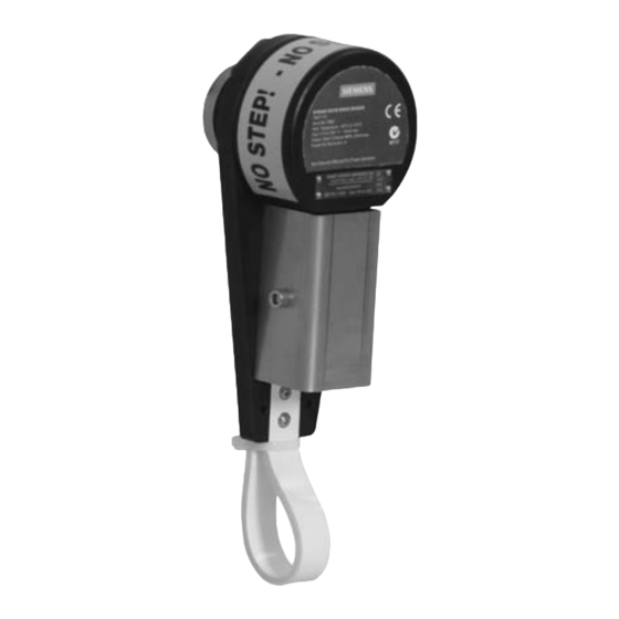
Note The Siemens speed sensor is to be used only in the manner outlined in this manual, otherwise protection provided by equipment may be impaired. This manual covers only speed sensor installation, operation, and maintenance procedures. It is... - Page 8 Introduction 1.1 SITRANS WS100 Speed Sensor The SITRANS WS100 IS (Intrinsically Safe) speed sensor contains a Pepperl + Fuchs, NAMUR rated, inductive proximity switch, model number: NCN4-12GM-35-N0. The proximity switch detects the pulses, and transmits a signal to the integrator via the associated Switch Isolator.
-
Page 9: Installing/Mounting
Polypropylene sealed housing for ferrous targets ② M20 (½" NPT) diameter hole for conduit adaptor (use flexible conduit) ③ Arrestor strap Figure 2-1 SITRANS WS100, dimensions in mm (in) Magnetic shaft connector option 53 (2.10) 31 (1.24) Ø 44 (1.75) (2.00) 203 (8.00) -
Page 10: Mounting
Male shaft connector, dimensions in mm (in) Mounting The input shaft on the SITRANS WS100 is coupled to the rotating shaft on a belt-driven pulley with a tapped hole, and is externally supported. The arresting strap prevents the unit rotating with the shaft, and can be attached to any rigid support member close to the sensor. - Page 11 When adjusting the belt take-up, ensure that the WS100 travels with the tail pulley bearing. "A" "A" View "A - A" ① Belt ② SITRANS WS100 ③ Cable ④ Arrestor strap (mounted to restraining bracket) ⑤ Restraining bracket (mounted off bearing)
- Page 12 Installing/mounting 2.2 Mounting Mounting to a bend or snub pulley Top view Front view ① Arrestor strap ② Conveyor stringer ③ Conveyor structure for arrestor strap ④ SITRANS WS100 ⑤ Belt SITRANS WS100 Operating Instructions, 06/2011, 7ML19985LU02-00...
-
Page 13: General Installation Steps
M12 x 1.75 .254 (.010) A Figure 2-4 Pulley shaft detail, dimensions in mm (in) 2. Thread the SITRANS WS100 onto the machine shaft using 16 mm or 5/8" open-ended wrench and releasable thread-locking adhesive (Loctite or similar). ① Lock against shaft 3. - Page 14 Installing/mounting 2.3 General Installation Steps SITRANS WS100 Operating Instructions, 06/2011, 7ML19985LU02-00...
-
Page 15: Connection
0.324 mm² (22 AWG) cable. To connect the SITRANS WS100 IS unit to the switch isolator, use two-wire shielded 0.324 mm² (22 AWG) cable. Use the same cable to connect the switch isolator to the integrator. -
Page 16: Terminal Connections To Siemens Integrators
Connection 3.2 Terminal connections to Siemens Integrators Wiring Note Ground the cable shield at the integrator end only! For optimal performance the stainless steel cover of the Speed Sensor must be connected to a reliable earthed ground. WS100 Standard: ●... -
Page 17: Terminal Connections To Siwarex Ftc Integrator
WS100 IS Isolation barrier Milltronics BW100 Milltronics BW500 SIWAREX FTC Note N/C indicates the terminal is not normally connected. For terminal connections to older model Siemens integrators consult your local Siemens representative. SITRANS WS100 Operating Instructions, 06/2011, 7ML19985LU02-00... - Page 18 Connection 3.3 Terminal connections to SIWAREX FTC Integrator SITRANS WS100 Operating Instructions, 06/2011, 7ML19985LU02-00...
-
Page 19: Service And Maintenance
Wear on the bearings is detected by excess play or sound. If the bearings exhibit excess play or produce an unreasonably loud sound, the speed sensor should be returned to Siemens for repair. Recommended spare parts ● Magnetic coupling ●... - Page 20 ● Information about field service, repairs, spare parts and lots more under "Services." Additional Support Please contact your local Siemens representative and offices if you have additional questions about the device Find your contact partner at: Local contact person (http://www.siemens.com/automation/partner)
-
Page 21: Technical Data
WS100 IS (Intrinsically Safe): Load current, 0 to 15 mA; Enclosure Polypropylene base and target enclosure with 304 (1.4301) stainless steel access cover 304 (1.4301) stainless steel shaft, bearings, and hardware Degree of protection: IP67 SITRANS WS100 Operating Instructions, 06/2011, 7ML19985LU02-00... - Page 22 Pepperl+Fuchs. For current approvals go to: http://www.am.pepperl-fuchs.com. Proximity Switch Approval Ratings (Pepperl+Fuchs #NCN4-12GM-35-N0) Hazardous: ATEX II 1D Ex iaD 20 T108 °C, ATEX II 1G EEx ia IIC T6 General purpose: CE , C-TICK, CSA/FM SITRANS WS100 Operating Instructions, 06/2011, 7ML19985LU02-00...
- Page 23 ATEX II 1G EEx ia IIC CSA: Class I, Div. 1, Groups A, B, C, and D, Class II, Div. 1, Groups E, F, and G, Class III General purpose: CE, C-TICK , FM SITRANS WS100 Operating Instructions, 06/2011, 7ML19985LU02-00...
- Page 24 Technical data SITRANS WS100 Operating Instructions, 06/2011, 7ML19985LU02-00...
- Page 26 For more information www.siemens.com/level www.siemens.com/weighing Siemens AG Subject to change without prior notice Industry Sector 7ML19985LU02 Rev. 2.0 1954 Technology Drive © Siemens AG 2011 P.O. Box 4225 *7ml19985LU02* Peterborough, ON Canada K9J 7B1 email: techpubs.smpi@siemens.com Printed in Canada www.siemens.com/processautomation...