Advertisement
Quick Links
Advertisement

Summary of Contents for Behringer VIRTUALIZER PRO DSP1000P
- Page 1 User´s Manual Bedienungsanleitung Get user manuals: See SafeManuals.com...
- Page 2 INTERNATIONAL GmbH acc. to the Directives 89/336/EWG and 73/23/EWG BEHRINGER INTERNATIONAL GmbH Hanns-Martin-Schleyer-Straße 36 - 38 D - 47877 Willich Name and address of the manufacturer or the introducer of the product on the market who is established in the EC herewith take the sole responsibility to confirm that the product: VIRTUALIZER PRO DSP1000P...
- Page 3 SAFETY INSTRUCTIONS Get user manuals: See SafeManuals.com...
- Page 4 VIRTUALIZER PRO Ultra-high performance Digital Multi-Effects Processor powered by a 24-bit high-speed Digital Signal Processor (DSP) Get user manuals: See SafeManuals.com...
- Page 5 FOREWORD Get user manuals: See SafeManuals.com...
-
Page 6: Table Of Contents
TABLE OF CONTENTS 1. INTRODUCTION ........................7 2. OPERATION ........................... 16 3. APPLICATIONS ........................19 4. TECHNICAL BACKGROUND ....................22 5. INSTALLATION ........................27 6. APPENDIX ..........................30 7. WARRANTY .......................... 35 Get user manuals: See SafeManuals.com... -
Page 7: Introduction
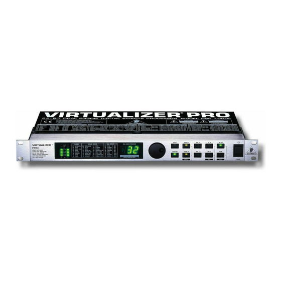
1. INTRODUCTION 1.1 The Design Concept Get user manuals: See SafeManuals.com... - Page 8 1.2 Before you begin 1.3 Control elements Fig. 1.1: VIRTUALIZER PRO front panel Get user manuals: See SafeManuals.com...
- Page 9 Fig. 1.2: Display section of the DSP1000P EFFECT TABLE Fig. 1.3: Function keys and jog wheel JOG WHEEL EFFECT Get user manuals: See SafeManuals.com...
- Page 10 VARIATION ENGINE L EDIT A EDIT B ENGINE R COUPLE EDIT A EDIT B EQ-LO IN/OUT STORE POWER before powering up External Mix Internal Mix Get user manuals: See SafeManuals.com...
- Page 11 OPERATING LEVEL INPUTS. OUTPUTS MIDI OUT / THRU / IN SERIAL NUMBER MAINS CONNECTOR / FUSE HOLDER / VOLTAGE SELECTOR. 1.4 The effect algorithms Get user manuals: See SafeManuals.com...
- Page 12 Get user manuals: See SafeManuals.com...
- Page 13 Get user manuals: See SafeManuals.com...
- Page 14 Get user manuals: See SafeManuals.com...
- Page 15 Get user manuals: See SafeManuals.com...
-
Page 16: Operation
2. OPERATION 2.1 Effects structure Fig. 2.1: Effects structure 2.2 Selecting presets Get user manuals: See SafeManuals.com... - Page 17 2.3 Editing programs 2.4 Saving programs before 2.5 MIDI control Get user manuals: See SafeManuals.com...
- Page 18 Dis play Mode No controller data are trans m itted Controller data are rec eived but not transm itted Controller data are trans mitted but not rec eived Controller data are trans mitted and rec eived Tab. 2.1: Controller settings Display Mode Program changes are not transmitted...
-
Page 19: Applications
3. APPLICATIONS 3.1 Level setting 3.2 Using the VIRTUALIZER PRO in the aux bus Fig. 3.1: Wiring aux busses Get user manuals: See SafeManuals.com... - Page 20 3.3 Using the VIRTUALIZER PRO in the insert path Channel Subgroup Insert Insert Fig. 3.2: Wiring the VIRTUALIZER PRO in the insert path Get user manuals: See SafeManuals.com...
- Page 21 3.4 Using the VIRTUALIZER PRO as an effects device for instruments Fig. 3.3: Connecting the VIRTUALIZER PRO to a guitar amp (send/return-mono) Get user manuals: See SafeManuals.com...
-
Page 22: Technical Background
3.5 Using the VIRTUALIZER PRO in a MIDI system Fig. 3.4: Connecting the VIRTUALIZER PRO via MIDI to a sequencer/computer and a keyboard (optional) 3.6 Saving data via MIDI 4. TECHNICAL BACKGROUND 4.1 Digital Audio Processing Get user manuals: See SafeManuals.com... - Page 23 U (Voltage) Quantization Steps Continuous 0111 Analog Signal 0110 0101 0100 0011 0010 0001 0000 t (Time) 1111 1110 1101 Quantization Errors 1100 (Noise) 1011 1010 1001 1000 Conversation Rate Digital Words Fig. 4.1: Transfer diagram for an ideal linear ADC (2’s complement representation) Get user manuals: See SafeManuals.com...
- Page 24 4.2 Reverberation and reflection Stage Listening Position Diffuse Reflections Fig. 4.2: Direct and reflected sounds reaching the listener’s ear Get user manuals: See SafeManuals.com...
- Page 25 Get user manuals: See SafeManuals.com...
- Page 26 Room Plate Speaker Sender Microphone Receiver Fig. 4.3: Room reflections and reverb plate reflections Get user manuals: See SafeManuals.com...
-
Page 27: Installation
5. INSTALLATION 5.1 Rack mounting 5.2 Mains connection 5.3 Audio connections Get user manuals: See SafeManuals.com... - Page 28 Output Cable Input Ground Pin 1 Shield (+) Signal + Hum Pin 2 = (+) Signal Positive (+)Hum + Signal (-) Signal + Hum Pin 3 = (-) Signal Negative (-)Hum + Signal 2 x Signal = Signal + 6 dB RFI and Hum Fig.
- Page 29 5.4 MIDI connections 5.5 Operating Level switch Get user manuals: See SafeManuals.com...
-
Page 30: Appendix
6. APPENDIX 6.1 Parameter overview Tab. 6.1: Parameter overview of the different effect types Get user manuals: See SafeManuals.com... - Page 31 6.2 Delay values / increments for presets 10 and 11 Variation Step Size Type Edit A (L & R) Delay (L) Delay (R) From (ms) Until (ms) From (ms) Until (ms) 1275 1275 1275 1275 1275 1280 1910 1920 2550 2560 3190 3200...
- Page 32 6.3 MIDI-implementation M IDI Implementation Chart Funktion Übe rtra ge n Erka nnt Be m e rkung Basic Default OFF, 1 - 16 OFF, 1 - 16 gespeichert Channel Changed OFF, 1 - 16 OFF, 1 - 16 Default 1,2,3,4 1,2,3,4 Mode Messages...
- Page 33 6.4 Default settings Engine Left Engine Right Effect Variation Edit A Edit B Edit A Edit B Cathedral Plate Small Hall Room Studio Concert Stage Vocal Percussion Delay Echo Gated Reverb Reverse Reverb Vocal Distortion Rotary Speaker Vocoder Pitch Flanger Chorus Tremolo &...
- Page 34 6.5 Specifications BEHRINGER is constantly striving to maintain the highest professional standards. As a result of these efforts, modifications may be made from time to time to existing products without prior notice. Specifications and appearance may differ from those listed or shown.
-
Page 35: Warranty
7. WARRANTY § 1 WARRANTY CARD § 2 WARRANTY § 3 RETURN AUTHORIZATION NUMBER BEHRINGER INTERNATIONAL GmbH Service Department § 5 WARRANTY TRANSFERABILITY Hanns-Martin-Schleyer-Str. 36-38 D - 47877 Willich-Münchheide § 4 WARRANTY REGULATIONS § 6 CLAIM FOR DAMAGES § 7 OTHER WARRANTY RIGHTS Get user manuals: See SafeManuals.com...


