Behringer Feedback Destroyer Pro DSP1124P User Manual
Hide thumbs
Also See for Feedback Destroyer Pro DSP1124P:
- Technical specifications (4 pages) ,
- Manual (26 pages)

Related Manuals for Behringer Feedback Destroyer Pro DSP1124P


Summary of Contents for Behringer Feedback Destroyer Pro DSP1124P
- Page 1 Downloaded from www.g7syw.com User’s Manual Version 1.0 February 2001 www.behringer.com www.g7syw.com...
- Page 2 Downloaded from www.g7syw.com FEEDBACK DESTROYER PRO DSP1124P SAFETY INSTRUCTIONS CAUTION: To reduce the risk of electrical shock, do not remove the cover (or back). No user serviceable parts inside; refer servicing to qualified personnel. WARNING: To reduce the risk of fire or electrical shock, do not expose this appliance to rain or moisture.
- Page 3 It is our philosophy to share our joy with you, because you are the most important member of the BEHRINGER family. With your highly competent suggestions for new products you’ve greatly contributed to shaping our company and making it successful.
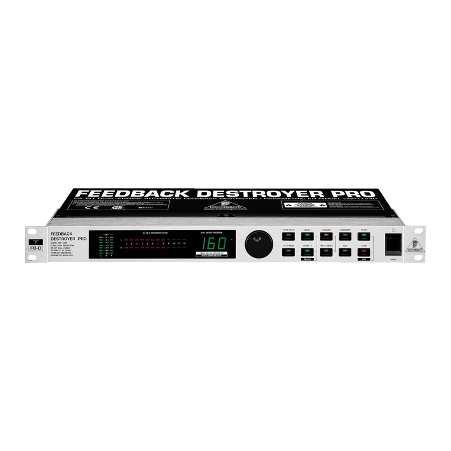
- Page 4 Downloaded from www.g7syw.com FEEDBACK DESTROYER PRO DSP1124P FEEDBACK DESTROYER ® 24-Bit Dual Engine Digital Feedback Destroyer / Parametric EQ Model DSP1124P s Ultra-high performance 2-channel digital Feedback Destroyer / parametric EQ powered by a 24-bit high-speed DSP s 24-bit A/D and D/A converters with 64/128 times oversampling for ultra-high headroom and resolution s Automatically and “intelligently”...
-
Page 5: Table Of Contents
Downloaded from www.g7syw.com FEEDBACK DESTROYER PRO DSP1124P TABLE OF CONTENTS 1. INTRODUCTION ........................6 1.1 The design concept ......................... 6 1.2 Before you begin ..........................6 1.3 Background: How is feedback produced? ..................7 1.3.1 Background: front of house mix (FOH) .................. 7 1.3.2 Background: monitor mix ...................... -
Page 6: Introduction
Shipping claims must be made by the consignee. The BEHRINGER FEEDBACK DESTROYER PRO requires one standard 19" unit of rack space. Please allow at least an additional 4" depth for the connectors on the back panel. -
Page 7: Background: How Is Feedback Produced
As a standard, the BEHRINGER FEEDBACK DESTROYER PRO is equipped with electronically servo-balanced inputs and outputs. The circuit design features automatic hum and noise reduction for balanced signals and thus allows for trouble-free operation, even at high operating levels. -
Page 8: Applications
Before you go on, please note the following two remarks: The FEEDBACK DESTROYER PRO is not intended to be connected directly to the microphones! If this is unavoidable, then we recommend our proven BEHRINGER SHARK DSP110 instead, which is equipped with a dedicated microphone preamplifier. -
Page 9: Using The Feedback Destroyer Pro In The Foh Mix
Downloaded from www.g7syw.com FEEDBACK DESTROYER PRO DSP1124P Fig. 2.1: Using the DSP1124P in the monitor sends 2.3 Using the FEEDBACK DESTROYER PRO in the FOH mix Since you want to make sure that deliberately produced feedback signals, such as “guitar feedback”, are not eliminated, you should try inserting the DSP1124P into those channels that are susceptible to feedback. -
Page 10: Using The Feedback Destroyer Pro In A Studio Environment
But don’t let us do the second step before the first: 4. CONTROL ELEMENTS The BEHRINGER FEEDBACK DESTROYER PRO is equipped with ten parameter keys, one JOG WHEEL (rotary control) and a numeric LED DISPLAY. By means of an 8-segment LED meter, each of the two fully independent channels can be monitored. - Page 11 Downloaded from www.g7syw.com FEEDBACK DESTROYER PRO DSP1124P s A filter has been “set”, i.e. it is already suppressing feedback; or: s A filter is set to Parametric EQ mode (gain ¹ 0 dB). Cyclically flashing LEDs signal that a filter is searching feedback frequencies in Single-Shot or Auto mode (see chapters 5 and 6.3).
- Page 12 Or use our online registration option available on the World Wide Web at www.behringer.com. The DSP1124P features a complete set of MIDI functions. In addition to the usual MIDI IN and MIDI OUT ports, the MIDI THRU allows you to loop through MIDI data.
-
Page 13: Dsp1124P Architecture: Presets, Filters, Operating Modes
Downloaded from www.g7syw.com FEEDBACK DESTROYER PRO DSP1124P 5. DSP1124P ARCHITECTURE: PRESETS, FILTERS, OPERATING MODES In order to avoid confusion, let us give you a concise description of the DSP1124P’s operating principle, so as to make the three relevant points clear right from the start. Example: You have set up your P.A. system and connected all signal sources to the console. -
Page 14: Operating Modes Of The Dsp1124P
FEEDBACK DESTROYER PRO DSP1124P 6. OPERATING MODES OF THE DSP1124P The individual filters on the BEHRINGER FEEDBACK DESTROYER PRO can operate in four different modes (see ). An additional mode called “Locked” mode will be described specifically. Basically, each of the 2 x 12 filters on the DSP1124P can be set to any of the four operating modes. -
Page 15: Locked Mode (“Lo”)
Downloaded from www.g7syw.com FEEDBACK DESTROYER PRO DSP1124P 6.4 Locked mode (“LO”) When the DSP1124P detects a feedback frequency in Single-Shot mode (see chapter 6.3), it automatically enters Locked mode, i.e. the filter locks to the trouble frequency and “keeps an eye” on it. To unlock such a filter, you need to switch it back to Single-Shot mode (see and chapter 7.2). -
Page 16: Editing Filter Parameters
Downloaded from www.g7syw.com FEEDBACK DESTROYER PRO DSP1124P To avoid inadvertent changing of filter modes, the filter mode selection takes place after about one second, which is indicated by a dot in the lower right corner of the DISPLAY. Press the FILTER MODE and GAIN keys at the same time, and use the JOG WHEEL to adjust the feedback threshold (= feedback sensitivity) within a range from -3 to -9 dB. -
Page 17: Problems Do Have A Cause
Downloaded from www.g7syw.com FEEDBACK DESTROYER PRO DSP1124P 8. PROBLEMS DO HAVE A CAUSE ... Feedback is one of the major problems encountered in live P.A. applications. In a worst-case scenario every microphone signal passing an amplifier can cause feedback. Still, there’s a lot you can do even before the show begins: s Place the microphones at some distance to the FOH and monitor speakers. -
Page 18: Installation
The FEEDBACK DESTROYER Design Editor software enables you to control the DSP1124P from an external PC. What is more, you can use the FEEDBACK DESTROYER PRO to control the editor software, so that both units communicate with each other. Download the editor free of charge from our web site at www.behringer.com. 10. INSTALLATION 10.1 Audio connections... - Page 19 Downloaded from www.g7syw.com FEEDBACK DESTROYER PRO DSP1124P Fig. 10.1: Different plug types Fig. 10.2: Wiring an insert cable Please ensure that only qualified persons install and operate the FEEDBACK DESTROYER PRO. During installation and operation the user must have sufficient electrical contact to earth.
-
Page 20: Midi Connections
Downloaded from www.g7syw.com FEEDBACK DESTROYER PRO DSP1124P 10.2 MIDI connections The MIDI connectors found on the rear panel are on internationally standardized 5-pin DIN jacks. You need dedicated MIDI cables to connect the FEEDBACK DESTROYER PRO to other MIDI equipment. Normally, complete cables will be purchased for this use, but you can also make your own, using a high-quality two-conductor shielded cables (e.g. -
Page 21: Preset Table
Downloaded from www.g7syw.com FEEDBACK DESTROYER PRO DSP1124P − ∆ f increment 31.5 40 100 125 160 200 250 315 400 500 630 800 1.25 1.6 2.5 3.15 12.5 16 Tab. 11.2: Standard ISO frequencies 11.2 Preset table Preset Filter 1... -
Page 22: Midi Implementation
Downloaded from www.g7syw.com FEEDBACK DESTROYER PRO DSP1124P 11.3 MIDI implementation Function Transmitted Recognized Remark s Basic Default OFF, 1 - 16 OFF, 1 - 16 memorized Channel Changed OFF, 1 - 16 OFF, 1 - 16 Default 1,2,3,4 1,2,3,4 Mode... -
Page 23: Specifications
3 kg BEHRINGER is constantly striving to maintain the highest professional standards. As a result of these efforts, modifications may be made from time to time to existing products without prior notice. Specifications and appearance may differ from those listed or illustrated. -
Page 24: Warranty
(user included) will void the warranty. at its sole discretion, either repair or replace the product. 6. If an inspection of the product by BEHRINGER shows that the 2. If the warranty claim proves to be justified, the product will be defect in question is not covered by the warranty, the inspection returned to the user freight prepaid.