Table of Contents
Advertisement
Quick Links
Advertisement
Table of Contents

Related Manuals for IBM ServeRAID M5025


Summary of Contents for IBM ServeRAID M5025
- Page 1 ® USER’S GUIDE ServeRAID M5025 SAS/SATA Controller S e p t e m b e r 2 0 1 1...
- Page 2 Second Edition (September 2011) © Copyright International Business Machines Corporation 2011. All rights reserved. US Government Users Restricted Rights – Use, duplication or disclosure restricted by GSA ADP Schedule Contract with IBM Corp.
- Page 3 Engineers who are designing a system that will include the ServeRAID M5025 SAS/SATA controller Anyone installing the ServeRAID M5025 SAS/SATA controller in a RAID system End users who need to install the iBBU product on the ServeRAID M5025 SAS/SATA controller ...
- Page 4 End users who need to install a ServeRAID M5000 Series Advanced Feature Key on a ServeRAID M5025 SAS/SATA controller Organization This document has the following chapters and appendices: Chapter 1, Overview, provides a general overview of the ServeRAID M5025 SAS/SATA controller.
- Page 5 IBM Systems Safety Notices IBM Document Number: G229-9054-01 This book contains safety notices from IBM Systems documentation. The safety notices include danger and caution notices. Notices and Statements in This Document The caution and danger statements in this document are also in the multilingual IBM Systems Safety Notices document, which is on the ServeRAID-MR Documentation CD.
- Page 6 Safety Instructions Use the following safety guidelines to help protect your computer system from potential damage and to ensure your own personal safety. Note: Use the ServeRAID M5025 SAS/SATA controller with UL-listed Information Technology Equipment (ITE) products only. Preface...
- Page 7 DANGER When working on or around the system, observe the following precautions: Electrical voltage and current from power, telephone, and communication cables are hazardous. To avoid a shock hazard: Connect power to this unit only with the provided power cord. Do not use the provided power cord for any other product.
- Page 8 In the United States, IBM has a process for the collection of this battery. For information, call 1-800-426- 4333. Have the IBM part number for the battery unit available when you call. (C007) Protecting against Electrostatic Discharge – Static electricity can harm delicate components inside your computer.
-
Page 9: Table Of Contents
General Description Configuration Scenarios 1.4.1 Number of Physical Disks Supported Benefits of the SAS Interface 1.5.1 PCI Express Architecture 1.5.2 Operating System Support Summary of the ServeRAID M5025 SAS/SATA Controller Characteristics 1.6.1 SAS Features 1-10 1.6.2 SAS Array Limitations 1-10 1.6.3... - Page 10 Detailed Installation After Installing the Controller Connecting the ServeRAID M5025 Controller to a Drive Enclosure Replacing a Failed Controller Containing Data in the iBBU Chapter 3 ServeRAID M5025 SAS/SATA Controller Characteristics ServeRAID M5025 SAS/SATA Controller 3.1.1 Board Layout and Connector Information...
- Page 11 Intelligent Battery Backup Unit Specifications Battery Life and Data Retention Time Chapter 8 Installing a ServeRAID M5000 Series Advanced Feature Key Installing the ServeRAID M5000 Series Advanced Feature Key on the ServeRAID M5025 SAS/SATA Controller Appendix A Notices Trademarks Important Notes...
- Page 12 Contents...
- Page 13 Example of a SAS Direct-Connect Application Example of a SAS RAID Controller Configured with an LSISASx12 Expander ServeRAID M5025 Controller Installation in a PCI Express Slot Connecting the ServeRAID M5025 Controller to a Drive Enclosure Card Layout for the ServeRAID M5025 RAID Controller...
- Page 14 Contents...
- Page 15 Tables Physical Devices Required for Each RAID Level ServeRAID M5025 SAS/SATA Controller Array Limitations 1-10 ServeRAID M5025 SAS/SATA Controller Specifications 1-15 ServeRAID M5025 SAS/SATA Controller – Connectors ServeRAID M5025 SAS/SATA Controller Characteristics ServeRAID M5025 SAS/SATA Controller Specifications Array Performance Features...
- Page 16 Contents...
-
Page 17: Overview
Section 1.8, “Technical Support” Overview The ServeRAID M5025 Serial Attached SCSI (SAS)/Serial ATA II (SATA II) controller is a high-performance intelligent PCI Express-to-SAS/SATA II adapter with RAID control capabilities. The ServeRAID M5025 controller provides reliability, high performance, and fault-tolerant disk subsystem management. - Page 18 (SATA II) protocol defined by the Serial ATA Specification, Version 1.0a, and the Serial ATA II; Extension to the Serial ATA Specification, Version 1.1. SATA II is an extension to SATA 1.0a. The ServeRAID M5025 controller is a versatile controller that provides the backbone of both server and high-end workstation environments.
-
Page 19: Serveraid M5025 Sas/Sata Controller Description And Limitations
SATA II device through an attached expander ServeRAID M5025 SAS/SATA Controller Description and Limitations The ServeRAID M5025 controller is available with eight PHYs. The controller has one LSISAS2108 ROC (RAID-on-chip) processor that controls eight external SAS/SATA ports through two x4 SAS external connectors. -
Page 20: General Description
General Description The ServeRAID M5025 controller brings 6.0 Gbit/s Serial Attached SCSI (SAS) and 3.0 Gbit/s Serial ATA II (SATA II) performance to host adapter, workstation, and server designs. The controller supports external storage devices, which allows you to use a system that supports enterprise-class SAS drives, and desktop-class SATA II drives. -
Page 21: Configuration Scenarios
Activity and fault indicators for each PHY Port Selector (for dual-port drives) Each port on the ServeRAID M5025 controller supports SAS devices, SATA II devices, or both using SSP, SMP, STP, and SATA II. SSP enables communication with other SAS devices. SATA II enables the controller to communicate with other SATA II devices. -
Page 22: Example Of A Sas Direct-Connect Application
Interface SAS/SATA II Device PCI Express Interface Figure 1.2 shows an example of the ServeRAID M5025 controller configured with an LSISASx12 expander that is connected to SAS disks, SATA II disks, or both. Figure 1.2 Example of a SAS RAID Controller Configured with an... -
Page 23: Number Of Physical Disks Supported
1.4.1 Number of Physical Disks Supported Your configuration planning for the ServeRAID M5025 controller depends in part on the number of physical disks that you want to use in a RAID array. The number of drives in an array determines the RAID levels that can be supported by this controller. -
Page 24: Pci Express Architecture
PCI Express is a local bus system designed to increase data transfers without slowing down the central processing unit (CPU). You can install the ServeRAID M5025 PCI Express RAID controller in PCI Express computer systems with a standard bracket type. With these adapters in your system, you can connect SCSI devices and SATA II devices over the bus. -
Page 25: Summary Of The Serveraid M5025 Sas/Sata Controller Characteristics
The ServeRAID M5025 controllers use Fusion-MPT™ architecture for all major operating systems, thinner drivers, and better performance. Summary of the ServeRAID M5025 SAS/SATA Controller Characteristics This section provides a summary of the features and benefits of the ServeRAID M5025 controller controller. It contains information on SAS features, SATA II features, PCI performance, integration, usability, and flexibility. -
Page 26: Sas Features
1.6.1 SAS Features The following list describes the SAS features of the ServeRAID M5025 controller: Provides eight fully independent PHYs Supports 6.0 Gbit/s SAS data transfers per PHY Supports SSP to enable communication with other SAS devices ... -
Page 27: Sata Ii Features
16 arrays per controller. In addition, though you can have up to 16 virtual disks in an array, and up to 16 arrays per ServeRAID M5025 controller, there is a limit of 64 virtual disks per controller. -
Page 28: Pci Express Performance
Provides up to two LED signals for each PHY to indicate link activity and faults Provides an I C interface for enclosure management Supports the external SAS Sideband signal SFF-8485 (SGPIO) interface 1.6.6 Flexibility Features These features increase the flexibility of the ServeRAID M5025 controller: 1-12 Overview... -
Page 29: Drive Roaming
Step 2. Open the host system by following the instructions in the host system technical documentation. Step 3. Move the drives to different positions on the backplane to change the targets. Step 4. Determine the SAS target requirements. Summary of the ServeRAID M5025 SAS/SATA Controller Characteristics 1-13... -
Page 30: Drive Migration
Step 5. Perform a safety check. a. Make sure that the drives are inserted correctly. b. Close the cabinet of the host system. Step 6. Reconnect the power cords to the system. Step 7. Turn on the power to the system. The controller then detects the RAID configuration from the configuration data on the drives. -
Page 31: Hardware Specifications
Step 10. Turn on the power to the system. The controller detects the RAID configuration from the configuration data on the drives. Hardware Specifications You can install the ServeRAID M5025 controller in a computer with a mainboard that has a PCI Express slot. Table 1.3 describes the hardware configuration features for the ServeRAID M5025 controller. -
Page 32: Technical Support
Table 1.3 ServeRAID M5025 SAS/SATA Controller Specifications (Cont.) Specification ServeRAID M5025 SAS/SATA Controller PCI Express Rev 2.0 Cache Function Write-back, write-through, adaptive read ahead, non-read ahead, read ahead, cache I/O, direct I/O Multiple Virtual Disks/ Up to 40 virtual disks per controller or per logical array... -
Page 33: Serveraid M5025 Sas/Sata Controller Hardware Installation
Section 2.2, “Quick Installation” Section 2.3, “Detailed Installation” Section 2.4, “After Installing the Controller” Section 2.5, “Connecting the ServeRAID M5025 Controller to a Drive Enclosure” Section 2.6, “Replacing a Failed Controller Containing Data in the iBBU” Requirements The following items are required for installation: ... -
Page 34: Quick Installation
Step 3. Check the intelligent Battery Backup Unit (iBBU) on the controller. Step 4. Install the ServeRAID M5025 controller in the server and connect the SAS devices or the SATA II devices to it. Make sure that the cables you use conform to all specifications. - Page 35 Before you install the controller, make sure that the computer is disconnected from the power and from any networks. Step 3. Review the ServeRAID M5025 Controller Connectors Refer to Chapter 3, “ServeRAID M5025 SAS/SATA Controller Characteristics”...
-
Page 36: Serveraid M5025 Controller Installation In A Pci Express Slot
Step 8. Connect the SAS Devices, the SATA II Devices, or Both to the Controller Use SAS cables to connect SAS devices, SATA II devices, or both to the ServeRAID M5025 controller. Refer to Section 2.5, “Connecting the ServeRAID M5025 Controller to a Drive... - Page 37 The configuration utility prompt times out after several seconds. The second portion of the BIOS message displays the ServeRAID M5025 controller number, firmware version, and cache SDRAM size. The numbering of the controller follows the PCI slot scanning order used by the host mainboard.
- Page 38 Device Driver Installation User’s Guide on the ServeRAID-MR Documentation CD. After Installing the Controller After the ServeRAID M5025 controller installation, you must configure the controller and install the operating system driver. The ServeRAID-MR Software User’s Guide instructs you on the configuration options and how to set them on your controller.
-
Page 39: Connecting The Serveraid M5025 Controller To A Drive Enclosure
If the power failure results from the failure of the ServeRAID M5025 controller, then you can move the iBBU to a new controller and recover the data. The replacement controller must have a cleared configuration. - Page 40 The battery is a lithium ion battery. To avoid possible explosion, do not burn. Exchange only with the IBM-approved part. Recycle or discard the battery as instructed by local regulations. In the United States, IBM has a process for the collection of this battery. For information, call 1-800-426- 4333.
-
Page 41: Serveraid M5025 Sas/Sata Controller Characteristics
Section 3.3, “Technical Specifications” ServeRAID M5025 SAS/SATA Controller The ServeRAID M5025 SAS/SATA controller is a dual PHY, SAS PCI Express adapter and is used in a system with a PCI Express slot. PCI Express goes beyond the PCI specification in that it is intended as a unifying I/O architecture for various systems: desktops, workstations, mobile, server, communications, and embedded devices. -
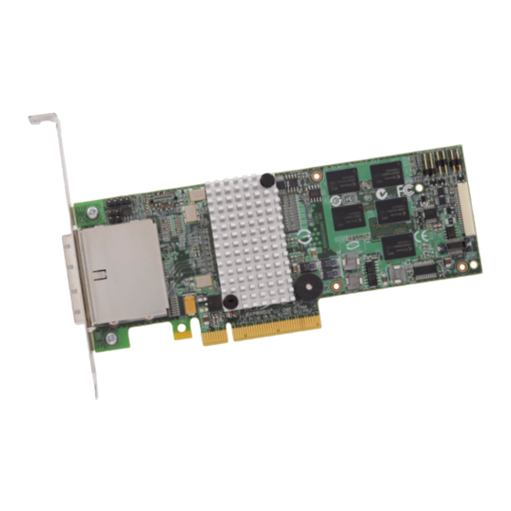
Page 42: Card Layout For The Serveraid M5025 Raid Controller
Figure 3.1 Card Layout for the ServeRAID M5025 RAID Controller J6A2 J6A1 J6A3 J1A1 J1A2 J1A4 Port J6B1 J1B1 J6B2 Port 85040-07 Table 3.1 ServeRAID M5025 SAS/SATA Controller – Connectors Connector Description Type Comments J1A1 Universal 4-pin Reserved for IBM use. - Page 43 Activity LED For boot code and firmware. For BIOS configuration storage. The ServeRAID M5025 controller ensures data integrity by intelligently validating the compatibility of the SAS domain. The controller uses Fusion-MPT architecture, which allows for thinner drivers and better performance.
- Page 44 Japan VCCI In addition, the controller meets the requirements of CISPR Class B. The ServeRAID M5025 SAS/SATA controller and the intelligent Battery Backup Unit (iBBU) are CSA C22.2 No. 60950-1, UL 60950-1 First Edition listed Accessory, UL file number E257743.
-
Page 45: Serveraid M5025 Sas/Sata Controller
8 Kbytes, 16 Kbytes, 32 Kbytes, 64 Kbytes, 128 Kbytes, 256 Kbytes, 512 Kbytes, or 1 Mbyte Maximum Number of Concurrent Commands Support for Multiple Initiators 3.3.3 Fault Tolerance Table 3.5 shows the fault tolerance features of the ServeRAID M5025 SAS/SATA controller. Technical Specifications... -
Page 46: Fault Tolerance Features
Power Supply Requirements for the ServeRAID M5025 SAS/SATA Controller All power is supplied to the ServeRAID M5025 SAS/SATA controller through the PCI Express 3.3V rails and the 12V rail. Onboard switching regulator circuitry operating from the 3.3V rails and the 12V rail provide the necessary voltages. -
Page 47: Power Supply For The Serveraid M5025 Controller
Temperature range: 10C to +45C with iBBU battery backup 3.3.6 Safety Characteristics The ServeRAID M5025 SAS/SATA controller meets or exceeds the requirements of UL flammability rating 94 V0. Each bare board is also marked with the supplier name or trademark, type, and UL flammability rating. - Page 48 ServeRAID M5025 SAS/SATA Controller Characteristics...
- Page 49 The iBBU monitors the voltage level of the DRAM modules installed on the ServeRAID M5025 controller. If the voltage drops below a predefined level, the battery backup module switches the memory power source from the controller to the battery pack attached to the iBBU. As long as the voltage level stays below the predefined value, the iBBU provides power for memory.
- Page 50 The battery is a lithium ion battery. To avoid possible explosion, do not burn. Exchange only with the IBM-approved part. Recycle or discard the battery as instructed by local regulations. In the United States, IBM has a process for the collection of this battery. For information, call 1-800-426- 4333.
- Page 51 Installing the Intelligent Battery Backup Unit This chapter explains how to install the intelligent Battery Backup Unit (iBBU) on the ServeRAID M5025 SAS/SATA Controller. Attention: Electrostatic discharge can damage the iBBU and the controller on which it is installed. Always ground yourself and/or use a ground strap before you touch the controller or the iBBU.
-
Page 52: Intelligent Battery Backup Unit
ServeRAID M5025 Controller The iBBU is compatible with systems that offer auxiliary power. Battery charging and recharging take place automatically. The iBBU mounts directly to the ServeRAID M5025 controller using a small board-to-board connector (daughtercard). Figure 5.1 displays the top view and the bottom view of the card. (The “top”... - Page 53 The battery is a lithium ion battery. To avoid possible explosion, do not burn. Exchange only with the IBM-approved part. Recycle or discard the battery as instructed by local regulations. In the United States, IBM has a process for the collection of this battery. For information, call 1-800-426- 4333.
-
Page 54: Installing The Ibbu Daughtercard On The Serveraid M5025 Sas/Sata Controller
Figure 5.2 Installing the iBBU Daughtercard on the ServeRAID M5025 SAS/SATA Controller 85041-04 J6B2 4. Carefully press the iBBU onto the controller, so that the two connectors are firmly joined. 5. Secure the iBBU to the controller with the screws and the standoffs in the three screwholes. -
Page 55: Installing The Serveraid M5025 Sas/Sata Controller
SAS/SATA Controller You can use the supplied 20-pin cable to connect the iBBU remotely to the ServeRAID M5025 controller. Follow these steps to install the iBBU remotely to the controller. 1. Ground yourself, and remove the iBBU from the package. -
Page 56: Connecting The Ibbu Remotely To The Serveraid M5025 Sas/Sata Controller
3. Insert the battery pack harness at the end of the 5-pin cable into the J4 connector on the backside of the iBBU. 4. Use the supplied 20-pin, 10-inch cable to connect the J2 connector on the iBBU to the J6B1 BBU connector on the controller, as shown Figure 5.4. - Page 57 Battery Backup Unit This chapter explains how to monitor and maintain the iBBU for your ServeRAID M5025 SAS/SATA controller. Most of the iBBU functions, such as battery recharging, occur automatically. Click on the following links to view instructions on how to use the iBBU: ...
- Page 58 Monitoring the IBBU with the MegaRAID Configuration Utilities This section describes the MegaRAID configuration utilities you can use to monitor the condition of the installed iBBU and to change the automatic learn mode options. They include the WebBIOS Configuration Utility, MegaCLI, and MegaRAID Storage Manager. 6.1.1 Monitoring the iBBU with the WebBIOS Configuration Utility The WebBIOS CU is a web-based utility for configuring and managing...
-
Page 59: First Controller Properties Screen
Figure 6.1 First Controller Properties Screen 4. Click Next to view the second Controller Properties screen. The second Controller Properties screen appears, as shown in Figure 6.2. The Battery Backup field at the top left of the screen indicates whether the iBBU is present. Monitoring the IBBU with the MegaRAID Configuration Utilities... -
Page 60: Second Controller Properties Screen
Figure 6.2 Second Controller Properties Screen 5. Click Present in the Battery Backup field. The Battery Module screen appears, as shown in Figure 6.3. This screen contains the following information: – Battery information – Design information – Capacity information – Auto Learn properties and settings Using the Intelligent Battery Backup Unit... -
Page 61: Battery Module Screen
Figure 6.3 Battery Module Screen Most of the Battery Module properties are view-only and are self- explanatory. In the lower right corner of the screen are the Auto Learn options. A learning cycle is a battery calibration operation performed by the controller periodically to determine the condition of the battery. -
Page 62: Monitoring The Ibbu With The Megacli Utility
You can delay the start of the learn cycles for up to 168 hours (7 days). 4. Click Go. 6.1.1.2 Setting the Learn Mode You can start battery learning cycles manually or automatically. The Auto Learn modes are: – BBU Auto Learn: Firmware tracks the time since the last learning cycle and performs a learn cycle when due. -
Page 63: Display Bbu Status Information
Table 6.1 Display BBU Information Convention MegaCli -AdpBbuCmd -aN|-a0,1,2|-aALL Description Displays complete information about the BBU, such as status, capacity information, design information, and properties. 6.1.2.2 Display BBU Status Information Use the command in Table 6.2 to display complete information about the status of the BBU, such as temperature and voltage, for the selected controller(s). -
Page 64: Display Bbu Capacity
Table 6.2 Display BBU Status Information Description Displays complete information about the BBU status, such as the temperature and voltage. The information displays in the following formats: BBU Status for Adapter: xx Battery Type: XXXXXX(string) Voltage: xx mV Current: xx mA Temperature: xx C°... -
Page 65: Display Bbu Design Parameters
Table 6.3 Display BBU Capacity Information (Cont.) Description Displays BBU capacity information. The information displays in the following format: BBU Capacity Info for Adapter: x Relative State of Charge: xx% Absolute State of Charge: xx% Remaining Capacity: xx mAh Full Charge Capacity: xx mAh Run Time to Empty: xxx Min Average Time to Empty: xxx Min Average Time to Full: xxx Min... -
Page 66: Start Bbu Learning Cycle
Table 6.5 Display Current BBU Properties (Cont.) Description Displays current properties of the BBU. The information displays in the following formats: BBU Properties for Adapter: x Auto Learn Period: xxx Sec Next Learn Time: xxxx Sec Learn Delay Interval=<value>: Value in hours, not greater than 168 hours (7 days) Auto-Learn Mode=<value>: Value can be 0, 1, or 2. -
Page 67: Monitoring The Ibbu With The Megaraid Storage Manager
Table 6.8 Set BBU Properties (Cont.) Description Sets the BBU properties on the selected controller(s) after reading from the file. The information displays in the following formats: autoLearnPeriod = 1800Sec nextLearnTime = 12345678Sec Seconds past 1/1/2000 learnDelayInterval = 24hours Not greater than 7 days autoLearnMode = 0 0 –... -
Page 68: Setting The Learn Cycle Properties
you can start the learn cycles manually, and you can choose to receive a reminder to start a manual learn cycle. 6.1.3.2 Setting the Learn Cycle Properties To set the learn cycle properties, perform the following steps: 1. Click the Physical tab to open the physical view. 2. -
Page 69: Replacing The Battery Backup Unit
The battery is a lithium ion battery. To avoid possible explosion, do not burn. Exchange only with the IBM-approved part. Recycle or discard the battery as instructed by local regulations. In the United States, IBM has a process for the collection of this battery. For information, call 1-800-426- 4333. - Page 70 This gives you the option to view both the configuration on the NVRAM and the physical disk. 3. Select the configuration on the drive. 4. Press ESC, and select YES to update the NVRAM. 5. Press ESC to exit, and then reboot the computer. 6-14 Using the Intelligent Battery Backup Unit...
-
Page 71: Intelligent Battery Backup Unit Specifications
> 90 days: 0 to 30 °C Table 7.1 Intelligent Battery Backup Unit Specifications iBBU Fast Charge Rate 230 mAH Battery Pack 1 cell Mechanical 2.611” x 2.122” Battery Capacity 1400 mAH Charge Circuitry Card Memory Technology DDR2 SDRAM (1.8V) ServeRAID M5025 SAS/SATA Controller User’s Guide... -
Page 72: Battery Life And Data Retention Time
For instructions on installing the iBBU, see Section 5.1, “Installing the iBBU on the ServeRAID M5025 Controller.” For optimal performance, replace the battery backup unit once a year. The data retention time shown in Table 7.2... -
Page 73: Installing A Serveraid M5000 Series Advanced Feature Key
Feature Key on the ServeRAID M5025 SAS/SATA Controller Perform the following steps to install the ServeRAID M5000 Series Advanced Feature Key directly to the ServeRAID M5025 SAS/SATA controller. 1. Turn off the computer and unplug the power cords from the rear of the power supply. -
Page 74: Installing The Serveraid M5000 Series Advanced Feature Key On The M5025 Serveraid Sas/Sata Controller
2. Remove the cover from the computer according to the instructions in the system user’s manual so you can access the controller. Note: When handling static sensitive devices, take precautions to avoid damage from static electricity. 3. Ground yourself before you touch the controller or the Advanced Feature Key. -
Page 75: Appendix A Notices
Consult your local IBM representative for information on the products and services currently available in your area. Any reference to an IBM product, program, or service is not intended to state or imply that only that IBM product, program, or service may be used. -
Page 76: A.1 Trademarks
Web sites. The materials at those Web sites are not part of the materials for this IBM product, and use of those Web sites is at your own risk. -
Page 77: A.2 Important Notes
These products are offered and warranted solely by third parties. IBM makes no representations or warranties with respect to non-IBM products. Support (if any) for the non-IBM products is provided by the third party, not IBM. Some software might differ from its retail version (if available) and might not include user manuals or all program functionality. - Page 78 Notices...
-
Page 79: Appendix B Glossary Of Terms And Abbreviations
Fusion-MPT Fusion-MPT (Message Passing Technology) architecture consists of architecture several main elements: Fusion-MPT firmware, the Fibre Channel and SCSI hardware, and the operating system level drivers that support ServeRAID M5025 SAS/SATA Controller User’s Guide... - Page 80 these architectures. Fusion-MPT architecture offers a single binary, operating system driver that supports both Fibre Channel and SCSI devices. host The computer system in which a storage adapter is installed. It uses the storage adapter to transfer information to and from devices attached to the SCSI bus.
- Page 81 Serial ATA Specification, Version 1.0a, and the Serial ATAII; Extension to the Serial ATA Specification, Version 1.1. SATA II is an extension to SATA 1.0a. The ServeRAID M5025 SAS/SATA controller is a versatile controller that provides the backbone of both server and high-end workstation...
- Page 82 environments. Each port on the RAID controller supports SAS devices and/or SATA II devices. SAS device Any device that conforms to the SAS standard and is attached to the SAS bus by a SAS cable. This includes SAS storage adapters (host adapters) and SAS peripherals.
- Page 83 a stripe is the same on each disk included in the stripe. The portion of a stripe that resides on a single disk is a stripe element. Striping by itself does not provide data redundancy; striping in combination with parity provides data redundancy.
- Page 84 Glossary of Terms and Abbreviations...
- Page 86 Part number: 60Y1428 ®...