Shure ULX Wireless ULXP4,ULXS4 Manual
- User manual (52 pages) ,
- Manual (31 pages) ,
- User manual supplement (20 pages)
Advertisement
- 1 ULX System Components
- 2 Antennas
- 3 Rack Installation
- 4 Rackmount Options
- 5 Power
- 6 Batteries
- 7 Single System
- 8 Multiple Systems
- 9 Automatic Frequency Scan
- 10 Changing Group and Channel
- 11 Wireless Indicators
- 12 Frequency Master List Mode
- 13 Squelch (ULXP4 Only)
- 14 Audio Output
- 15 Receiver Output Level
- 16 PEAK Icon
- 17 Transmitter Gain
- 18 Locking the Receiver (ULXP4 Only)
- 19 Locking the Transmitter
- 20 Troubleshooting
- 21 Tips for Improving System Performance
- 22 Parts and Accessories
- 23 Certifications
- 24 Important Product Information
- 25 Wiring Diagram
- 26 Specifications
- 27 Frequencies for European Countries
- 28 Videos
- 29 Documents / Resources
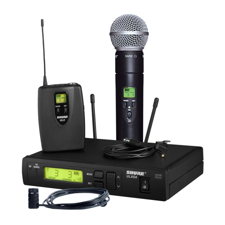
ULX System Components
All systems include either a ULXS4 Standard Diversity Receiver or ULXP4 Professional Diversity Receiver.
Bodypack systems include a choice of lavalier, headworn, or instrument microphones.
WB98H/C
WH30, WCM16, WBH53/54
WL93, WL183/184/185, WL50/51
Handheld systems include a choice of interchangeable microphone heads.
SM58, SM86, SM87A, Beta 58, Beta 87C
Guitar systems include a 1/4" to mini 4-pin cable.
WA302
ULXP4 receivers include rack-mounting hardware.
UA507
FULL RACK MOUNT HARDWARE
UA506
1/2 RACK MOUNT HARDWARE
Antennas
Active Antennas
The antenna connectors on the ULX receiver provide 12 V DC for active circuit antennas.
Caution: Use only Shure antenna accessories to ensure the best operation. Do not use splitters, combiners, or antennas that provide a DC ground, as this can cause the receiver to function improperly.
Antenna Combiners and Accessories
The supplied antennas can be connected directly to the BNC-type ANTENNA connectors. However, optional antenna mounting accessories from Shure can improve reception and reduce rack clutter. Use the following guidelines:
- Antennas and receivers must be from the same band.
- Mount antennas more than 40 cm (16 inches) apart.
- Use Shure UA825 or UA850 low-loss coaxial antenna cable (or any 50 ohm, low-loss cable such as RG-8U).
Visit www.shure.com for more information on wireless antenna accessories.

Coaxial Cables

Front Mount Antenna Kit

1/2-Wave Antenna included with ULXP4 systems

for long antenna cable runs
Inline Antenna Amplifier
for long antenna cable runs

Antenna Rack Mount Kit

for more focused reception
Active Directional Antenna
for more focused reception

combines antennas and power supplies for multiple receivers
Distribution Amplifier
combines antennas and power supplies for multiple receivers
Rack Installation

Rackmount Options
The following shows rackmounting options for one to four receivers and lists the required accessories.
Power

Power switch

Power Connector

Connect using the supplied AC adapter or certified 14–18 Vdc (550 mA) replacement supply.
Batteries
Installation

Battery Life
Use only 9V alkaline or lithium batteries. Typical life for common types of 9V batteries are listed below. For detailed information on battery performance, contact Shure Applications Engineering.
Recommended:
- Lithium (16 hours)
- Alkaline (8 hours)
Not recommended:
- Carbon-Zinc (½ hour)
- Rechargeable Ni-Cd (2 hours)
- Rechargeable Ni-MH (2½ hours)
Note:
- Battery life varies with type and manufacturer.
- Batteries stored for more than a year or stored in excessively hot environments may experience a higher failure rate.
- Do not use rechargeable batteries with a fully-charged rating of greater than 9 V (for example, 9.6 V).
- Transmitters require a minimum of 6 V to operate.
Power/Mute Switch
- Turn transmitter off to mute the microphone or conserve battery power.
- Use the lock feature to avoid accidental muting of the microphone during a performance.
Power Indicator (BAT)
")
Green: ready
Red: battery power low
Note: Remaining battery life varies with battery type.
Battery Indicator
ULX1, ULX2
ULXP4, ULXS4

Both the transmitter and receiver LCD shows approximate operation time remaining for the transmitter.
Single System
If you encounter wireless interference, perform a channel scan on the receiver and use the selected channel. You usually do not need to change the group.
Multiple Systems
To maximize performance, set all wireless systems to different channels from the same group. These channels are selected to work well together.
Follow these steps when using group and channel scan with multiple systems.
- Power off all system transmitters. Turn on all other wireless or digital devices as they would be during the performance or presentation.
- On the first receiver: Perform a group scan. Note the selected group, then use channel scan to find the first open channel in that group.
- Power on the first transmitter and set it to the selected group and channel.
![]()
Leave the first transmitter powered on while setting up the next system.- For each additional system: Set to the same group as the first. Perform a channel scan and set the receiver and transmitter to the selected channel.
- Leave each transmitter on while setting up additional systems.

Note:
- Keep each transmitter at least two meters (6 feet) apart.
- If using systems from different bands, set up all systems from the same band together.
Tip: To reduce setup time, you can manually set up the group and channels before arriving at the venue. Visit www.shure.com for a list of groups and channels that are anticipated to be free of interference in a particular city or region.
Automatic Frequency Scan
Channel Scan
This feature scans for an open channel in the selected group.
- To Scan for Next Clear Channel

- To Change Channel


Group Scan (ULXP4 only)
The "group scan" feature on the ULXP helps maximize the number of systems you can install at a single venue. It scans for wireless interference and finds the group with the most open channels.
To Scan Groups
Changing Group and Channel
If you encounter wireless interference, set the receiver and transmitter to a different channel or group.
Change Channel
To Change Channel

Change Group
To Change Group
To Change Channel
* Note: You can reverse the scroll direction by holding SET and pressing MODE.
Wireless Indicators
RF Indicator
Indicates wireless activity over the selected channel.
Note: When the antenna and battery indicators are illuminated, the RF indicator shows signal strength from the transmitter. Otherwise, it is showing interference from another source. Select a different channel.

Antenna Indicator
This indicator shows which antenna is receiving the strongest signal from the transmitter.
Frequency Display

TV
For models sold in the United States only. Displays the TV channel occupied by the selected frequency.
Frequency Master List Mode
Master List mode offers more precise frequency selection for larger, multiple-system installations.
Enter Master List mode on the receiver or transmitter by holding down the SET button for 10 seconds. Set GROUP and CHANNEL as you would in normal mode.
Note: The unit must remain in Master List mode to operate at the selected frequency.
Exit Master List mode by holding the SET button for 10 seconds.
Squelch (ULXP4 Only)
The factory setting offers the optimum performance for most installations.
Increasing squelch filters out all but the highest quality signal, but this decreases operating range. Decreasing squelch extends the operating range, but can increase signal noise.
To Adjust Squelch
Audio Output
Audio Output Connectors
Balanced XLR: Connect to a mixer or other professional audio input. Use the MIC/LINE switch to adjust for microphone or line-level inputs.
Unbalanced 6.35 mm (1/4"): Connect to high impedance inputs, such as a guitar amplifier.
Note: The LINE/MIC switch does not affect the 6.35 mm (1/4") jack.

Receiver Output Level
Adjusts the level of the receiver's audio outputs.
PEAK Icon
This icon appears when the input signal overloads the transmitter. The icon is displayed for 2 seconds after input overload is detected.![]()
Transmitter Gain
For best audio quality, adjust transmitter gain so only the green and yellow TX AUDIO LEDs flicker. (Occasional illumination of the red LED is okay.)
Green = nominal
Yellow = peak
Red = overload

ULX1
- Set the attenuator (pad) switch to 0 dB for microphones and –20 dB for guitars. (Some low output instruments may not need attenuation.)
- Adjust gain control as necessary.
ULX2
- Fully clockwise for quiet to normal vocal performance.
- Halfway counterclockwise for loud vocal performance.
- Fully counterclockwise for horn or percussive instruments.
Locking the Receiver (ULXP4 Only)
This feature prevents accidental setting changes.
To Lock Front Panel Controls
Unlocking
Hold the SET button while turning the control wheel left, right, left.
To Unlock Front Panel Controls
Note: If LEVEL flashes on the LCD, decrease the LEVEL control to continue. This feature safeguards against sudden level increases when the lock is removed.

Locking the Transmitter
Lock/Unlock Power (On)
Hold SET and MODE for four seconds or until the lock icon appears.
Locking/Unlocking Frequency
Lock/Unlock Frequency
Hold the SET button while powering on the transmitter.
Locking/Unlocking Frequency
Troubleshooting
No power
Check battery and power supply connections and voltage. Check the power switch on the transmitter.
The LCD displays "E0 00" or similar code
Exit master list mode by holding the SET button for ten seconds.
Can't turn off or change settings on the transmitter or receiver:
The interface is locked. See the section on locking the interface.
No audio
If the antenna and battery indicators do not appear on the receiver, then it is not receiving a signal from the transmitter. Make sure the transmitter and receiver are tuned to the same group and channel.
Faint or distorted audio
Adjust transmitter gain, bodypack attenuator switch, and receiver output level.
Noise
Noise usually results from wireless interference or a weak signal from the transmitter. See Tips for Improving System Performance.
Tips for Improving System Performance
If you encounter wireless interference or dropouts, try the following:
- Replace the transmitter battery with a fresh alkaline battery (avoid rechargeable batteries).
- Choose a different frequency channel.
- Reposition the antennas so there is nothing obstructing a line of sight to the transmitter (including the audience).
- Avoid placing transmitter and receiver where metal or other dense materials may be present.
- Move the receiver to the top of the equipment rack (or remote mount antennas outside the rack).
- Remove nearby sources of wireless interference, such as cell phones, two-way radios, computers, media players, and digital signal processors.
- Keep transmitters more then two meters (6 feet) apart.
- Keep the transmitter and receiver more than 5 meters (15 ft) apart.
- Point the receiver antenna tips away from each other at a 45° angle, and keep them away from large metal objects.
- During sound check, mark "trouble spots" and ask presenters or performers to avoid those areas.
Parts and Accessories
Included Accessories
| Microphone Stand Adapter (ULX2) | WA371 |
| Grip/Switch Cover (ULX2) | WA555 |
| Zipper Bag (ULX1) | 95A2313 |
| Zipper Bag (ULX2) | 95B2313 |
| Screwdriver (ULX2) | 80A498 |
Optional Accessories
| Passive Antenna Splitter/Combiner Kit | UA221 |
| UHF Line Amplifier | UA830WB |
| UHF Powered Directional Antenna | UA874US |
| UA874E | |
| UA874WB | |
| UA874X | |
| UHF Antenna Power Distribution Amplifier (U.S.A.) | UA844SWB |
| UHF Antenna Power Distribution Amplifier (Europe) | UA844SWB-E |
| UHF Antenna Power Distribution Amplifier (UK) | UA844SWB-UK |
| 33 m (100 ft.) BNC–BNC cable | UA8100 |
| 1.8 m (6 ft.) BNC–BNC cable | UA806 |
| Antenna Rack Panel | UA440 |
| Front Mount Antenna Kit (Includes 2 cables and 2 bulkhead adapters) | UA600 |
| Remote Antenna Bracket with BNC Bulkhead Adapter | UA505 |
| Rack Mount Kit for single Receiver | UA506 |
| Rack Mount Kit for Two Receivers | UA507 |
| Carrying Case | WA610 |
| Microphone Adapter Cable (XLR) | WA310 |
Replacement Parts
| AC Adapter (120 VAC, 60 Hz) | PS41 |
| AC Adapter (220 VAC, 50 Hz) | PS41AR |
| AC Adapter (230 VAC, 50/60 Hz) | PS41AZ |
| AC Adapter (230 VAC, 50/60 Hz, Europlug) | PS41E |
| AC Adapter (230 VAC, 50/60 Hz) | PS41UK |
| AC Adapter (100 VAC, 50/60 Hz) | PS41J |
| SM58® Cartridge with Grille (ULX2/58) | RPW112 |
| BETA 58A® Cartridge with Grille (ULX2/ BETA 58) | RPW118 |
| SM86 Cartridge with Grille (ULX2/SM86) | RPW114 |
| SM87A Cartridge with Grille (ULX2/87) | RPW116 |
| BETA 87A Cartridge with Grille (ULX2/BETA 87A) | RPW120 |
| BETA 87C Cartridge with Grille (ULX2/BETA 87C ) | RPW122 |
| Matte Silver Grille for SM58 | RK143G |
| Matte Silver Grille for SM86 | RPM226 |
| Matte Silver Grille for BETA 58A | RK265G |
| Matte Silver Grille for BETA 87A | RK312 |
| Black Grille for SM87A | RK214G |
| Black Grille for BETA 58A | RPM323G |
| Black Grille for BETA 87A and BETA 87C | RPM324G |
| Belt Clip | 44A8013A |
| 1/4-Wave Antenna (470 - 752 MHz) | UA400B |
| 1/4-Wave Antenna (774 - 952 MHz) | UA400 |
| 1/2-Wave Antenna (774 - 862 MHz) | UA820A |
| 1/2-Wave Antenna (638 - 698 MHz) | UA820L3 |
| 1/2-Wave Antenna (554 - 590 MHz) | UA820D |
| 1/2-Wave Antenna (740 - 814 MHz) | UA820Q |
| 1/2-Wave Antenna (470 - 530 MHz) | UA820G |
| 1/2-Wave Antenna (746 - 784 MHz) | UA820E |
| 1/2-Wave Antenna (572 - 596 MHz) | UA820F |
| 1/2-Wave Antenna (578 - 638 MHz) | UA820J |
Certifications
Industry Canada ICES-003 Compliance Label: CAN ICES-3 (B)/NMB-3(B)
This product meets the Essential Requirements of all relevant European directives and is eligible for CE marking.
The CE Declaration of Conformity can be obtained from: www.shure.com/europe/compliance
Authorized European representative:
Shure Europe GmbH
Headquarters Europe, Middle East & Africa
Department: EMEA Approval
Jakob-Dieffenbacher-Str. 12
75031 Eppingen, Germany
Phone: +49-7262-92 49 0
Fax: +49-7262-92 49 11 4
Email: info@shure.de
Certified under FCC Part 74.
Certified by ISED in Canada under RSS-123 and RSS-102.
FCC ID: DD4ULX1, DD4ULX2, DD4ULX1G3, DD4ULX2G3.
IC: 616A-ULX1, 616A-ULX2.
Approved under the Declaration of Conformity (DoC) provision of FCC Part 15.
Certified by ISED in Canada under RSS-123.
Important Product Information
LICENSING INFORMATION
Licensing: A ministerial license to operate this equipment may be required in certain areas. Consult your national authority for possible requirements. Changes or modifications not expressly approved by Shure Incorporated could void your authority to operate the equipment. Licensing of Shure wireless microphone equipment is the user's responsibility, and licensability depends on the user's classification and application, and on the selected frequency. Shure strongly urges the user to contact the appropriate telecommunications authority concerning proper licensing, and before choosing and ordering frequencies.
Information to the user
This device complies with part 15 of the FCC Rules. Operation is subject to the following two conditions:
- This device may not cause harmful interference.
- This device must accept any interference received, including interference that may cause undesired operation.
These limits are designed to provide reasonable protection against harmful interference in a residential installation. This equipment generates uses and can radiate radio frequency energy and, if not installed and used in accordance with the instructions, may cause harmful interference to radio communications. However, there is no guarantee that interference will not occur in a particular installation. If this equipment does cause harmful interference to radio or television reception, which can be determined by turning the equipment off and on, the user is encouraged to try to correct the interference by one or more of the following measures:
- Reorient or relocate the receiving antenna.
- Increase the separation between the equipment and the receiver.
- Connect the equipment to an outlet on a circuit different from that to which the receiver is connected.
- Consult the dealer or an experienced radio/TV technician for help.
Note: EMC conformance testing is based on the use of supplied and recommended cable types. The use of other cable types may degrade EMC performance.
Australia Warning for Wireless
This device operates under an ACMA class licence and must comply with all the conditions of that licence including operating frequencies. Before 31 December 2014, this device will comply if it is operated in the 520-820 MHz frequency band.

After 31 December 2014, in order to comply, this device must not be operated in the 694-820 MHz band.
Please follow your regional recycling scheme for batteries, packaging, and electronic waste.
Wiring Diagram

Specifications
RF Carrier Range
470,000–865,000 MHz
Working Range
100 m (300 ft) typical
Audio Frequency Response
25 Hz
– 15 kHz, ±2 dB
Modulation
±38 kHz deviation compressor-expander system with pre- and de-emphasis
Dynamic Range
>100 dB, A-weighted
Image Rejection
80 dB, typical
RF Sensitivity
1.26 µVfor 12 dB SINAD, typical
Spurious Rejection
75 dB, typical
Ultimate Quieting
Ref. ±38 kHz deviation with 1 kHz tone
>105 dB, A-Weighted
Total Harmonic Distortion
Ref. ±38 kHz deviation with 1 kHz tone
0.3%, typical
Operating Temperature Range
-20°C (-4°F) to 49°C (120°F)
Polarity
Positive pressure on microphone diaphragm (or positive voltage applied to tip of WA302 phone plug) produces positive voltage on pin 2 (with respect to pin 3 of low-impedance output) and the tip of the high impedance 1/4-inch output.
Battery Life
8 to 9 hours (9 V alkaline)
ULX1
Gain Adjustment Range
25 dB
Attenuation Switch
0, −20 dB
Dimensions
96.5 x 67 x 26.7 mm (3.86 x 2.68 x 1.10 in.), H x W x D
Weight
79 g (2.8 oz.) without batteries
Power Requirements
9 V alkaline
Input Impedance
1 MΩ
RF Output Power
30 mW maximum
ULX2
Gain Adjustment Range
20 dB
Dimensions
| SM58 | 229 x 51 mm (9 x 2 in.), L x Dia. |
| BETA 58 | 221 x 51 mm (8.7 x 2 in.), L x Dia. |
| SM86 | 213 x 49 mm mm (8.4 x 1.9 in.), L x Dia. |
| SM87/BETA 87 | 223 x 51 mm (8.8 x 2 in.), L x Dia. |
Weight
| SM58/BETA 58 | 289 g (10.2 oz.) without batteries |
| SM86 | 251 g (8.8 oz.) without batteries |
| SM87/BETA 87 | 258 g (9.1 oz.) without batteries |
Power Requirements
9 V alkaline
RF Output Power
30 mW maximum
ULXS4, ULXP4
Dimensions
| ULXS4 | 43 x 214 x 163 mm (1.72 x 8.56 x 6.52 in.), H x W x D |
| ULXP4 | 43 x 214 x 172 mm (1.72 x 8.56 x 6.88 in.), H x W x D |
Weight
| ULXS4 | 1049 g (2 lbs, 5 oz.) |
| ULXP4 | 1105 g (2 lbs, 7 oz.) |
Power Requirements
14–18 V DC (negative ground), 550 mA
Frequencies for European Countries
G3E 470-506 MHz
| Country Code | Frequency Range |
| A, B, BG, CH, CY, CZ, D, EST | 470 - 506 MHz* |
| F, GB, GR, H, I, IS, L, LT | 470 - 506 MHz* |
| NL, P, PL, S, SK, SLO | 470 - 506 MHz* |
| DK, FIN, M, N | * |
| HR, E, IRL, LV, RO, TR | * |
| all other countries | * |
* This equipment may be capable of operating on some frequencies not authorized in your region. See Licensing Information.
J2 554-590 MHz
| Country Code | Frequency Range |
| A, B, CH, D, E, F, GB | 554 - 590 MHz* |
| GR, I, IRL, L, NL, P | 554 - 590 MHz* |
| DK, FIN, N, S | * |
| all other countries | * |
* This equipment may be capable of operating on some frequencies not authorized in your region. See Licensing Information.
K2E 606-642 MHz
| Country Code | Frequency Range |
| A, BG, CH, CY, CZ, D, EST | 606 - 642 MHz* |
| F, GB, GR, H, I, IS, L, LT | 606 - 642 MHz* |
| P, PL, S, SK, SLO | 606 - 642 MHz* |
| B, DK, FIN, M, N, NL | * |
| HR, E, IRL, LV, RO, TR | * |
| all other countries | * |
* This equipment may be capable of operating on some frequencies not authorized in your region. See Licensing Information.
M2 662-698 MHz
| Country Code | Frequency Range |
| A, B, CH, D, E, F, GB | 662 - 698 MHz* |
| GR, I, IRL, L, NL, P | 662 - 698 MHz* |
| DK, FIN, N, S | * |
| all other countries | * |
* This equipment may be capable of operating on some frequencies not authorized in your region. See Licensing Information.
R4 784-820 MHz
| Country Code | Frequency Range |
| A, B, CH, D, E, F, GB | 784 - 820 MHz* |
| GR, I, IRL, L, NL, P | 784 - 820 MHz* |
| DK, N | 800 - 820 MHz* |
| FIN | 800.1 - 819.9 MHz* |
| I, GB, all other countries | * |
* This equipment may be capable of operating on some frequencies not authorized in your region. See Licensing Information.
S3 829-865 MHz
| Country Code | Frequency Range |
| A, B, CH, D, E | 829 - 865 MHz* |
| GR, IRL, L, NL, P | 838 - 862 MHz* |
| GB | 830 - 865 MHz* |
| DK, F, FIN, I, N, S | 863 - 865 MHz* |
| all other countries | * |
* This equipment may be capable of operating on some frequencies not authorized in your region. See Licensing Information.
Q2 748-784 MHz
| Country Code | Frequency Range |
| A, B, CH, D, E, F, GB | 748 - 784 MHz* |
| GR, I, IRL, L, NL, P | 748 - 784 MHz* |
| DK, FIN, N, S | * |
| all other countries | * |
* This equipment may be capable of operating on some frequencies not authorized in your region. See Licensing Information.

VideosULX Wireless - How to Set Up a System Video
Documents / Resources
References
Shure: Microphones, Wireless microphones, in-ear monitoring, earphones, headphones
![www.shure.com]() Documentation Finder
Documentation Finder
Download manual
Here you can download full pdf version of manual, it may contain additional safety instructions, warranty information, FCC rules, etc.
Advertisement
Thank you! Your question has been received!


Need Assistance?
Do you have a question about the ULX that isn't answered in the manual? Leave your question here.