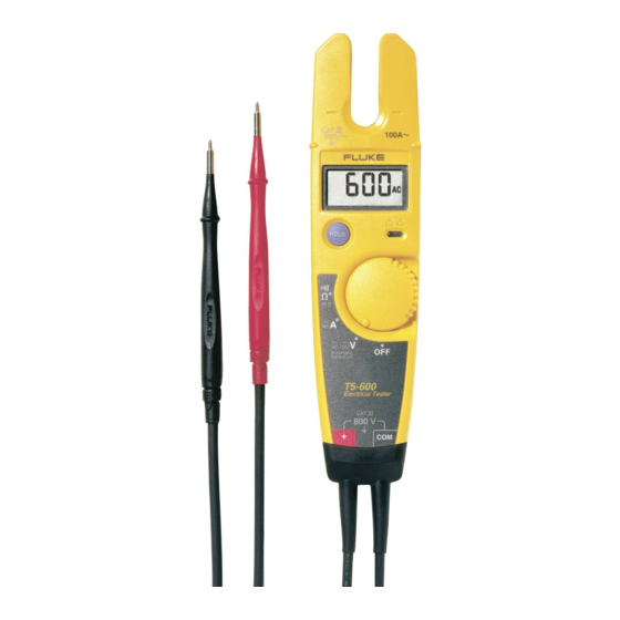
Fluke T5-600 / 5-1000 User Manual
- Service information (10 pages) ,
- Instruction sheet (6 pages) ,
- Instruction card (2 pages)
Advertisement
- 1 Read First: Safety Information
- 2 Voltage Indicator
- 3 Measuring Voltage (V)
- 4 Measuring Continuity and Resistance ( Ω )
- 5 Measuring AC Current (A)
- 6 Display Hold
- 7 Automatic Power Down
- 8 Low Battery Indicator
- 9 Maintenance
- 10 Battery Replacement
- 11 Replacement Parts
- 12 Accessories
- 13 Specifications
- 14 Limited Warranty & Limitation Of Liability
- 15 Videos
- 16 Documents / Resources
Read First: Safety Information

Use the tester only as specified in this Instruction Sheet, otherwise the protection provided by the tester may be impaired.

-
Do not use the tester if it is damaged or operating abnormally. Protection may be impaired.
-
Before each use:
Make sure the battery door is closed and latched.
Inspect the tester and test leads. Look for cracks, missing plastic, exposed metal, or damaged insulation. Replace damaged test leads before using the tester.
Verify the tester's operation by measuring a known voltage.
Perform the Battery Test to avoid false readings due to a low battery.
-
Replace the batteries as soon as the low battery indicator (
![]() ) appears.
) appears. -
Do not use the tester around explosive gas, vapor or dust.
-
Do not apply more than the rated voltage, as marked on the tester, between terminals or between any terminal and earth ground.
-
When servicing the tester, use only specified replacement parts.
-
Use caution when working above 30 V ac rms, 42 V ac peak, or 60 V dc.
-
When using the probes, keep your fingers behind the finger guards on the probes.
-
Connect the common test lead before you connect the live test lead. Disconnect the live test lead first.
 ) appears.
Symbols
 | AC (alternating current) |  | Earth ground |
 | DC (direct current) |  | Double insulated |
| Safety Information (Refer to the manual) |  | Battery |
Voltage Indicator

While the tester is on, the LED glows when more than 30 V ac or 60 V dc is present across the leads.
The LED can also glow at lower voltages. Be aware that such voltages pose a shock hazard.
Measuring Voltage (V)
The tester automatically selects dc (DC) or ac (AC) voltage mode based on the peak values of the measured signal.
The tester defaults to ac voltage when turned on.

DC Voltage
T5-600 maximum: 600 V
T5-1000 maximum: 1000 V
CAT III

AC Voltage
45 Hz to 66 Hz
T5-600 maximum: 600 V rms
T5-1000 maximum: 1000 V rms
CAT III
Measuring Continuity and Resistance ( Ω )
Continuity

Open

Short
Resistance

Beeper indicates shorts lasting 1 ms (1/1000 second) or longer.
Measuring AC Current (A)
")
- Range: 0 A to 100.0 A; 45 Hz to 66 Hz
- Remove probes from test points.
- Place conductor anywhere within the sensor zone (shaded area shown below).


Display Hold

To hold the reading on the display, press and release HOLD. The voltage indicator LED ( ) continues to operate.
To exit the display hold mode, press and release HOLD again, or turn the rotary switch to a new position.
Automatic Power Down
The tester turns off automatically if you do not turn the rotary switch or press HOLD for approximately 34 minutes. To resume operation, turn the tester off, wait two seconds, then turn the tester on.
Low Battery Indicator

To avoid false readings, which could lead to possible electric shock or personal injury, replace the battery as soon as the low battery indicator (  ) appears.
Maintenance
Clean the case with a damp cloth and detergent. Do not use abrasives or solvents.
Because the inputs are electronically protected, no fuses are required.
Battery Replacement
Observe the polarity markings inside the battery compartment.

Replacement Parts
| Test Lead Assembly. Replace only with Fluke double-insulated leads (  ) See "Accessories" for available probes. ) See "Accessories" for available probes. | PN 648029 |
| Battery Door | PN 648144 |
| Battery Door Screw | PN 643830 |
Accessories
H5 Belt Holster
TP1 Probe Set, Flat-Blade
TP4 Probe Set, 4 mm round
Service Information Sheet, PN 686953
To contact Fluke, call:
USA and Canada: 1-888-99-FLUKE (1-888-993-5853)
Europe: +31 402-678-200
Japan: +81-3-3434-0181
Singapore: +65-276- 6196
Anywhere in the world: +1-425-446-5500
Visit Fluke's Website at www.fluke.com.
Specifications
Calibration: One-year calibration cycle.
Maximum Voltage Between any Terminal and Earth Ground:
T5-600: 600 V rms, Overvoltage Category III;
T5-1000: 1000 V rms, Overvoltage Category III
Temperature: Operating: -10°C to +50°C (14°F to 122°F);
Storage: -30°C to +60°C (-22°F to +140°F)
Altitude: Operating: 2000 m (6562 ft); Storage: 10,000 m (32808 ft)
Relative Humidity: 0% to 95%, 5°C to 30°C (41°F to 86°F);
0% to 75%, 30°C to 40°C (86°F to 104°F);
0% to 45%, 40°C to 50°C (104°F to 122°F)
Battery Type and Life: AA (2); 400 hours continuous with alkaline; 200 hours continuous with zinc chloride
Shock, Vibration: 1 m drop at 15°C to 35°C (59°F to 95°F) per ANSI/ISA-S82.01-1994 and EN 61010-1: 1993. Sinusoidal vibration per MIL-PRF-28800F for a Class 2 instrument (5 Hz to 55 Hz, 3 g maximum).
Surge Protection: T5-600 6 kV per IEC 1010-1, 1990-09; T5-1000 8 kV per IEC 1010-1, 1990-09
Enclosure Rating: IP 52 per IEC 529, no vacuum applied
RF Field Specification: 0.5% full scale + (specified accuracy) at 3 V / m; Amps: >100 MHz, performance unspecified.
Safety: Complies with ANSI/ISA-S82.01-94 for use in Overvoltage category III (CAT III) locations, UL3111, CSA/CAN C22.2 No.1010.1-92, and EN61010-1: 1993.
EMC: EN 50081-1, EN 50082-1
Certifications:

Accuracy is specified for 1 year after calibration, at 18°C to 28°C (64°F to 82°F) with relative humidity to 90%. AC conversions are ac-coupled, average responding, and calibrated to the rms value of a sine wave input.
Accuracy specifications are given as follows:
±( [ % of reading] + [number of least significant digits] )
Temperature coefficient of 0.1 x (specified accuracy) / °C for <18°C or >28°C (< 64.4°F or > 82.4°F)
| Function | T5-600 Range | T5-1000 Range | Resolution | Accuracy |
 | 600 V rms | 1000 V rms | 1 V | ± (1.5% + 2 digits) |
 | 600 V | 1000 V | 1 V | ± (1% + 1 digit) |
 | 100.0 A | 100.0 A | 0.1 A | ± (3% + 3 digits) |
 | 1000 Ω | 1000 Ω | 1 Ω | ± (1% + 2 digits) |
⠀
| Function | Input Impedance (nominal) | Input Protection | |
| T5-600 | T5-1000 | ||
| 1 MΩ, <100 pF ac-coupled | 600 V rms | 1000 V rms |
| 1 MΩ, <100 pF | 600 V rms | 1000 V rms |
| >2.6 kΩ | 600 V rms | 1000 V rms |
⠀
| Function | Open Circuit Test Voltage | Short Circuit Current |
| 2.4 V dc (nominal) | <600 µA |
Limited Warranty & Limitation Of Liability
This Fluke product will be free from defects in material and workmanship for two years from the date of purchase. This warranty does not cover fuses, disposable batteries, or damage from accident, neglect, misuse or abnormal conditions of operation or handling.
Resellers are not authorized to extend any other warranty on Fluke's behalf. To obtain service during the warranty period, send the defective product to the nearest Fluke Authorized Service Center with a description of the problem.
THIS WARRANTY IS YOUR ONLY REMEDY. NO OTHER WARRANTIES, SUCH AS FITNESS FOR A PARTICULAR PURPOSE, ARE EXPRESSED OR IMPLIED. FLUKE IS NOT LIABLE FOR ANY SPECIAL, INDIRECT, INCIDENTAL OR CONSEQUENTIAL DAMAGES OR LOSSES, ARISING FROM ANY CAUSE OR THEORY.
Since some states or countries do not allow the exclusion or limitation of an implied warranty or of incidental or consequential damages, this limitation of liability may not apply to you.
Fluke Corporation
P.O. Box 9090
Everett WA 98206-9090
USA
Fluke Europe B.V.
PO Box 1186
5602 B.D. Eindhoven
The Netherlands

PN 688374 (English) July 1997, Rev. 1, 9/98
© 1997-1998 Fluke Corporation, All rights reserved. Printed in U.S.A.
All product names are trademarks of their respective companies.
VideosT5-600 Tutorial Video
Documents / Resources
References
Download manual
Here you can download full pdf version of manual, it may contain additional safety instructions, warranty information, FCC rules, etc.
Advertisement
Thank you! Your question has been received!


Need Assistance?
Do you have a question about the T5-600 that isn't answered in the manual? Leave your question here.