
Related Manuals for ADC PG-Flex FLC-704


Summary of Contents for ADC PG-Flex FLC-704
- Page 1 PG-F ECHNICAL RACTICE HANNEL POTS TART ROUND TART ENTRAL ERMINAL HANNEL Model List CLEI Code FLC-704 SCP-FLC704-042-03H ECTION...
- Page 2 Information furnished by ADC is believed to be accurate and reliable. In no event shall ADC be liable for any damages resulting from the loss of data, loss of use, or loss of profits and ADC further disclaims any and all liability for indirect, incidental, special, consequential or other similar damages.
- Page 3 • Unpack each container and visually inspect the contents for signs of damage. If the equipment has been damaged in transit, immediately report the extent of damage to the transportation company and to ADC. Order replacement equipment, if necessary. •...
- Page 4 Inspecting Your Shipment SCP-FLC704-042-03H January 6, 2003 FLC-704 List 4B...
-
Page 5: Table Of Contents
SCP-FLC704-042-03H ABLE OF ONTENTS Overview ____________________________________________________________________________ 1 Description ............................1 Front Panel ............................2 Specifications .............................3 Operational Capabilities........................4 Circuit Operation..........................4 Loop Start Operation ......................4 On-hook (Idle) Condition..................4 Subscriber Initiated Outgoing Call................5 Subscriber Receives Incoming Call ..............5 Busy Condition......................5 Ground Start Operation .......................6 Idle Condition......................6 Subscriber Initiates Outgoing Call ................6 Subscriber Receives Incoming Call ..............8... - Page 6 SCP-FLC704-042-03H January 6, 2003 FLC-704 List 4B...
- Page 7 SCP-FLC704-042-03H IST OF IGURES 1. FLC-704 Front Panel............................2 FLC-704 List 4B January 6, 2003...
- Page 8 SCP-FLC704-042-03H January 6, 2003 FLC-704 List 4B...
- Page 9 SCP-FLC704-042-03H IST OF ABLES 1. FLC-704 Front Panel LEDs and Labels ......................2 2. Circuit Interactions for an Idle Condition (Loop Start)..................4 3. Circuit Interactions When a Subscriber Initiates an Outgoing Call (Loop Start)..........5 4. Circuit Interactions When a Subscriber Receives an Incoming Call (Loop Start)..........5 5.
- Page 10 SCP-FLC704-042-03H January 6, 2003 FLC-704 List 4B...
-
Page 11: Overview
PG-Flex COT Shelf and the Central Office (CO) switch using A-Law pulse code modulation (PCM) encoding. In addition, the FLC-704 provides metallic access to the subscriber line connection through an optional metallic bypass pair for subscriber circuit testing. ESCRIPTION Features of the PG-Flex FLC-704 are: • eight LS/GS POTS subscriber interfaces •... -
Page 12: Front Panel
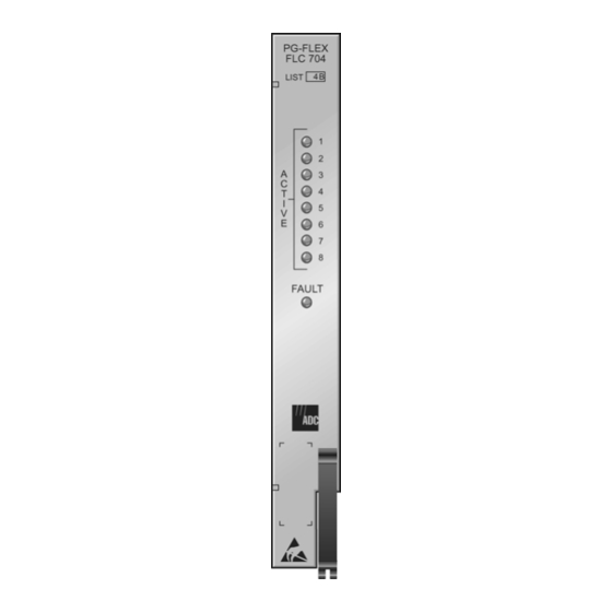
Front Panel SCP-FRC754-042-03H RONT ANEL The FLC-704 front panel (Figure 1) includes green status LEDs for each line indicating on-hook (idle), ringing, and off-hook conditions, as well as a red LED indicating a fault condition on the CU. Table 1 lists the different states and indications for the FLC-704 CU front panel LEDs. -
Page 13: Specifications
SCP-FRC754-042-03H Specifications PECIFICATIONS Electrical Characteristics 600 Ω Analog Impedance 100 Ω, (CO switch to COT) maximum Loop Resistance End-to-End Loss –2.5 dB ±1.0 dB at 100 Hz 500 Ω Ring-Ground Resistance Channel Signature Loop Start Lines Ground Start Lines Tip-Ring (open) 23.75 kΩ, 1% Tip-Ground... -
Page 14: Operational Capabilities
Operational Capabilities SCP-FRC754-042-03H PERATIONAL APABILITIES The FLC-704 List 1A CU provides eight loop start or ground start POTS interfaces to the CO switch. The unit performs the interface function between the analog POTS circuit and the internal digital pulse coded modulation (PCM) bus. -
Page 15: Subscriber Initiated Outgoing Call
SCP-FRC754-042-03H Circuit Operation Subscriber Initiated Outgoing Call The following occurs when the calling line goes off-hook (see Table 3 on page 5 for circuit interactions): • loop current flows and is detected by the FLC-704 CU • FLC-704 receives an off-hook signal from the RT •... -
Page 16: Ground Start Operation
Circuit Operation SCP-FRC754-042-03H Table 5. Circuit Interactions for a Busy Condition (Loop Start) FLC-704 FRC-754 Operation CO Switch Subscriber COCU RTCU ⇒ ⇒ Circuit busy No ringing No ringing ⇐ ⇐ Off-hook Off-hook Ground Start Operation The following section summarizes the ground start sequences for on-hook (idle), subscriber inititated outgoing calls, subscriber received incoming calls, and busy conditions. - Page 17 SCP-FRC754-042-03H Circuit Operation Table 7. Circuit Conditions When a Subscriber Initiates an Outgoing Call (Ground Start) FRC-754 Operation CO Switch FLC-704 COCU Subscriber RTCU ⇐ ⇐ Subscriber requests Ring - ground Ring - ground dialtone On-hook On-hook ⇒ ⇒ CO returns dialtone Tip - ground Tip - ground Dialtone...
-
Page 18: Subscriber Receives Incoming Call
Circuit Operation SCP-FRC754-042-03H Subscriber Receives Incoming Call The following occurs for an incoming call (see Table 8 for interactions): • FLC-704 detects a ringing signal from the CO, along with Tip-ground • FLC-704 signals the FRC-754 to connect Tip-ground and ringing to the PBX •... -
Page 19: Installation And Turn-Up
SCP-FRC754-042-03H Installing NSTALLATION AND NSTALLING Insert each FLC-704 CU into the COT Shelf and observe that all LEDs: • turn ON for approximately 2 seconds • scan from top to bottom • flash all ON, then OFF If the LEDs do not follow the above sequence, see Table Verify that the front panel indicators ACTIVE 1 through ACTIVE 8 and FAULT LEDs are all off when the PG-Flex system has powered up, established HDSL synchronized communications, and no calls are in... -
Page 20: Troubleshooting
4 Check the level at the COT coming from the CO switch. If it is correct, replace the COT CU. If it is not correct, refer the problem to the CO regarding the switch. 5 If the level is still not correct, re-insert the original COT CU. Contact ADC technical assistance per Product Support. -
Page 21: Product Support
ADC’s Return Material Authorization (RMA) Department. Call or write ADC’s RMA Department to ask for an RMA number and any additional instructions. Use the telephone number, fax number or email address listed below: •... - Page 22 If there is another reason for returning the equipment, please let us know so we can determine how best to help you. Pack the equipment in a shipping carton. Write ADC’s address and the RMA Number you received from the RMA Department clearly on the outside of the carton and return to: ADC DSL Systems, Inc.
-
Page 23: Fcc Classa Compliance
The FCC requires the user to be notified that any changes or modifications made to this device that are not expressly approved by ADC Technologies, Inc. voids the user's warranty. All wiring external to the product(s) should follow the provisions of the current edition of the National Electrical Code. -
Page 24: Acronyms
Modifications SCP-FRC754-042-03H CRONYMS 2B1Q 2 binary bits encoded in one quaternary symbol American Wire Gauge CLASS Custom Local Area Signaling Services Central Office Central Office Terminal Digital Signal Level Zero (64 kb/s) DTMF Dual Tone Multi Frequency HDSL High-bit-rate Digital Subscriber Line kbps KiloBits Per Second Mechanized Loop Testing... - Page 26 World Headquarters: ADC Telecommunications, Inc. 12501 Whitewater Drive Minnetonka, Minnesota USA 55343 For Technical Assistance: 800.366.3891 ´,Sl¶0ƨ 1251760...