Table of Contents
Advertisement
Advertisement
Table of Contents

Related Manuals for Jet JWS-35X Series


Summary of Contents for Jet JWS-35X Series
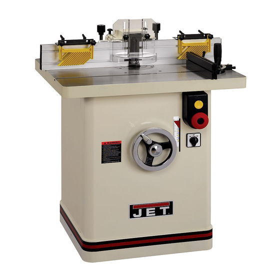
- Page 1 This Manual is Bookmarked Operating Instructions and Parts Manual Model JWS-35X Series Shaper Model: 2700 WMH TOOL GROUP, Inc. 2420 Vantage Drive Elgin, Illinois 60124 Part No. M-708323 Ph.: 800-274-6848 Revision B 03/08 www.wmhtoolgroup.com Copyright © 2008 WMH Tool Group, Inc.
-
Page 2: Warranty And Service
WMH Tool Group Authorized Service Centers can authorize warranty repair, assist you in obtaining parts, or perform routine maintenance and major repair on your JET® tools. For the name of an Authorized Service Center in your area call 1-800-274-6848. -
Page 3: Table Of Contents
Table of Contents Warranty and Service... 2 Table of Contents... 3 Warnings ... 4 Introduction ... 7 Specifications ... 7 Optional Accessories ... 7 Unpacking ... 7 Shipping Contents... 8 Assembly... 9 Cleaning ... 9 Lock Handle Assembly ... 9 Fence Assembly Installation... -
Page 4: Warnings
Warnings 1. Read and understand the entire owner's manual before attempting assembly or operation. 2. Read and understand the warnings posted on the machine and in this manual. Failure to comply with all of these warnings may cause serious injury. 3. - Page 5 21. Give your work undivided attention. Looking around, carrying on a conversation and “horse-play” are careless acts that can result in serious injury. 22. Maintain a balanced stance at all times so that you do not fall or lean against the blade or other moving parts.
- Page 6 Short stock – Never shape stock less than 12 inches in length without special fixtures. Where practical, shape longer stock and cut to size. 12 inch rule – When shaping, never allow your hands to come closer than 12 inches to the cutters.
-
Page 7: Introduction
This manual is provided by WMH Tool Group, Inc. covering the safe operation and maintenance procedures for a JET Model JWS-35X Series Shaper. This manual contains instructions on installation, safety precautions, general operating procedures, maintenance instructions and parts breakdown. This machine has been designed and constructed to provide years of trouble free operation if used in accordance with instructions set forth in this manual. -
Page 8: Shipping Contents
Shipping Contents Compare the contents of your container with the parts listings and illustrations on this page to make sure all parts are intact. Missing parts, if any, should be reported to your distributor. Read the instruction manual thoroughly for assembly, maintenance and safety instructions. -
Page 9: Assembly
Assembly Cleaning Referring to Figure 1: 1. Remove two hex cap screws and flat wash- ers (A) that secure the fence assembly (B) to the table and discard. 2. Set the fence assembly (B) aside to permit cleaning of the table. 3. -
Page 10: Cutter Guard
Cutter Guard Referring to Figure 2: Mount the cutter guard (A) to the safety guard holder (H). Insert two lock knobs (B) through the cutter guard slots and into the threaded mounting holes (J) on the safety guard holder (H). Feather Board Referring to Figure 2: Loosen lock handles (C) and slide the rail of the... -
Page 11: Adjustments
Figure 3 Adjustments When changing tools, making adjustments, or doing clean-up and maint- enance, always turn the machine off and unplug the machine from its power source. Fence Assembly Movement Referring to Figure 4: The adjustment controls of the fence assembly are as follows: A –... - Page 12 Coplanar Alignment Follow steps 1–5 to determine if alignment is necessary. Steps 6–9 will guide you through the alignment if required. Verifying that fences are coplanar 1. Remove the guard and spindle attachment. 2. Unlock knobs D and adjust the fence assembly (A) so it is positioned approximately at midpoint;...
-
Page 13: Ram Dial Calibration
in 1/16th increments or less at a time. Fence perpendicular to table The outfeed fence must also be perpendicular to the table. This can be checked as follows: 8. Place a square against the casting (L, Fig. 10) and table. 9. -
Page 14: Spindle Gib Adjustment
12mm wrench. Featherboard Hold-downs Referring to Figure 13: The JWS-35X Shaper comes equipped with two featherboard hold-downs (A, B) mounted on the infeed and outfeed fences. 1. Loosen lock handles (C) and lock knobs (D). -
Page 15: Spindle Assembly Installation
Spindle Assembly Installation Referring to Figure 14: The spindle assembly (B) is mounted to the arbor (H) and secured with a draw bar (O) and spindle nut (D). Use the following procedure to install the spindle assembly. Reverse the order to remove the spindle. -
Page 16: Shaper Cutter Installation
The arbor must be locked as described in Spindle Attachment Installation, step 2. 1. Remove the draw bar (O). 2. Loosen the spindle nut (D) then, using the spindle wrench (Inset A) continue to turn until the spindle breaks free of the arbor. Shaper Cutter Installation Note: Spindle installation is described in the previous section. -
Page 17: Changing Spindle Speed
Changing Spindle Speed The JWS-35X Shaper is equipped with pulleys that allow you to change the spindle speed. The belt placed on the upper pulleys as shown in position B (Fig. -
Page 18: Precision Miter Gauge
4. Work the drive belt down all the way past the pulleys. 5. Continue sliding the belt down on the left side until it is free of the bottom pulley (E), then remove the belt over the top of the motor pulley (B). - Page 19 3. Measure the accuracy of the gauge against the slot with a combination square. If adjustment is necessary: 4. Adjust the body (B) until it is perfectly square (90º) to the miter slot (H).
-
Page 20: Operating Controls
2. Press the green button to restart the machine. Figure 18 Safety Key The start/stop switch on the JWS-35X Shaper comes equipped with a magnetic safety key. When in place on the switch as shown in Figure 18 the magnetic safety key trips a relay which will allow the machine to start and stop when the respective switches are pressed. -
Page 21: Operations
Operations Overview Before applying power to the machine, Check the motor and switch wiring diagrams for proper voltage connections. Check that all mounting screws and bolts are tight. Turn on the motor momentarily to check for proper rotation. The spindle should rotate counterclock- wise when looking down on the spindle. - Page 22 Using the Fence Using the fence is the safest and most satisfactory method of shaping, and should always be used when the work permits. Almost all straight work can be used with the fence. For average work, where a portion of the original edge of the work is not to be touched by the cutter, both the front and rear fences are set in a straight line as shown in Figure 22.
- Page 23 "Z" Dimension Before making a template (or using the edge of the workpiece) for shaper cutting, the "Z" dimension must be established in order to determine the shape and size of the finished stock. The "Z" dimension is the difference between the innermost part of the cutter edge and the outside diameter of the ball bearing follower (collar).
- Page 24 Edge Shaping When edge shaping, never attempt to hand guide any stock less than 12 inches long, or narrower than 3 inches without the use of a special guide as shown in Figure 27. When edge shaping, the work- piece must be at least 12 inches long unless a special guide is used.
- Page 25 Straight Line Bevel Shaping To shape a beveled straight edge, use a bevel- edge shaping jig in combination with the regular fence as shown in Figure 31. Figure 31 To perform a bevel-edge cut, the in-feed edge of the jig is placed against the infeed fence and clamped to the table as shown in Figure 32.
- Page 26 If the workpiece is to be shaped all around the perimeter, hold it firmly and push the work straight into the cutter until the depth of cut is established by the collar as shown in Figure 36. Continue to feed the work so that the point of contact on the edge is always 90 degrees to the collar (or directly in line with the cutter edge) and held firmly against When the workpiece is not contoured all around,...
- Page 27 3. Using the collar between the two cutters has the advantages and disadvantages of the first two procedures, and is frequently used where both edges of the work are to be molded, Figure 41. Note: It is advisable to place the cutter as low as possible on the spindle to reduce spindle deflection and ensure the best possible finish.
- Page 28 Arcs and Circles Large circular and arc-shaped stock can be shaped as described in Contour Edge Shaping on page 24. However, smaller sized stock requires the use of special shaping jigs similar to those shown in Figure 44. With the entire fence assembly removed, carefully position the jig for desired depth-of-cut and securely clamp to the table.
- Page 29 Templates The template must be thick enough to provide a solid bearing edge against a collar. When constructing a template similar to the one shown in Figure 46, keep in mind that it serves only as a guide for the cutter. If the workpiece requires all-around shaping, the template can be constructed from several sections pieced together as shown in Figure 47.
-
Page 30: Special Cuts
Special Cuts The illustrations in this section show the profile, or section, views made by the cutter(s). The most efficient cutters are carbide tipped to ensure clean and long-term cutting. Small cutters may be solid carbide, and some use inserts. Since there are such a wide variety of choices, the operator is limited only by his experience and imagination. - Page 31 Figure 55 shows BOTH cuts required for a window sash rail end. The first operation at top is a rabbet cut made with a groove cutter. The second operation is performed with a stub spindle and buttonhead screw. Butt Joints All butt-type joints require both work-pieces to be perfectly square and straight-edged.
- Page 32 Tenoning The tenoning fixture illustrated in Figure 60 shows a miter gauge equipped with a hold-down for shaping the ends of narrow work-pieces. The miter gauge can also be adapted to cut square and centered tenons at the ends of legs for tables, chairs, etc.
-
Page 33: Troubleshooting
Troubleshooting Trouble 1. Cord unplugged from the power Shaper will not start. source. 2. Fuse blown or circuited breaker tripped. 3. Cord damaged. 4. Reversing switch is in the Off position. 5. Overload tripped. 6. Cabinet door is open. 1. Extension cord or wiring Overload kicks out inadequate size. -
Page 34: Parts
Troubleshooting Trouble 1. Characteristic of this type of cut. Edge splits off on cross grain cut. 1. Variation of pressure holding work Raised areas on against cutter. shaped edge. 1. Feeding in wrong direction. Work pulled from hand. 1. Fence misalignment. Depth of cut not uniform. - Page 35 Table – Parts List Index No. Part No. Description Size 1 ...TS-1521011 ...Socket Set Screw... M4x4 ... 3 2 ...JWS35X-102...Insert Ring (Small) ..1 3 ...TS-2285121 ...Flat Head Machine Screw... M5x12 ... 3 4 ...JWS35X-104...Insert Ring (Large) ..1 5 ...JWS35X-105...Table ...
- Page 36 Table – Assembly Drawing...
- Page 37 Fence – Parts List Index No. Part No. Description Size 1 ...JWS35X-201...Knob..4 2 ...PM2700-237 ...Feather Board ..2 3 ...PM2700-234 ...Bracket ..2 4 ...TS-1550061 ...Flat Washer... M8 ... 4 5 ...PM2700-232 ...Lock Handle ..4 6 ...PM2700-235 ...Carriage Bolt ...
- Page 38 Fence – Assembly Drawing...
- Page 39 Frame and Motor – Parts List Index No. Part No. Description Size 1 ...PM2700-305A ...Spindle Nut... M40x2.5p ... 1 2 ...PM2700-306 ...Retaining Ring ... STW-40... 1 3 ...TS-2246202 ...Button Head Socket Screw ... M6x20 ... 8 4 ...TS-2361061 ...Lock Washer ... M6 ... 8 5 ...PM2700-308 ...Shaft Top Bearing Cover ...
- Page 40 Frame and Motor – Parts List Index No. Part No. Description 56 ...JWS35X-356...Cover..1 57 ...JWS35X-357...Motor Pulley ..1 58 ...JWS35X-358...Motor ... 3HP, 230V, 1Ph ... 1 ...JWS35X-358A ...Motor ... 5HP, 230V, 1Ph ... 1 ...JWS35X-358B ...Motor ... 5HP, 230/460V, 3Ph ... 1 ...JWS35X-358CS...Centrifugal Switch (not shown) ...
- Page 41 ...PM2700-448A ...Forward/Reverse Switch ... 5HP/1Ph ... 1 ...PM2700-448B ...Forward/Reverse Switch ... 5HP/3Ph ... 1 11 ...JWS35X-411...Stripe..1 12 ...JWS35X-412...JET Logo..1 13 ...PM2700-416 ...Bumper..2 14 ...JWS35X-414...Cabinet..1 15 ...TS-1540041 ...Hex Nut ... M6 ... 4 16 ...TS-2361061 ...Lock Washer ...
- Page 42 Cabinet and Base – Assembly Drawing...
- Page 43 Elevator – Parts and Assembly Index No. Part No. Description Size 1 ...JWS35X-501...Lead Screw ..1 2 ...JWS35X-502...Key ... 5x5x12 ... 2 3 ...PM2700-342 ...Retaining Ring ... STW-15... 1 4 ...PM2700-503 ...Thrust Bearing ... 51202 ... 2 5 ...PM2700-504 ...Hex Nut ... M20-1.5P ... 4 6 ...PM2700-505 ...Adjusting Bolt ...
- Page 44 Spindle Assembly – Parts Index No. Part No. 1 ...TS-1505031 ...Socket Head Cap Screw... M10x25 ... 4 2 ...PM2700-708 ...Special Washer..1 3 ...PM2700-709 ...Keyed Collar..1 4 ...PM2700-710 ...Collar... I.D. 3/4” x 1/2”T... 4 5 ...PM2700-711 ...Collar... I.D. 3/4” x 3/4”T... 2 6 ...PM2700-712 ...Spindle ...
- Page 45 Spindle Assembly Drawing...
-
Page 46: Wiring Diagrams
Wiring Diagrams 3HP/5HP, 230V, 1Phase White Yellow Black White Black Yellow Yellow Black Yellow White Black BLACK WHITE WHITE Black Green White Black... - Page 47 5HP, 230V-460V, 3Phase 5HP,230/460 V,3PH Magnetic Switch Green Black White Green Yellow WHITE YELLOW YELLOW BLACK Motor Yellow Black Green Green W 14 Green L1L2L3 Yellow White Black Electrical Board...
- Page 48 Notes...
- Page 49 WMH Tool Group, Inc. 2420 Vantage Drive Elgin, Illinois 60124 Phone: 800-274-6848 www.wmhtoolgroup.com...