Table of Contents
Advertisement
Quick Links
Advertisement
Table of Contents

Related Manuals for Pall Allegro


Summary of Contents for Pall Allegro
- Page 1 Instructions For Use USD 2743 Allegro™ 200 L Single-Use Mixer...
-
Page 2: Table Of Contents
5. System Installation and Operation ..................6 Connections to the User Control Interface (UCI) ..............6 Safety Interlocks (micro-switches) Check .................7 Allegro Mixer Tote & Single-use System – Pre Installation Checks ...........9 System Installation .........................10 Mixer Bag Inflation .........................15 Adding Fluid and Solids to the Single-use Mixer System............17 Operating the Mixer .......................19... -
Page 3: Introduction
Allegro single-use systems are typically sterilized by gamma irradiation. 1. Store the Allegro 3D system in clean, dry conditions between 4 and 40 °C without exposure to radiation sources like direct sunlight and, wherever practical, in the packaging as delivered. -
Page 4: System Pictures And Schematics
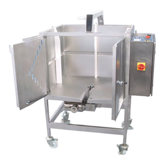
4. System Pictures and Schematics Figure 1 Allegro single-use mixer tote (with mixer biocontainer) Mixer Tote Support Arm Mixer Biocontainer User Control Interface (UCI) Full Access Doors Motor & Gear Figure 2 Allegro single-use mixer biocontainer Impeller Cover & Powder Port... - Page 5 Figure 3 Allegro mixer tote (open ready to accept single-use system) Figure 4 Allegro mixer tote with mixer system installed USD 2743 www.pall.com/biopharm...
-
Page 6: System Installation And Operation
5. System Installation and Operation Connections to the User Control Interface (UCI) 1. Connect the power cord to the power outlet according to the specified voltage and current of your unit (power as per specification table, see section 8). Caution: Ensure the power cable is not positioned underneath the tote to avoid potential fluid contact. -
Page 7: Safety Interlocks (Micro-Switches) Check
Depressing the ‘SHAFT’ micro switch to confirm it is working prior to system installation 4. Close the doors to the tote and rotate the handle clockwise fully so that it is in the secured (closed) position (vertical) as shown in Figure 9 below. USD 2743 www.pall.com/biopharm... - Page 8 7. Check that the appropriate LED (labelled ‘SUPPORT’) on the UCI is green (Figure 10). If the ‘SUPPORT’ LED is not illuminated green at this stage, refer to ‘Troubleshooting’, section 7. Assuming correct operation of all safety micro switches, the system is now ready for installation of the Allegro single-use mixer system. USD 2743...
-
Page 9: Allegro Mixer Tote & Single-Use System - Pre Installation Checks
Allegro Mixer system from its packaging (retaining any appropriate labels as necessary). 2. Take care not to snag any parts of the tubing assemblies or additional system components when removing the system (ensure the packaging is fully open to allow easy removal of the system). -
Page 10: System Installation
System Installation 1. Install Allegro single-use system into the mixer tote. A. Holding the system securely as shown below (Figure 12) align the shaft on the single- use system, with the tube support in the centre of the mixer tote and the inlet port plate to the right hands side of the impeller cover. - Page 11 2. Check that the appropriate LED (labelled ‘SHAFT’) on the UCI is illuminated green as shown in Figure 14 below. If the ‘SHAFT’ LED is not illuminated green at this stage, please refer to ‘Troubleshooting’ (Section 7). Figure 14 ‘SHAFT’ interlock illuminated indicating correct location of shaft USD 2743 www.pall.com/biopharm...
- Page 12 3. Before closing the doors attach the inflation and exhaust tubing to the UCI and secure with cable ties. The ¼ inch line (Gas Inlet on Figure 2) connects to the ‘IN’ hosebarb on the UCI and the ½ inch tubing (Gas Return on Figure 2) connects to the ‘OUT’ line on the UCI as shown in Figure 15 below.
- Page 13 (Figure 19). Figure 19 Closing the doors ensuring the system locating plate remains under the doors System Locating Plate USD 2743 www.pall.com/biopharm...
- Page 14 7. Turn the handle to the ‘closed’ (vertical position, Figure 20) to secure, check that the appropriate LED on the UCI (labelled ‘DOOR) is illuminated (Figure 21). If the ‘Door’ LED is not illuminated green at this stage, please refer to the Troubleshooting Table (Section 7). Figure 20 Handle to ‘closed’...
-
Page 15: Mixer Bag Inflation
4 – 10 mbar. 4. Secure the support arm of the mixer tote to the powder port of the single-use mixer system (Figure 24). Figure 24 Powder port support arm in correct location Powder Port Support Arm USD 2743 www.pall.com/biopharm... - Page 16 5. Once installed, check that the appropriate LED on the UCI (labelled ‘SUPPORT’) is illuminated, indicating that the powder port is correctly supported by the mixer hardware. If the LED is not illuminated green at this stage, please refer to the Troubleshooting table under section 7.
-
Page 17: Adding Fluid And Solids To The Single-Use Mixer System
When adding bulk fluid monitor the pressure on the bag inflation gauge (Figure 27) to make sure it does not increase above 20 mbar. If it does increase above 20 mbar, reduce the fluid filling rate into the system. USD 2743 www.pall.com/biopharm... - Page 18 Figure 27 UCI showing higher pressure (10 – 20 mbar) during fluid filling due to the pressure caused by fluid addition. Do not allow this to increase above 20 mbar. 3. Stop filling when the desired volume in the mixer biocontainer is achieved. Solids Addition: A.
-
Page 19: Operating The Mixer
Note: Maximum life (continuous mixing) is 3 days (72 hours). Figure 29 Setting the impeller speed (rpm) for the mixer AUTO To set the rpm/speed for the rotation, use the panel to increase the rpm figure to the desired value. STOP USD 2743 www.pall.com/biopharm... - Page 20 Figure 30 Changing the direction of rotation of the impeller The direction of rotation is set as either ‘FWD’ or ‘REV’. AUTO FWD = Counter-clockwise/Downflow REV = Clockwise/Up-flow To change from current direction: 1. Press Either FWD or REV will flash for approx 4 seconds, indicating the new direction 2.
-
Page 21: Drain/Removal Instructions
100 L to avoid air entrapment. Gas blanket should be switched off as the last of the fluid exists the mixer biocontainer. Mixer biocontainer will not collapse during draining/dispensing, thus appropriate venting will be required prior to system removal. USD 2743 www.pall.com/biopharm... - Page 22 Note 1: The tote design maximizes fluid recovery, which can be further improved by lifting the edges of the biocontainer in the last few minutes of the dispensing stage. Typical residual volume following draining is typically less than 150 mL. Note 2: If gas blanket is used during draining, this must be deactivated at the end of dispensing.
-
Page 23: Troubleshooting
GREEN. ‘Shaft’ LED does illuminate. If the switch is not working please call Pall. If the switch is working, proceed to next ‘possible cause’. Misalignment of Re-install the single-use system, taking care to align the seal housing. -
Page 24: Specification Tables
8. Specification Tables Mixer Tote Part Number LGRMXTTE200L230 Voltage 230 Vac Current 5.1 A Frequency 50 Hz Volume 50 – 200 L Gas Supply 4 – 6 barg Gas Connection 10 mm Pneumatic tubing outside diameter Weight 120 Kg (without fluid in system) Footprint 1054 mm (W) x 748 mm (D) Height... -
Page 25: General Maintenance Recommendations
50 – 200 9. General Maintenance Recommendations It is recommended that the Allegro 200 L single-use mixer be serviced on an annual basis. Pall Advanced Separation Systems (PASS) servicing group can provide this as a service. Please contact your Pall representative for further details. -
Page 26: Weee Compliance. Reuse, Recycling And Recovery (2002/96/Ec)
Pall liability under any warrantee is limited solely to replacing, or issuing credit for the Allegro systems and hardware that may become defective during the Warrantee Period. -
Page 27: Ce Declaration
CE Declaration USD 2743 www.pall.com/biopharm... - Page 28 United States International Offices 1.800.717.7255 toll free (USA) Pall Corporation has offices and plants throughout the world in locations such as: Argentina, Australia, Austria, Belgium, Brazil, Canada, China, France, Germany, India, 1.516.484.5400 phone Indonesia, Ireland, Italy, Japan, Korea, Malaysia, Mexico, the Netherlands, New Zealand, 1.516.801.9548 fax...