Table of Contents
Advertisement
Quick Links
Advertisement
Table of Contents

Related Manuals for York YCAV1039


Summary of Contents for York YCAV1039
- Page 1 AIR-COOLED SCREW LIQUID CHILLERS INSTALLATION, OPERATION, MAINTENANCE Supersedes 201.21-NM4 (616) Form 201.21-NM4 (1020) 035-20995-000 MODELS YCAV1039-1909, 50 HZ STYLE A (960-1815KW) E/V HIGH EFFICIENCY AND S/P STANDARD EFFICIENCY AIR-COOLED SCREW LIQUID CHILLERS R-134a Issue Date: October 2, 2020...
- Page 2 FORM 201.21-NM4 (1020) IMPORTANT! READ BEFORE PROCEEDING! GENERAL SAFETY GUIDELINES This equipment is a relatively complicated apparatus. which it is situated, as well as severe personal injury or During rigging, installation, operation, maintenance, death to themselves and people at the site. or service, individuals may be exposed to certain com- This document is intended for use by owner-authorized ponents or conditions including, but not limited to:...
- Page 3 Planned Service Agreement that leverages real time and generalized conditions. In lieu of the traditional and historical data, delivering performance reporting, maintenance program, a Johnson Controls YORK corrective actions required and data enabled guidance Conditioned Based Maintenance (CBM) program can for optimal operation and lifecycle assurance.
-
Page 4: Table Of Contents
FORM 201.21-NM4 (1020) TABLE OF CONTENTS SECTION 1 - GENERAL CHILLER INFORMATION & SAFETY VIBRATION ISOLATION ........20 UNIT NOMENCLATURE ........21 INTRODUCTION .............9 PRODUCT IDENTIFICATION NUMBER ..22 WARRANTY .............9 SAFETY ..............9 SECTION 3 -RIGGING, HANDLING AND Standards for Safety..........9 STORAGE RESPONSIBILITY FOR SAFETY .......10 ABOUT THIS MANUAL ........10 DELIVERY AND STORAGE ........26 MISUSE OF EQUIPMENT ........10... - Page 5 FORM 201.21-NM4 (1020) TABLE OF CONTENTS (CONT’D) SECTION 5 - COMMISSIONING PREPARATION ............36 WEIGHT DISTRIBUTION & PREPARATION - GENERAL .......36 ISOLATOR MOUNTING ....... 117 Inspection..............36 ISOLATOR MOUNTING POSITIONS....118 Refrigerant Charge ..........36 SEISMIC ISOLATOR INSTALLATION ...123 Service and Oil Line Valves .........36 NEOPRENE ISOLATOR POSITION ....124 Compressor Oil .............36 1"...
- Page 6 FORM 201.21-NM4 (1020) TABLE OF CONTENTS (CONT’D) SECTION 7 - OPERATION VSD DATA KEY ...........230 OPERATING CONTROLS ........166 OPERATING HOURS & START KEYS ....232 BASIC OPERATING SEQUENCE .....168 HISTORY KEY .............233 NUMBER OF COMPRESSORS TO START ..169 Unit Data.............234 General..............169 VSD Data ............235 Standard IPLV.............169 System Data ............236...
- Page 7 Table 6 - Current Load Limiting/Unloading ...178 Table 24 - Digital Output Connections ....278 Table 7 - Discharge Pressure Load Limiting/ Table 25 - Mustang Chiller YORK Talk Unloading ..........178 Control Data ...........280 Table 8 - Suction Pressure Load Limiting/ Table 26 - DXST/ISN Transmitted Data ....281...
- Page 8 FORM 201.21-NM4 (1020) LIST OF FIGURES Fig 19 - VSD Logic Board ........133 Fig 1 - PWM Current Waveform ......18 Fig 20 - VSD Logic Board ........134 Fig 2 - PWM Voltage Waveform.......18 Fig 21 - Power Components ........135 Fig 3 - Pipework Arrangement ........32 Fig 22 - Power Components ........136 Fig 4 - Victaulic Groove..........32 Fig 23 - Fan Contactors ...........137...
-
Page 9: Section 1 - General Chiller Information & Safety
The most appropriate rigging and lifting method will depend on job specific factors, such as the • Only genuine YORK approved spare parts, oils, rigging equipment available and site needs. Therefore, coolants, and refrigerants must be used. Recom-... -
Page 10: Responsibility For Safety
This manual and any other document supplied with the any machinery is primarily responsible for: unit are the property of YORK which reserves all rights. They may not be reproduced, in whole or in part, without •... -
Page 11: Pressure Systems
FORM 201.21-NM4 (1020) Pressure Systems Sharp Edges The unit contains refrigerant vapor and liquid under The fins on the air-cooled condenser coils have sharp pressure, release of which can be a danger and cause metal edges. Reasonable care should be taken when injury. -
Page 12: Section 2 - Product Description
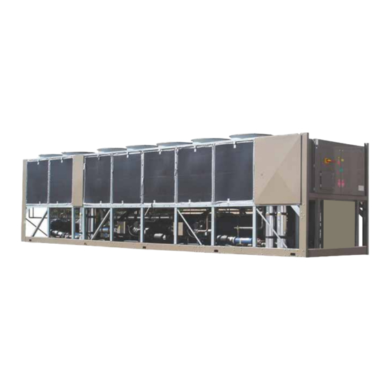
50074d INTRODUCTION General System Description YORK YCAV R134a chillers are designed for water The Latitude (YCAV) Air Cooled Chiller line combines or glycol cooling. All units are designed to be located the best of modern screw compressor design with the outside on the roof of a building or at ground level. -
Page 13: Compressor
FORM 201.21-NM4 (1020) An integral liquid cooled, transistorized, PWM, Variable Refrigerant gas is injected into the void created by the Speed Drive (VSD) is controlled by the chiller micro- un-meshing of the five lobed male and seven lobed fe- processor control panel to start/stop, select compressors male rotor. -
Page 14: Evaporator
PRODUCT DESCRIPTION FORM 201.21-NM4 (1020) Motor cooling is provided by suction gas from the The water nozzles are provided with grooves for evaporator flowing across the motor. Redundant over- mechanical couplings and should be insulated by the load protection is provided using both internal thermistor contractor after pipe installation. -
Page 15: Condensor
1.7X suction when the economizer solenoid is activated. The oil (YORK “L” oil – a POE oil used for all refriger- The liquid in the tank is fed to the evaporator. -
Page 16: Oil Cooling
PRODUCT DESCRIPTION FORM 201.21-NM4 (1020) Oil Cooling Each Power Compartment Contains Oil cooling is provided by routing oil from the oil sepa- Incoming single point power is standard utilizing either rator through several of the top rows of the condenser a lockable circuit breaker or terminal block, 115VAC coils and back to the compressor. -
Page 17: Display
FORM 201.21-NM4 (1020) Display Keypad An operator keypad allows complete control of the The display consists of a liquid crystal 2 line by 40 system from a central location. The keypad utilizes characters per line display, with backlighting for outdoor an overlay to allow use in 5 languages. -
Page 18: Variable Speed Drive (Vsd)
PRODUCT DESCRIPTION FORM 201.21-NM4 (1020) The power section of the drive is composed of four Variable Speed Drive (VSD) major blocks consisting of an AC to DC rectifier section with accompanying pre-charge circuit, a DC link filter The VSD (variable speed drive) is a liquid cooled, transistorized, PWM inverter, which provides speed section, a three phase DC to AC inverter section, and an output suppression network. -
Page 19: Accessories & Options
FORM 201.21-NM4 (1020) Gate Bipolar Transistor (IGBT) modules mounted to a ing high voltage to the VSD Logic Board. A Current liquid cooled heatsink, and a IGBT Gate Driver Board, Transformer is included on each output phase assembly which provides the On and Off gating pulses to the to provide motor current information to the VSD logic IGBT’s as determined by the VSD Logic board. -
Page 20: Dx Cooler Options
PRODUCT DESCRIPTION FORM 201.21-NM4 (1020) Louvered Panels (Full Unit) enclosure – Louvered DX COOLER OPTIONS panels over condenser coils and around the bottom of the unit (Factory- or field-mounted). 300 PSIG (21 bar) Waterside Design Working Pressure – The DX cooler waterside is designed and constructed for 300 PSIG (21 bar) working pressure. -
Page 21: Unit Nomenclature
UNIT MODEL NUMBER NOMENCLATURE NOMENCLATURE The model number denotes the following characteristics of the unit. YC A V - 1039 - S - A - 50 VOLTAGE CODE YORK CHILLER 50 = 380/415-3-50 AIR COOLED REFRIGERANT A = R134 V = VARIABLE SPEED... -
Page 22: Product Identification Number
PRODUCT DESCRIPTION FORM 201.21-NM4 (1020) COMPLETE PIN NUMBER DESCRIPTION Feature Description Option Description CONTRACT Contract Number Contract Number = {num} ORDER Order Quantity Order quantity = {ord_qty} USA origin not required USA Origin USA origin required Crane/Rigging Shipping Weight = {lbs} SHIP WT Shipping Weight Crane/Rigging Shipping Weight = {kg}... - Page 23 FORM 201.21-NM4 (1020) COMPLETE PIN NUMBER DESCRIPTION (CON'T) TRANS Control Transformer (PIN 18) Control Transformer required Special Transformer or Power Strip required No Option Required Convenience Outlet, 115V GFI Convenience Outlet (PIN 19) (Customer Powered) Special quote PIN 20 No option required Special quote No BAS Reset/Offset required BAS/EMS Temp Reset/Offset...
- Page 24 PRODUCT DESCRIPTION FORM 201.21-NM4 (1020) COMPLETE PIN NUMBER DESCRIPTION (CON'T) Standard Valves required VALVES Valves (PIN 32) Special Optional Valves required No option required HGBP PIN 33 Special quote No option required GAUGE PIN 34 Special quote No option required OVERLOAD PIN 35 Special quote...
- Page 25 FORM 201.21-NM4 (1020) COMPLETE PIN NUMBER DESCRIPTION (CON'T) Louvered (full unit) Encl Panels (factory) PANEL - Con't Enclosure Panels (PIN 48) Louvered (full unit) Encl Panels (field) Special Enclosure Panels required No Sound Enclosure required Perimeter Sound Package Acoustic Sound Blanket ACOUSTIC Acoustical arrgt (PIN 49) Acoustic Sound Blanket &...
-
Page 26: Section 3 -Rigging, Handling And Storage
HANDLING AND STORAGE FORM 201.21-NM4 (1020) RIGGING, HANDLING AND STORAGE LD19197 Rigging and lifting should only be done by a professional rigger in accordance with a written rig- ging and lifting plan. The most appropriate rigging and lifting method will depend on job specific factors, such as the rigging equipment available and site needs. -
Page 27: Moving The Chiller
FORM 201.21-NM4 (1020) MOVING THE CHILLER LIFTING USING LUGS Prior to moving the unit, ensure that the installation Units are provided with lifting holes in the base frame site is suitable for installing the unit and is easily ca- which accept the accessory lifting lug set as shown in pable of supporting the weight of the unit and all as- the figure below. -
Page 28: Unit Rigging
INSTALLATION FORM 201.21-NM4 (1020) UNIT RIGGING NOTE: Unit must be lifted level to prevent damage to the structual integrity of the unit NOTE: Weights and approximate center of gravity lo- cation shown for base unit. Any options selected may add weight to the unit and affect the center of gravity. Locate the center of gravity through trial lifts to account for possible variations in unit configuration. -
Page 29: Section 4 - Installation
FORM 201.21-NM4 (1020) INSTALLATION LOCATION REQUIREMENTS Any ductwork or attenuators fitted to the unit must not have a total static pressure resistance, at full unit To achieve optimum performance and trouble-free airflow, exceeding the capability of the fans installed service, it is essential that the proposed installation site in the unit. -
Page 30: Location Clearances
INSTALLATION FORM 201.21-NM4 (1020) LOCATION CLEARANCES Installation Adequate clearances around the unit(s) are required for Place each mount in its correct position and lower the the unrestricted airflow for the air-cooled condenser coils unit carefully onto the mounts ensuring the mount en- and to prevent re-circulation of warm discharge air back gages in the mounting holes in the unit base frame. - Page 31 150 PSIG (10 bar) working pressure and hav- circulated when the ambient temperature approaches ing a 1” N.P.T. connection can be obtained from YORK freezing point. as an accessory for the unit. Alternatively, a differential...
-
Page 32: Water Treatment
Victaulic Groove type (see FIG. 4). Aerated, brackish or salt water is not recommended for use in the water system(s). YORK recommends that a water treatment specialist should be consulted to determine whether the proposed water composition will adversely affect the evaporator materials of carbon steel and copper. -
Page 33: Refrigerant Relief Valve Piping
FORM 201.21-NM4 (1020) When ducting is to be fitted to the fan discharge it is REFRIGERANT RELIEF VALVE PIPING recommended that the duct should be the same cross- The evaporator is protected against internal refrigerant sectional area as the fan outlet and straight for at least overpressure by refrigerant relief valves. -
Page 34: Power Wiring
In (not supplied by YORK). cold weather, this could cause serious damage to the chiller due to evaporator freeze-up. Do not remove power unless... -
Page 35: Volts Free Contacts
FORM 201.21-NM4 (1020) 136). If remote start/stop is not utilized, a jumper must VOLTS FREE CONTACTS be paced across the terminals to allow the system to run. The remote run/stop circuitry is a 115VAC circuit. Voltage free contacts are rated at 115VAC, 100VA re- sistive load only. -
Page 36: Section 5 - Commissioning
To add oil to a circuit - connect a YORK hand oil pump (Part No. 470-10654-000) to the 1/4” oil charging valve Perform the commissioning using the detailed checks... -
Page 37: Power Connections
FORM 201.21-NM4 (1020) Power Connections sensor well in the evaporator. This sensor is part of the pump control freeze protection operation. It provides Check that the customer power cables are connected cor- some freeze protection and must always be fully in- rectly to the terminal blocks or optional circuit breaker. -
Page 38: Interlocks
COMMISSIONING FORM 201.21-NM4 (1020) Interlocks on the chilled liquid temperature and rate of temperature change. If a high heat load is present, the controller will Verify that liquid is flowing through the cooler and that increase the speed of the compressor(s). heat load is present. -
Page 39: Condensor & Fan Rotation
FORM 201.21-NM4 (1020) General Operation After completion of the above checks for System 1, switch OFF the ‘SYS 1’ switch on the keypad and repeat the process for each subsequent system. When all run correctly, stop the unit, switch all applicable switches to the ‘ON’... -
Page 40: Section 6 - Technical Data
TECHNICAL DATA FORM 201.21-NM4 (1020) WATER PRESSURE DROP (SI) Pressure Drop Through 3 and 4 Circuit YCAV Evaporators 1000 10.0 100.0 Water Flow Rate (l/s) COOLER YCAV MODELS 1039EA/VA 1039SA/PA 0969EA/VA 1429SA/PA 1309EA/VA 1309SA/PA 1169EA/VA 1139SA/PA 1649SA/PA 1549SA/PA 1429EA/VA 1909SA/PA 1829SA/PA 1739SA/PA 1739EA/VA... -
Page 41: Glycol Correction Factors
FORM 201.21-NM4 (1020) GLYCOL CORRECTION FACTORS GLYCOL CORRECTION FACTORS The cooler is designed in accordance with ARI- 590-92 which allows for an increase in pressure ETHYLENE GLYCOL 1.45 drop of up to 15% above the design value shown 1.40 on page 40. Debris in the water may also cause 1.35 additional pressure drop. -
Page 42: Water Temp. And Flows
-17.7 51.7 NOTES: 1. For leaving brine temperature below 40°F (4.4°C), contact your nearest YORK office for application requirements. 2. For leaving water temperature higher than 60°F (15.6°C), contact the nearest YORK office for application guidelines. JOHNSON CONTROLS JOHNSON CONTROLS... - Page 43 FORM 201.21-NM4 (1020) This page intentionally left blank. JOHNSON CONTROLS JOHNSON CONTROLS...
-
Page 44: Physical Data
TECHNICAL DATA FORM 201.21-NM4 (1020) PHYSICAL DATA (SI Standard Efficiency) STANDARD EFFICIENCY Refrigerant R-134a MODEL NUMBER (YCAV____ S/P) YCAV1039 YCAV1139 YCAV1309 YCAV1429 YCAV1549 YCAV1649 YCAV1739 YCAV1829 YCAV1909 General Unit Data Number of Independent Refrigerant Circuits 105 / 105 / 84/ 84/ 84... - Page 45 FORM 201.21-NM4 (1020) PHYSICAL DATA (SI High Efficiency) HIGH EFFICIENCY Refrigerant R-134a MODEL NUMBER (YCAV____ E/V) YCAV0969 YCAV1039 YCAV1169 YCAV1309 YCAV1429 YCAV1549 YCAV1739 General Unit Data Number of Independent Refrigerant Circuits 105 / 105 / 84 105 / 105 / 105 Refrigerant Charge, R-134a, Ckt.-1/Ckt.-2, kg.
-
Page 46: Operating Limitations And
TECHNICAL DATA FORM 201.21-NM4 (1020) OPERATING LIMITATIONS AND SOUND DATA Contact Product Application Marketing for Sound Power Data. JOHNSON CONTROLS JOHNSON CONTROLS... -
Page 47: Electrical Data - Compr. Wiring
FORM 201.21-NM4 (1020) ELECTRICAL DATA 3 COMPRESSOR POWER WIRING CONNECTIONS VSD CONTROL PANEL STANDARD UNIT CONTROLS CONTROL TRANSFORMER EVAPORATOR HEATER CONTACTORS LINE REACTOR CIRCUIT BREAKER See Note 3 INDIVIDUAL SYSTEM COMPESSOR SWITCHES (OPTION) FIELD PROVIDED UNIT POWER SUPPLY LD11441 FIG. 6 - SINGLE-POINT POWER SUPPLY CONNECTION WITH CIRCUIT BREAKER PROTECTION VSD CONTROL PANEL STANDARD UNIT CONTROLS... -
Page 48: Fig 8 - Single Point Power Supply Connection
TECHNICAL DATA FORM 201.21-NM4 (1020) ELECTRICAL DATA 4 COMPRESSOR POWER WIRING CONNECTIONS UNIT CONTROLS STANDARD STANDARD CONTROL CONTROL TRANSFORMER TRANSFORMER EVAPORATOR HEATER EVAPORATOR HEATER LINE LINE CONTACTORS CONTACTORS REACTOR REACTOR CIRCUIT CIRCUIT BREAKER 2 BREAKER 1 INDIVIDUAL SYSTEM INDIVIDUAL SYSTEM COMPESSOR SWITCHES COMPESSOR SWITCHES (OPTION) -
Page 49: Fig 10 - Multi-Point Power Supply Connection
FORM 201.21-NM4 (1020) ELECTRICAL DATA 4 COMPRESSOR POWER WIRING CONNECTIONS UNIT CONTROLS STANDARD STANDARD CONTROL CONTROL TRANSFORMER TRANSFORMER EVAPORATOR HEATER EVAPORATOR HEATER CONTACTORS CONTACTORS LINE LINE REACTOR REACTOR CIRCUIT CIRCUIT BREAKER 2 BREAKER 1 See Note 3 INDIVIDUAL SYSTEM INDIVIDUAL SYSTEM COMPESSOR SWITCHES COMPESSOR SWITCHES (OPTION) - Page 50 TECHNICAL DATA TECHNICAL DATA FORM 201.21-NM4 (1020) ELECTRICAL DATA STANDARD EFFIENCY - 3 COMPRESSOR UNITS (SEE FIG. 6 & 7) System 1 System 2 System 3 Model No./Nameplate Comp Cond. Fans Comp Cond. Fans Comp Cond. Fans Volts YCAV Freq RLA (6) Qty.
- Page 51 FORM 201.21-NM4 (1020) ELECTRICAL DATA STANDARD EFFIENCY - 3 COMPRESSOR UNITS (SEE FIG. 6 & 7) Unit Short Circuit Field Wiring Lugs Field Wiring Lugs Control Field Wiring & Protection Withstand (KA) STD Terminal Block OPT Circuit Breaker Recom- Minimum Max.
- Page 52 TECHNICAL DATA TECHNICAL DATA FORM 201.21-NM4 (1020) ELECTRICAL DATA HIGH EFFICIENCY - 3 COMPRESSOR UNITS (SEE FIG. 6 & 7) System 1 System 2 System 3 Model No./Nameplate Comp Cond. Fans Comp Cond. Fans Comp Cond. Fans Volts YCAV Freq RLA (6) Qty.
- Page 53 FORM 201.21-NM4 (1020) ELECTRICAL DATA HIGH EFFICIENCY - 3 COMPRESSOR UNITS (SEE FIG. 6 & 7) Unit Short Circuit Field Wiring Lugs Field Wiring Lugs Control Field Wiring & Protection Withstand (KA) STD Terminal Block OPT Circuit Breaker Recom- Minimum Max.
-
Page 54: Electrical Notes
Local codes may take precedence. Control KVA includes operational controls and evaporator heaters. System inrush current is less than RLA due to the use of York Variable-speed Drive technology. Typical Compressor Starting Current ( first four seconds of startup): Rated Voltage... - Page 55 FORM 201.21-NM4 (1020) This page intentionally left blank. JOHNSON CONTROLS JOHNSON CONTROLS...
-
Page 56: Wiring Diagrams - 3 Compressor
TECHNICAL DATA TECHNICAL DATA FORM 201.21-NM4 (1020) ELECTRICAL WIRING ELEMENTARY CONTROL WIRING DIAGRAM - 3 COMPRESSOR LD12551 JOHNSON CONTROLS JOHNSON CONTROLS... - Page 57 FORM 201.21-NM4 (1020) ELEMENTARY CONTROL WIRING DIAGRAM - 3 COMPRESSOR (CON'T) LD12552 JOHNSON CONTROLS JOHNSON CONTROLS...
- Page 58 TECHNICAL DATA TECHNICAL DATA FORM 201.21-NM4 (1020) ELEMENTARY CONTROL WIRING DIAGRAM - 3 COMPRESSOR YCAV CHILLER - (CON'T) LD12553 JOHNSON CONTROLS JOHNSON CONTROLS...
- Page 59 FORM 201.21-NM4 (1020) ELEMENTARY CONTROL WIRING DIAGRAM - 3 COMPRESSOR YCAV CHILLER (CON'T) LD12554 JOHNSON CONTROLS JOHNSON CONTROLS...
- Page 60 TECHNICAL DATA TECHNICAL DATA FORM 201.21-NM4 (1020) POWER ELEMENTARY WIRING DIAGRAM - 3 COMPRESSOR YCAV CHILLER LD12555 JOHNSON CONTROLS JOHNSON CONTROLS...
- Page 61 FORM 201.21-NM4 (1020) POWER ELEMENTARY DIAGRAM - 3 COMPRESSOR YCAV CHILLER (CON'T) LD12556 JOHNSON CONTROLS JOHNSON CONTROLS...
- Page 62 TECHNICAL DATA FORM 201.21-NM4 (1020) CONTROL WIRING CONNECTION WIRING DIAGRAM - 3 COMPRESSOR YCAV CHILLER LD12557 JOHNSON CONTROLS JOHNSON CONTROLS...
- Page 63 FORM 201.21-NM4 (1020) CONTROL WIRING CONNECTION WIRING DIAGRAM - 3 COMPRESSOR YCAV CHILLER (CON'T) LD12558 JOHNSON CONTROLS JOHNSON CONTROLS...
- Page 64 TECHNICAL DATA TECHNICAL DATA FORM 201.21-NM4 (1020) POWER WIRING CONNECTION WIRING DIAGRAM - 3 COMPRESSOR YCAV CHILLER LD12520 JOHNSON CONTROLS JOHNSON CONTROLS...
- Page 65 FORM 201.21-NM4 (1020) POWER WIRING CONNECTION WIRING DIAGRAM - 3 COMPRESSOR YCAV CHILLER (CON'T) LD12550 JOHNSON CONTROLS JOHNSON CONTROLS...
- Page 66 TECHNICAL DATA FORM 201.21-NM4 (1020) LOCATION LABEL 035-20326-006 REV. - LD11125 JOHNSON CONTROLS JOHNSON CONTROLS...
- Page 67 FORM 201.21-NM4 (1020) This page intentionally left blank. JOHNSON CONTROLS JOHNSON CONTROLS...
-
Page 68: Wiring Diagrams - 4 Compressor
TECHNICAL DATA FORM 201.21-NM4 (1020) ELEMENTARY CONTROL WIRING DIAGRAM - 4 COMPRESSOR YCAV CHILLER LD11126A JOHNSON CONTROLS JOHNSON CONTROLS... - Page 69 FORM 201.21-NM4 (1020) ELEMENTARY CONTROL WIRING DIAGRAM - 4 COMPRESSOR YCAV CHILLER - (CON'T) LD11127A JOHNSON CONTROLS JOHNSON CONTROLS...
- Page 70 TECHNICAL DATA FORM 201.21-NM4 (1020) ELEMENTARY CONTROL WIRING DIAGRAM - 4 COMPRESSOR YCAV CHILLER - (CON'T) LD11128A JOHNSON CONTROLS JOHNSON CONTROLS...
- Page 71 FORM 201.21-NM4 (1020) ELEMENTARY CONTROL WIRING DIAGRAM - 4 COMPRESSOR YCAV CHILLER - (CON'T) LD11129A JOHNSON CONTROLS JOHNSON CONTROLS...
- Page 72 TECHNICAL DATA FORM 201.21-NM4 (1020) POWER ELEMENTARY WIRING DIAGRAM - 4 COMPRESSOR YCAV CHILLER LD11130A JOHNSON CONTROLS JOHNSON CONTROLS...
- Page 73 FORM 201.21-NM4 (1020) POWER ELEMENTARY WIRING DIAGRAM - 4 COMPRESSOR YCAV CHILLER - (CON'T) LD11131A JOHNSON CONTROLS JOHNSON CONTROLS...
- Page 74 TECHNICAL DATA FORM 201.21-NM4 (1020) POWER ELEMENTARY WIRING DIAGRAM - 4 COMPRESSOR YCAV CHILLER - (CON'T) LD11132A JOHNSON CONTROLS JOHNSON CONTROLS...
- Page 75 FORM 201.21-NM4 (1020) POWER ELEMENTARY WIRING DIAGRAM - 4 COMPRESSOR YCAV CHILLER - (CON'T) LD11133A JOHNSON CONTROLS JOHNSON CONTROLS...
- Page 76 TECHNICAL DATA FORM 201.21-NM4 (1020) CONTROL WIRING CONNECTION DIAGRAM - 4 COMPRESSOR YCAV CHILLER - (CON'T) LD11134A JOHNSON CONTROLS JOHNSON CONTROLS...
- Page 77 FORM 201.21-NM4 (1020) CONTROL WIRING CONNECTION DIAGRAM - 4 COMPRESSOR YCAV CHILLER - (CON'T) LD11135A JOHNSON CONTROLS JOHNSON CONTROLS...
- Page 78 TECHNICAL DATA FORM 201.21-NM4 (1020) POWER WIRING CONNECTION DIAGRAM - 4 COMPRESSOR YCAV CHILLER LD11136A JOHNSON CONTROLS JOHNSON CONTROLS...
- Page 79 FORM 201.21-NM4 (1020) POWER WIRING CONNECTION DIAGRAM - 4 COMPRESSOR YCAV CHILLER - (CON'T) LD11137A JOHNSON CONTROLS JOHNSON CONTROLS...
- Page 80 TECHNICAL DATA FORM 201.21-NM4 (1020) POWER WIRING CONNECTION DIAGRAM - 4 COMPRESSOR YCAV CHILLER -(CON'T) LD11138A JOHNSON CONTROLS JOHNSON CONTROLS...
- Page 81 FORM 201.21-NM4 (1020) POWER WIRING CONNECTION DIAGRAM - 4 COMPRESSOR YCAV CHILLER - (CON'T) LD11139A JOHNSON CONTROLS JOHNSON CONTROLS...
- Page 82 TECHNICAL DATA FORM 201.21-NM4 (1020) LOCATION LABEL 035-20890-008 REV. - LD11140 JOHNSON CONTROLS JOHNSON CONTROLS...
- Page 83 FORM 201.21-NM4 (1020) LOCATION LABEL - (CON'T) 035-20890-009 REV. LD11141 JOHNSON CONTROLS JOHNSON CONTROLS...
-
Page 84: Dimensions
Site restrictions may compromise minimum clearances indicated below, resulting in unpredictable air flow patterns and possible diminished performance. YORK’s unit controls will optimize operation without nuisance high pressure safety cutout; however, the system designer must consider potential performance degradation. Access to the unit control center assumes the unit is no higher than on spring isolators. - Page 85 FORM 201.21-NM4 (1020) DIMENSIONS - YCAV0969E/V High Efficiency SI (Con't) JOHNSON CONTROLS JOHNSON CONTROLS...
- Page 86 Site restrictions may compromise minimum clearances indicated below, resulting in unpredictable air flow patterns and possible diminished performance. YORK’s unit controls will optimize operation without nuisance high pressure safety cutout; however, the system designer must consider potential performance degradation. Access to the unit control center assumes the unit is no higher than on spring isolators.
- Page 87 FORM 201.21-NM4 (1020) DIMENSIONS - YCAV1039S/P Standard Efficiency SI (Con't) JOHNSON CONTROLS JOHNSON CONTROLS...
- Page 88 Site restrictions may compromise minimum clearances indicated below, resulting in unpredictable air flow patterns and possible diminished performance. YORK’s unit controls will optimize operation without nuisance high pressure safety cutout; however, the system designer must consider potential performance degradation. Access to the unit control center assumes the unit is no higher than on spring isolators.
- Page 89 FORM 201.21-NM4 (1020) DIMENSIONS - YCAV1039E/V High Efficiency (Con't) JOHNSON CONTROLS JOHNSON CONTROLS...
- Page 90 Site restrictions may compromise minimum clearances indicated below, resulting in unpredictable air flow patterns and possible diminished performance. YORK’s unit controls will optimize operation without nuisance high pressure safety cutout; however, the system designer must consider potential performance degradation. Access to the unit control center assumes the unit is no higher than on spring isolators.
- Page 91 FORM 201.21-NM4 (1020) DIMENSIONS - YCAV1139S/P Standard Efficiency SI (Con't) JOHNSON CONTROLS JOHNSON CONTROLS...
- Page 92 Site restrictions may compromise minimum clearances indicated below, resulting in unpredictable air flow patterns and possible diminished performance. YORK’s unit controls will optimize operation without nuisance high pressure safety cutout; however, the system designer must consider potential performance degradation. Access to the unit control center assumes the unit is no higher than on spring isolators.
- Page 93 FORM 201.21-NM4 (1020) DIMENSIONS - YCAV1169E/V High Efficiency (Con't) JOHNSON CONTROLS JOHNSON CONTROLS...
- Page 94 Site restrictions may compromise minimum clearances indicated below, resulting in unpredictable air flow patterns and possible diminished performance. YORK’s unit controls will optimize operation without nuisance high pressure safety cutout; however, the system designer must consider potential performance degradation. Access to the unit control center assumes the unit is no higher than on spring isolators.
- Page 95 FORM 201.21-NM4 (1020) DIMENSIONS - YCAV1309S/P Standard Efficiency (Con't) JOHNSON CONTROLS JOHNSON CONTROLS...
- Page 96 Site restrictions may compromise minimum clearances indicated below, resulting in unpredictable air flow patterns and possible diminished performance. YORK’s unit controls will optimize operation without nuisance high pressure safety cutout; however, the system designer must consider potential performance degradation. Access to the unit control center assumes the unit is no higher than on spring isolators.
- Page 97 FORM 201.21-NM4 (1020) DIMENSIONS - YCAV1309E/V High Efficiency SI (Con't) JOHNSON CONTROLS JOHNSON CONTROLS...
- Page 98 Site restrictions may compromise minimum clearances indicated below, resulting in unpredictable air flow patterns and possible diminished performance. YORK’s unit controls will optimize operation without nuisance high pressure safety cutout; however, the system designer must consider potential performance degradation. Access to the unit control center assumes the unit is no higher than on spring isolators.
- Page 99 FORM 201.21-NM4 (1020) DIMENSIONS - YCAV1429S/P Standard Efficiency SI (Con't) JOHNSON CONTROLS JOHNSON CONTROLS...
- Page 100 Site restrictions may compromise minimum clearances indicated below, resulting in unpredictable air flow patterns and possible diminished performance. YORK’s unit controls will optimize operation without nuisance high pressure safety cutout; however, the system designer must consider potential performance degradation. Access to the unit control center assumes the unit is no higher than on spring isolators.
- Page 101 FORM 201.21-NM4 (1020) DIMENSIONS - YCAV1429E/V High Efficiency SI (Con't) JOHNSON CONTROLS JOHNSON CONTROLS...
- Page 102 Site restrictions may compromise minimum clearances indicated below, resulting in unpredictable air flow patterns and possible diminished performance. YORK’s unit controls will optimize operation without nuisance high pressure safety cutout; however, the system designer must consider potential performance degradation. Access to the unit control center assumes the unit is no higher than on spring isolators.
- Page 103 FORM 201.21-NM4 (1020) DIMENSIONS - YCAV1549S/P Standard Efficiency SI (Con't) JOHNSON CONTROLS JOHNSON CONTROLS...
- Page 104 Site restrictions may compromise minimum clearances indicated below, resulting in unpredictable air flow patterns and possible diminished performance. YORK’s unit controls will optimize operation without nuisance high pressure safety cutout; however, the system designer must consider potential performance degradation. Access to the unit control center assumes the unit is no higher than on spring isolators.
- Page 105 FORM 201.21-NM4 (1020) DIMENSIONS - YCAV1549E/V High Efficiency SI (Con't) JOHNSON CONTROLS JOHNSON CONTROLS...
- Page 106 Site restrictions may compromise minimum clearances indicated below, resulting in unpredictable air flow patterns and possible diminished performance. YORK’s unit controls will optimize operation without nuisance high pressure safety cutout; however, the system designer must consider potential performance degradation. Access to the unit control center assumes the unit is no higher than on spring isolators.
- Page 107 FORM 201.21-NM4 (1020) DIMENSIONS - YCAV1649S/P Standard Efficiency SI (Con't) JOHNSON CONTROLS JOHNSON CONTROLS...
- Page 108 Site restrictions may compromise minimum clearances indicated below, resulting in unpredictable air flow patterns and possible diminished performance. YORK’s unit controls will optimize operation without nuisance high pressure safety cutout; however, the system designer must consider potential performance degradation. Access to the unit control center assumes the unit is no higher than on spring isolators.
- Page 109 FORM 201.21-NM4 (1020) DIMENSIONS - YCAV1739E/V High Efficiency SI (Con't) JOHNSON CONTROLS JOHNSON CONTROLS...
- Page 110 Site restrictions may compromise minimum clearances indicated below, resulting in unpredictable air flow patterns and possible diminished performance. YORK’s unit controls will optimize operation without nuisance high pressure safety cutout; however, the system designer must consider potential performance degradation. Access to the unit control center assumes the unit is no higher than on spring isolators.
- Page 111 FORM 201.21-NM4 (1020) DIMENSIONS - YCAV1739S/P Standard Efficiency SI (Con't) JOHNSON CONTROLS JOHNSON CONTROLS...
- Page 112 Site restrictions may compromise minimum clearances indicated below, resulting in unpredictable air flow patterns and possible diminished performance. YORK’s unit controls will optimize operation without nuisance high pressure safety cutout; however, the system designer must consider potential performance degradation. Access to the unit control center assumes the unit is no higher than on spring isolators.
- Page 113 FORM 201.21-NM4 (1020) DIMENSIONS - YCAV1829S/P Standard Efficiency SI (Con't) JOHNSON CONTROLS JOHNSON CONTROLS...
- Page 114 Site restrictions may compromise minimum clearances indicated below, resulting in unpredictable air flow patterns and possible diminished performance. YORK’s unit controls will optimize operation without nuisance high pressure safety cutout; however, the system designer must consider potential performance degradation. Access to the unit control center assumes the unit is no higher than on spring isolators.
- Page 115 FORM 201.21-NM4 (1020) DIMENSIONS - YCAV1909S/P Standard Efficiency SI (Con't) JOHNSON CONTROLS JOHNSON CONTROLS...
-
Page 116: Technical Data (Clearances)
TECHNICAL DATA TECHNICAL DATA FORM 201.21-NM4 (1020) TECHNICAL DATA - CLEARANCES LD10506 NOTES: 1. No obstructions allowed above the unit. 2. Only one adjacent wall may be higher than the unit 3. Adjacent units should be 10 feet (3 Meters) apart. JOHNSON CONTROLS JOHNSON CONTROLS... -
Page 117: Weight Distribution & Isolator Mounting
This information will be available when the specific will show the isolator locations along with weight in chiller/option selection is made from the local YORK pounds and kilograms at the specific location, isolator sales office. Be aware, weights will change with each position, and location measurements for each isolator. -
Page 118: Isolator Mounting Positions
TECHNICAL DATA TECHNICAL DATA FORM 201.21-NM4 (1020) ISOLATOR MOUNTING POSITIONS 15.9 mm (88.9 mm) (254 mm) 1231.9 mm 1219.2 mm 1165.2 mm 1524.0 mm 1273.2 mm 1727.2 mm 1284.5 mm 31.75 mm YCAV0969E/V, and YCAV1039S/P LD11605 15.9 mm (88.9 mm) (254 mm) 1231.9 mm 1219.2 mm... - Page 119 FORM 201.21-NM4 (1020) ISOLATOR MOUNTING POSITIONS 15.9 mm (88.9 mm) (254 mm) 1231.9 mm 1231.9 mm 1231.9 mm 1598.6 mm 1525.6 mm 1282.7 mm 1320.8 mm 31.75 mm YCAV1139S/P LD11607 15.9 mm (88.9 mm) (254 mm) 31.75 mm 1231.9 mm 1231.9 mm 1231.9 mm 1598.6 mm...
- Page 120 TECHNICAL DATA FORM 201.21-NM4 (1020) ISOLATOR MOUNTING POSITIONS (CON'T) 15.9 mm (88.9 mm) (254 mm) 1231.9 mm 1231.9 mm 1231.9 mm 1598.6 mm 1525.6 mm 2090.7 mm 1214.4 mm 1524.0 mm 31.75 mm YCAV1309E/V and YCAV1429S/P LD11609 5/8" 15.9 mm MOUNTING HOLES (TYP.) 3 1/2"...
- Page 121 FORM 201.21-NM4 (1020) ISOLATOR MOUNTING POSITIONS (CON'T) 5/8" 15.9 mm MOUNTING HOLES (TYP.) 3 1/2" (88.9 mm) TYP. 2 X 10" ( 254 mm) TYP. (TO ISO LOC) SYS 1 SYS 2 88 1/4" SYS 3 SYS 4 15/16" (TO EVAP. CONN) 48 1/2"...
- Page 122 15.9 34.9 355.6 311.2 133.4 88.9 5/8" PIN 54 = S *Weight Range (lbs) *Weight Range (kg) Vendor P/N COLOR YORK P/N UP TO 358 LBS Up to 162 kg SLRS-2-C2-420 029-24585-006 358-442 LBS 162 to 201 kg SLRS-2-C2-520 White...
-
Page 123: Seismic Isolator Installation
FORM 201.21-NM4 (1020) SLRS SEISMIC ISOLATOR INSTALLATION AND ADJUSTMENT TO INSTALL AND ADJUST MOUNTS 1. Supports for mountings must be leveled to installation's acceptable tolerances. 2. Mountings not subjected to seismic or wind forces do not require bolting to supports. 3. -
Page 124: Neoprene Isolator Position
85.7 69.9 158.8 101.6 127.0 1/2-13x1" PIN 54 = N **Weight Range (lbs) **Weight Range (kg) MODEL # COLOR YORK P/N UP TO 751 LBS Up to 341 kg ND-C Yellow 029-24584-001 751-1651 LBS 341 to 749 kg ND-D Yellow... - Page 125 LD10576 PIN 54 = 1 (See note below) For Units With All Load Points Less than 1404 LBS (637 KG) *Weight Range *Weight Range Vendor P/N Color YORK P/N (lbs) (kg) 239-384 LBS 108 to 174 kg CIP-B-450 029-24583-002 384-639 LBS...
- Page 126 TECHNICAL DATA FORM 201.21-NM4 (1020) Illustration shows single spring CIP-B or CIP-C mount. Mounting may be EQUIPMENT BASE operated 1/2" above Free & Operating Dowel Pin is 3/8" dia. for Height. CIP-A & 1/2" thereafter NOTE- FERROUS HOUSING CIP Mounts are not to be used in seismic or wind load SIDE ACCESS INTERNAL...
-
Page 127: Refrigerant Flow Diagram
FORM 201.21-NM4 (1020) REFRIGERANT FLOW DIAGRAM OIL COOLER COIL CONDENSOR COIL FLASH TANK COMPRESSOR SEPARATOR EVAPORATOR High Pressure Vapor Low Pressure Liquid Low Pressure Vapor High Pressure Liquid Medium Pressure Vapor Angle Stop Valve S - Air Entering Compressor Stopper Motor Valve R-22 - Refrigerant Circuit Number Sight Glass Economizer (Added to some models) -
Page 128: Diagram
TECHNICAL DATA FORM 201.21-NM4 (1020) PROCESSES AND INSTRUMENTATION DIAGRAM OIL COOLER COIL CONDENSOR COIL FLOW COMP EVAPORATOR CHILLER WATER FLOW SYSTEM COMPONENTS MAJOR COMPONENTS MICROPROCESSOR CONTROL FUNCTIONS STEPPER MOTOR VALVE CHILLED LIQUID THERMOSTAT COMP COMPRESSOR SOLENOID VALVE SEPARATOR DIFFERENTIAL PRESSURE CUTOUT BALL VALVE DISCHARGE PRESSURE FAN CONTROL FLASH TANK... -
Page 129: Component Locations
FORM 201.21-NM4 (1020) COMPONENT LOCATIONS KEYPAD/DISPLAY PANEL FANS DOOR CONDENSOR COIL CHILLER & VSD ELECTRICAL PANEL COMPRESSOR FIG. 15 - COMPONENT LOCATIONS JOHNSON CONTROLS JOHNSON CONTROLS... -
Page 130: Fig 16 - Control And Vsd Cabinet Locations
TECHNICAL DATA FORM 201.21-NM4 (1020) COMPONENT LOCATIONS (3 COMPRESSOR) (CON'T) 50068 FIG. 16 - 3 COMPRESSOR CONTROL AND VSD CABINET COMPONENTS JOHNSON CONTROLS JOHNSON CONTROLS... -
Page 131: Fig 17 - Chiller Control Board, Relay Boards
FORM 201.21-NM4 (1020) COMPONENT LOCATIONS (CON'T) CHILLER CONTROL RELAY BOARD #3 RELAY BOARD #1 BOARD MICROGATEWAY RELAY BOARD #2 (OPTIONAL) 50069 CHILLER CONTROL TRANSFORMER TRANSFORMER BOARD RELAY BOARD #1 RELAY BOARD #3 MICROGATEWAY RELAY BOARD #2 (OPTIONAL) FIG. 17 - CHILLER CONTROL BOARD, RELAY BOARDS & MICROGATEWAY, (3 COMPR TOP, 4 COMPR BTM,) JOHNSON CONTROLS JOHNSON CONTROLS... - Page 132 TECHNICAL DATA FORM 201.21-NM4 (1020) COMPONENT LOCATIONS (CON'T) CHILLER CONTROL BOARD CLOCK JUMPER (CLK) RELAY BOARD #1 50070 RS-232/485 JUMPER RELAY BOARD #2 JP4, JP5, & JP6 ▼ ▼ • • • ▲ ▲ JUMPER POSITION FIG. 18 - CHILLER CONTROL BOARD & RELAY BOARDS JOHNSON CONTROLS JOHNSON CONTROLS...
-
Page 133: Fig 19 - Vsd Logic Board
FORM 201.21-NM4 (1020) COMPONENT LOCATIONS (CON'T) (3 COMPRESSOR MODELS) 50071 SCR TRIGGER BOARD (4 COMPRESSOR MODELS) LOGIC BOARD SCR TRIGGER BOARD SYS 1 & 3 SCR TRIGGER BOARD SYS 2 & 4 50087 FIG. 19 - VSD LOGIC BOARD JOHNSON CONTROLS JOHNSON CONTROLS... -
Page 134: Fig 20 - Vsd Logic Board
COMPONENT LOCATIONS (3 & 4 COMPRESSOR) (CON'T) (COMPR 4 Over Load Adjust) (COMPR 3 Over Load Adjust) (COMPR 2 Over Load Adjust) (COMPR 1 Over Load Adjust) YORK MADE IN THE USA LD10590 FIG. 20 - VSD LOGIC BOARD JOHNSON CONTROLS JOHNSON CONTROLS... -
Page 135: Fig 21 - Power Components
FORM 201.21-NM4 (1020) COMPONENT LOCATIONS (3 COMPRESSOR) (CON'T) CONTROL AND VSD CABINET FLASH TANK OPTIONAL CIRCUIT CONTROL AND COOLING FANS DRAIN & FEED BREAKER VSD CABINET VALVE (Standard Unit will COOLING COIL have terminal CONTROLLER blocks) (VG1) TRANSFORMER 50076 FUSES FU4, 5, 6, 7, 8 ,9 TRANSIENT 14, 15, 16, 22, 23, 24... -
Page 136: Fig 22 - Power Components
TECHNICAL DATA FORM 201.21-NM4 (1020) COMPONENT LOCATIONS (CON'T) 4 COMPRESSOR4 OPTIONAL CIRCUIT FUSES FUSES BREAKER (FU17, 18, 34, 35 (FU4, 5, 6, 7, 8, 9, 14, 15,16, 22, 23, 24, 25, (Standard Unit will 19, 20, 21) 26, 27, 31, 32, 33) have terminal blocks) 50090... -
Page 137: Fig 23 - Fan Contactors
FORM 201.21-NM4 (1020) COMPONENT LOCATIONS (CON'T) (3 COMPRESSOR MODELS) CONTACTORS (4, 5, 6, 7, 8, 9 11, 12, 13CR) TRANSFORMER 50072 CONTACTORS (4 COMPRESSOR MODELS) (10CR-12CR, 4CR-6CR, 13CR-15CR, 7CR-9CR) TRANSFORMER 50088 FIG. 23 - FAN CONTACTORS JOHNSON CONTROLS JOHNSON CONTROLS... -
Page 138: Fig 24 - Vsd Components
TECHNICAL DATA FORM 201.21-NM4 (1020) COMPONENT LOCATIONS (CON'T)- 3 COMPRESSOR FUSES 17-21 FU TRANSIENT (17 FU: 2T, 18 FU: VSD Logic / SUPPRESSOR BOARD SCR Trigger Board / (3-Phase Input) Pump Contactor, (11, 13, 12 FU) FUSES 4-9 FU & 19 FU: 10T &... -
Page 139: Fig 25 - Vsd Components
FORM 201.21-NM4 (1020) COMPONENT LOCATIONS (CON'T) - 3 COMPRESSOR CABINET COOLING DC BUS (VSD LOGIC and COOLING CONTACTORS VOLTAGE SCR Trigger Board COIL 4CR-9CR & ISOLATION 24 VAC Supply 11CR-13 CR) BOARD Transformer) CURRENT TRANSFORMERS TRIGGER BOARD IGBT GATE SNUBBER DRIVER CAPS BOARDS... -
Page 140: Fig 26 - Vsd Components
TECHNICAL DATA FORM 201.21-NM4 (1020) COMPONENT LOCATIONS (CON'T) - (4 COMPRESSOR) CURRENT TRANSFORMERS CONTACTORS COOLING CABINET LOGIC (14, 13 12CT (13-15CR, 7-9CR FANS COOLING BOARD 6, 5, 4 CT) 10-12CR, 4-6CR) COIL TRANSFORMER 17CR 16CR SNUBBER RESISTORS 17R-22R) FUSES (11, 13, 12FU) FUSES (28, 30,... -
Page 141: Fig 27 - Vsd Components
FORM 201.21-NM4 (1020) COMPONENT LOCATIONS (3 COMPRESSOR (CON'T) TRANSIENT CABINET SUPPRESSOR COOLING BOARD COIL CURRENT W/ 11FU, 12FU, TRANSFORMERS & 13 FU FUSES (C14, C13, 12, 9, 8, 7, 6, 5, 4) (3 Phase Input) COOLING RELAYS SNUBBER CAPS 50073 SNUBBER RESISTORS C24, 25, 26, 21 RES15, 16, 17, 18, 19, 20,... -
Page 142: Fig 28 - Inverter Power Components
TECHNICAL DATA FORM 201.21-NM4 (1020) COMPONENT LOCATIONS (3 COMPRESSOR (CON'T) TRIGGER BOARD 50077 FIG. 28 - INVERTER POWER COMPONENTS JOHNSON CONTROLS JOHNSON CONTROLS... -
Page 143: Fig 29 - Inverter Power Components
FORM 201.21-NM4 (1020) COMPONENT LOCATIONS (CON'T) WATER COOLED IGBT'S IGBT'S IGBT'S HEAT SINK SCR/DIODE MODULES SCR/DIODE MODULE LD10591 1RES & 2RES BUS CAPACITORS BANK EQUALIZING/BLEEDER RESISTORS LAMINATED STRUCTURE IGBT GATE DRIVER IGBT GATE BOARD #1 DRIVER (SYS # 1 OR #2) BOARD #2 (SYS #3 OR #4) LD10592... -
Page 144: Fig 30 - Inverter Power Components
TECHNICAL DATA FORM 201.21-NM4 (1020) COMPONENT LOCATIONS (CON'T) IGBT GATE DRIVER BOARD WATER COOLED LAMINATED BUS FILTER HEAT SINK BUS STRUCTURE CAPACITORS IGBT LD10593 FIG. 30 - INVERTER POWER COMPONENTS IGBT'S IGBT'S SCR/DIODE MODULES SCR/DIODE MODULES LD10594 1RES & 2RES BUS CAPACITORS BANK EQUALIZING/BLEEDER RESISTORS FIG. -
Page 145: Fig 32 - Glycol Pump & Fill Tube Locations
FORM 201.21-NM4 (1020) GLYCOL SYSTEM COMPONENTS REAR VSD PANEL DETAIL "B" DETAIL "C" DETAIL "B" REAR VSD PANEL DETAIL "C" DETAIL "B" DETAIL "C" DETAIL "B" DETAIL "A" DETAIL "C" DETAIL "A" DETAIL "A" DETAIL "A" GLYCOL PUMP DETAIL "B" GLYCOL TYPICAL 4 PLACES FILL... -
Page 146: Fig 33 - Glycol Piping & Fill Tube Locations
TECHNICAL DATA FORM 201.21-NM4 (1020) GLYCOL SYSTEM COMPONENTS (CON'T) GLYCOL FILL TUBE LD10597 FIG. 33 - GLYCOL PIPING AND FILL TUBE LOCATION JOHNSON CONTROLS JOHNSON CONTROLS... -
Page 147: Fig 34 - Compressor Components
FORM 201.21-NM4 (1020) COMPRESSOR COMPONENTS FIG. 34 - COMPRESSOR COMPONENTS LD10596 JOHNSON CONTROLS JOHNSON CONTROLS... -
Page 148: Equipment Start-Up Check Sheet
TECHNICAL DATA FORM 201.21-NM4 (1020) EQUIPMENT START-UP CHECK SHEET JOB NAME: _____________________________ UNIT CHECKS (NO POWER) The following basic checks should be made with the SALES ORDER #: ________________________ customer power to the unit switched off. LOCATION: _____________________________ Proper electrical lock out and tag pro- cedures must be followed. - Page 149 In the unlikely event it is necessary to add oil, con- positions. nect a YORK oil pump to the charging valve on the 14. Assure the glycol level in the VSD cooling system oil separator, but do not tighten the flare nut on the is 9-15 inches (23-28 cm) from the top of the fill delivery tubing.
-
Page 150: Panel Checks
SYSTEM SWITCHES key are in the OFF position. 8. Press the STATUS Key. If the following message appears, immediately contact YORK Product 5. Verify that the voltage supply corresponds to the Technical Support. The appearance of this message... -
Page 151: Programmed Values
EQUIPMENT START-UP CHECK SHEET (CON'T) If the following message appears when the STATUS PROGRAMMED VALUES key is pressed, immediately contact YORK Product Technical Support. The appearance of this message 10. Program the required operating values into the indicates the chiller is a HIGH IPLV chiller operat- micro for cutouts, safeties, etc. -
Page 152: Initial Start-Up
TECHNICAL DATA FORM 201.21-NM4 (1020) EQUIPMENT START-UP CHECK SHEET (CON'T) 14. Place the panel in Service mode and turn on each checking the superheat. The subcooling measurement fan stage one by one. Assure the fans rotate in the should always be taken with the system loaded, the correct direction, so air flow exits the top of the economizer solenoid energized, and the level in the flash chiller. -
Page 153: Leak Checking
FORM 201.21-NM4 (1020) EQUIPMENT START-UP CHECK SHEET (CON'T) This may be difficult to measure, No superheat adjustments are necessary and the electronically controlled drain valve need not due to test instrument error and the be adjusted in the field. Ensure that superheat is difficulty generally encountered when controlling at 8 - 12°F (4.45 -... -
Page 154: Chiller Electronic Components
TECHNICAL DATA FORM 201.21-NM4 (1020) CHILLER ELECTRONIC COMPONENTS KEYPAD The ● (PERIOD/DECIMAL) key allows keying a decimal point into numeric values. An operator keypad allows complete control of the The +/- (PLUS/MINUS) key allows making numeric system from a central location. The keypad offers a values negative. -
Page 155: Display
FORM 201.21-NM4 (1020) CHILLER ELECTRONIC COMPONENTS (CON'T) Pressing the ◄ (LEFT ARROW) key moves the DISPLAY opposite direction. The arrow keys also allow fast scrolling through data under keys such as HISTORY The 80 character (2 lines of 40 characters per line) by enabling the operator to move between subgroups display is a Liquid Crystal Display (LCD) used for of data such as Unit, System, and VSD data. -
Page 156: Chiller Control Board
TECHNICAL DATA FORM 201.21-NM4 (1020) CHILLER ELECTRONIC COMPONENTS (CON'T) CHILLER CONTROL BOARD The Chiller Control Board is capable of directly receiving analog inputs from temperature sensors and transducers. An analog to digital converter (A/D) with an onboard 4 channel multiplexer (MUX) allows up to 48 analog inputs to be read. -
Page 157: Relay Output Boards
FORM 201.21-NM4 (1020) CHILLER ELECTRONIC COMPONENTS (CON'T) Two 8 channel, 8 bit Digital to Analog Converters (D/A AC TO DC RECTIFIER Converter) on the Chiller Control Board supply the Feed and Drain Valve Controller signals to allow the controller The AC to DC Rectifier circuit utilizes a semi-converter to position the Flash Tank Feed and Drain Valves. -
Page 158: Scr Trigger Board
NEVER short out a capacitor bank to discharge it during servicing. If a bleeder resistor is open and a capacitor bank will not discharge, immediately contact YORK Product Technical Sup- port. LD10610 FILTER CAPACITORS... -
Page 159: 1L Line Inductor
FORM 201.21-NM4 (1020) CHILLER ELECTRONIC COMPONENTS (CON'T) 1L LINE INDUCTOR LD10613 IGBT'S IGBT'S LD10612 LAMINATED BUS STRUCTURE 1L LINE INDUCTOR The 5% impedance 1L Line Inductor has multiple The Laminated Bus Structure is a group of copper plates functions. 1L forms a low pass LC filter that filters the sandwiched together that connects the SCR/Diode Mod- pulsating DC from the AC to DC converter, to smooth ules, Bus Filter Capacitors, and IGBT’s. -
Page 160: Vsd Logic Board
TECHNICAL DATA FORM 201.21-NM4 (1020) CHILLER ELECTRONIC COMPONENTS (CON'T) The VSD Logic Board controls the glycol pump and VSD LOGIC BOARD the cabinet cooling fans. Details on the controls are provided in the VSD Operation and Control section, Page 194. CONTROL PANEL TO VSD COMMUNICATIONS Communication between the VSD Logic Board and the... -
Page 161: Igbt Gate Driver Boards
FORM 201.21-NM4 (1020) CHILLER ELECTRONIC COMPONENTS (CON'T) Once communications is established, the Chiller Control CURRENT TRANSFORMERS Board will send a data packet on the data link once every second at 9600 baud. This data packet will include run, stop, and speed commands as well as request operating data from the VSD. -
Page 162: Dv/Dt Output Suppression Network
TECHNICAL DATA FORM 201.21-NM4 (1020) CHILLER ELECTRONIC COMPONENTS (CON'T) DV/DT OUTPUT SUPPRESSION NETWORK 50083 DV/DT DV/DT RESISTORS CAPACITORS level is controlled by sequencing a stepper motor valve The dV/dT Output Suppression Network limits the rate (Feed Valve) on the inlet of the flash tank. The controller of rise of voltage and the peak voltage of the PWM opens and closes the feed valve to control the liquid level pulses applied to the motor windings. -
Page 163: Dc Bus Voltage Isolation Board
FORM 201.21-NM4 (1020) CHILLER ELECTRONIC COMPONENTS (CON'T) DC BUS VOLTAGE ISOLATION BOARD AUTOTRANSFORMER LD10620 LD10624 The DC Bus Isolation Board allows the VSD Logic AUTOTRANSFORMER Board to read the voltage on the DC BUS without expos- ing the VSD Logic Board to the high voltage. Instead, The compressor and fan motors are designed to operate the DC Bus Isolation Board contains a resistor network at 460VAC on all voltage units. -
Page 164: Chiller Configuration Jumpers
TECHNICAL DATA FORM 201.21-NM4 (1020) CHILLER CONFIGURATION JUMPERS There are a number of chiller configuration jumpers that VSD LOGIC TO CHILLER MICROPROCESSOR are factory wired into wire harnesses or plugs. These BOARD RS-485 COMMUNICATION jumpers typically never need to be reviewed unless in CONFIGURATION JUMPERS some unlikely situation, a chiller is incorrectly config- ured or a loose connection occurs. -
Page 165: Max Vsd Frequency
FORM 201.21-NM4 (1020) CHILLER CONFIGURATION JUMPERS (CON'T) MAXIMUM VSD FREQUENCY/ MODEL DESIGNATOR The model number of the chiller determines the maxi- mum VSD frequency at 100% full speed. The maximum frequency is programmed by factory installed jumpers on the J7 plug of the Chiller Control Board. Three digital inputs determine a binary code, which determines the maximum frequency. -
Page 166: Section 7 - Operation
OPERATION FORM 201.21-NM4 (1020) OPERATING CONTROLS Anti-recycle Timer A typical 5 or 10 minute anti-recycle timer is not and off together. An under voltage condition will keep necessary to allow compressor motor cooling, due to the heater off until full voltage is restored to the system. the VSD’s ability to provide a low current inrush start. - Page 167 FORM 201.21-NM4 (1020) OPERATING CONTROLS (CON'T) The Unit Switch should never be used Chiller Run Contact to shut down the chiller except in an emergency. When the switch is thrown, The Chiller Run dry contact is closed whenever any system is running. It is open when all systems are shut the compressors will immediately shut off.
-
Page 168: Basic Operating Sequence
OPERATION FORM 201.21-NM4 (1020) BASIC OPERATING SEQUENCE Start Sequence and Loading Once the precharge takes place, if the anti-recycle timer is timed out the chiller control system on the Chiller Control Board will select the number of compressors To initiate the start sequence of the chiller, the following to start and begin operation of the compressors. -
Page 169: Number Of Compressors To Start
FORM 201.21-NM4 (1020) NUMBER OF COMPRESSORS TO START GENERAL OPTIONAL OPTIMIZED HIGH IPLV The number of compressors to start control logic varies On optimized IPLV chillers, the Number of between the standard and optional high IPLV chillers. Compressors to Start Logic will be used to determine Standard IPLV chiller control utilizes sequential logic how many compressors should be run when the unit that requires the micro to start 1 compressor at a time... -
Page 170: Minimum Vsd Compressor Start/Stop Frequency
OPERATION FORM 201.21-NM4 (1020) MINIMUM VSD COMPRESSOR START/RUN FREQUENCY MINIMUM VSD START FREQUENCY MINIMUM VSD RUN FREQUENCY The Minimum VSD Compressor Start Frequency is based on ambient temperature and determines the The Minimum VSD Compressor Run Frequency is based frequency (speed) the compressor(s) is ramped to at start. on ambient temperature and determines the minimum At higher ambients, higher speeds are needed to provide frequency (speed) the compressor(s) is permitted to run... -
Page 171: Acceleration/Deceleration Rate
FORM 201.21-NM4 (1020) ACCELERATION/DECELERATION RATE WHEN STARTING/STOPPING COMPRESSORS VSD ACCELERATION AND DECELERATION RATES The acceleration rate changes with frequency and fol- lows the guidelines below: · Between 0 and 50 Hz, the acceleration is 10 Hz/ sec. · Between 50 and 200 Hz, the acceleration is 30.4 Hz/sec. -
Page 172: Standard Iplv Capacity Control
OPERATION FORM 201.21-NM4 (1020) STANDARD IPLV CAPACITY CONTROL (Loading/Unloading and starting additional compressors) “Standard IPLV” Capacity Control is installed in the differential between discharge and suction pres- the chiller at the factory using a dedicated EPROM sure to be reduced to a point where it will not affect (software), part # 031-02476-001, for “Standard Only”... -
Page 173: Fuzzy Logic Control
FORM 201.21-NM4 (1020) STANDARD IPLV CAPACITY CONTROL (CON'T) (Loading/Unloading and starting additional compressors) In this example, one compressor will be shut down when FUZZY LOGIC CONTROL the speed of the compressors drops to 200 Hz x (2-1)/2 = 100 Hz-20 Hz = 80 Hz. The fuzzy logic control in software makes decisions to increase or decrease speed according to the error or The restart frequency for the compressor(s) after remov-... -
Page 174: Hot Water Starts
OPERATION FORM 201.21-NM4 (1020) STANDARD IPLV CAPACITY CONTROL (CON'T) (Loading/Unloading and starting additional compressors) TABLE 4 - FUZZY LOGIC LOADING/UNLOADING HOT WATER STARTS VS. ERROR On a hot water start under "best" case conditions, as- suming power has not been removed and the 120 second NEGATIVE ZERO POSITIVE... -
Page 175: Optional Iplv Capacity Control
FORM 201.21-NM4 (1020) OPTIONAL HIGH IPLV CAPACITY CONTROL (Loading/Unloading and starting additional compressors) Optional “High IPLV” Capacity Control is installed Setpoint + CR, the microprocessor looks to see if in the chiller at the factory using a dedicated EPROM any of the lag compressors are not running. If any (software), part # 031-02476-002, for “High”... -
Page 176: Fuzzy Logic
OPERATION FORM 201.21-NM4 (1020) OPTIONAL HIGH IPLV CAPACITY CONTROL (CON'T) (Loading/Unloading and starting additional compressors) With 2 compressors now running and a current VSD The load timer will also be set to 30 seconds and the frequency of 115 HZ, the start frequency will be unload timer will be set to 10 seconds. -
Page 177: Hot Water Starts
FORM 201.21-NM4 (1020) OPTIONAL HIGH IPLV CAPACITY CONTROL (CON'T) (Loading/Unloading and starting additional compressors) In cases where temperature is dropping too fast, when As the temperature rises toward Setpoint – CR, the temperature is within the desired control range, the Chiller Control Board microprocessor’s fuzzy logic will Chiller Control Board microprocessor will be required begin factoring in the rate of change before continuing to... -
Page 178: Load Limiting Control
OPERATION FORM 201.21-NM4 (1020) LOAD LIMITING CONTROL LOAD LIMITING TABLE 6 - CURRENT LIMIT LOAD LIMITING/UNLOADING The Load Limiting Controls are intended to prevent a system from reaching a safety trip level. Load CURRENT LIMIT SETPOINT UNLOADING limiting controls prevent loading or unload compressors Current Limit Setpoint 0 Hz to prevent tripping on a safety. -
Page 179: Table 8 - Suction Pressure Load Limiting
FORM 201.21-NM4 (1020) LOAD LIMITING CONTROL (CON'T) Suction Pressure Load Limiting/Unloading VSD Internal Ambient Temperature Load Limiting Suction pressure load limiting helps to protect the evaporator from freezing. A system is permitted to load VSD Internal Ambient temperature limiting helps pre- normally as long as the Suction Pressure is above the vent the unit from tripping on the high internal cabinet Suction Pressure Cutout + 2 PSIG. -
Page 180: Table 10 - Vsd Baseplate Temperature Load
OPERATION FORM 201.21-NM4 (1020) LOAD LIMITING CONTROL (CON'T) VSD Baseplate Temperature Load Limiting VSD Baseplate load limiting helps protect the unit from tripping on the high VSD Baseplate Temp Safety. A system is permitted to load normally as long as the VSD Baseplate temperature is below the VSD Baseplate Temperature Cutout –... -
Page 181: Controller
FORM 201.21-NM4 (1020) FLASH TANK DRAIN AND FEED VALVE CONTROLLER LD10619 VALVE CONTROLLER AND CONTROL level in the Flash Tank is maintained at a proper level. The Level Sensor is a rod inserted into the reservoir ALGORITHM OPERATION connected to the side of the Flash Tank. The sensing rod has an active range of about 12”. -
Page 182: Fig 39 - Led Locations
OPERATION FORM 201.21-NM4 (1020) FLASH TANK DRAIN AND FEED VALVE CONTROLLER After the first minute of operation, the MOP Setpoint is The Drain Valve, Controller, and Chiller Control Board ramped from the current calculated value to 68°F over Algorithm combination functions as an Electronic the next minute. -
Page 183: Fig 40 - Power, Comms Led's
FORM 201.21-NM4 (1020) FLASH TANK DRAIN AND FEED VALVE CONTROLLER A pair of LED’s on the left side of the module when the valves are being pulsed. In most cases other (FIG. 33) indicate when the module is powered. The than start-up, they may appear to not light at all. -
Page 184: Economizer Control
OPERATION FORM 201.21-NM4 (1020) ECONOMIZER CONTROL ECONOMIZER CONTROL At ambients above 40°F, once on, the Economizer So- lenoid will remain energized until the VSD frequency The Economizer Solenoid controls a vapor feed to the drops below 90 Hz. Below 90 Hz, the solenoid will economizer port on the compressor from the top of the be turned off, regardless of the time remaining on the Flash Tank. -
Page 185: Table 11 - Fan Stages & Corresponding Outputs
FORM 201.21-NM4 (1020) CONDENSOR FAN CONTROL - (CON'T) Condenser Fan control on each system is based on dis- TABLE 11 shows the fan staging and the outputs for charge pressure. There are up to five possible stages of each fan stage on 4, 5, and 6 fan systems on both 3 & fan control utilizing 3 outputs per system. -
Page 186: Fig 42 - Standard Iplv Fan Control
OPERATION FORM 201.21-NM4 (1020) CONDENSOR FAN CONTROL (CON'T) TABLE 11 - FAN STAGES AND CORRESPONDING OUTPUTS - (CON'T) 4 COMPRESSOR CHILLERS 4 FANS 5 FANS 6 FANS OUTPUT CONTACTORS Stage 1 Stage 1 Stage 2 (1 Fan ON) (1 Fan ON) (2 Fans ON) Sys 1: 4CR Sys 1 Fan 1... -
Page 187: Vsd Temperature Control/Fan Control Operation
FORM 201.21-NM4 (1020) CONDENSOR FAN CONTROL (CON'T) decremented, the fan delay timer is set to 5 seconds, timing when the discharge pressure rises above the Fan and the Fan OFF pressure is ramped 20 PSIG below the ON Press. The fan stage is decremented, unless the 5 original Fan OFF point, back to the original value over second timer between fan stages is still timing when the next 20 seconds. -
Page 188: Remote Temperature Reset Control 1 8
10 VDC or 20 mA. Sending the minimum signal (0 VDC, 2 VDC, 0 mA, or 4 mA based on the OPTIONS Contact a local YORK ISN Representative for details key setting) causes the setpoint to revert back to its lo- on ISN controls and capabilities. -
Page 189: Local Current Limit Control
FORM 201.21-NM4 (1020) REMOTE TEMPERATURE RESET CONTROL (CON'T) 0 – 10 VDC Reset Input 0 – 20 mA Reset Input A 0 VDC signal produces a 0°F reset. A 10 VDC signal A 0 mA signal produces a 0°F reset. A 20 mA signal produces the maximum remote temp reset (program- produces the maximum remote temp reset (program- mable under the SETPOINTS key). -
Page 190: Remote Current Limit Reset
VDC, 2 VDC, 0 mA, or 4 mA based on the OPTIONS key setting) causes the current limit to revert back to its Contact a local YORK ISN Representative for details maximum value. on ISN controls and capabilities. - Page 191 FORM 201.21-NM4 (1020) REMOTE CURRENT LIMIT RESET CONTROL (CON'T) 0 – 10 VDC Reset Input A 0 VDC signal sets the current limit to the maximum value. A 10 VDC signal sets the current limit to the minimum value. The current limit is ramped linearly between these limits as the input varies between 0 VDC and 10 VDC.
-
Page 192: Sound Limit Controls
Sound Limit Setpoint under the PROGRAM key. If these values are exceeded, the minimum or maximum value will be used. Contact a local YORK ISN Representative for details on ISN controls and capabilities. JOHNSON CONTROLS JOHNSON CONTROLS... - Page 193 FORM 201.21-NM4 (1020) SOUND LIMIT CONTROL (CON'T) (LOCAL AND REMOTE RESET CONTROL) 0 – 10 VDC Reset Input A 0 VDC signal produces a 0% sound limit (no change to max VSD freq). A 10 VDC signal produces a 100% sound limit (max VSD freq = min VSD freq).
-
Page 194: Vsd Operation & Controls
MICRO PANEL FORM 201.21-NM4 (1020) VSD OPERATION AND CONTROLS VSD Logic Board On start-up, the output frequency from the VSD to the motor(s) will be increased from 0 Hz to the operating The VSD Logic Board communications with the Chiller frequency commanded by the Chiller Control Board. - Page 195 FORM 201.21-NM4 (1020) VSD OPERATION AND CONTROLS (CON'T) Modulating Frequency The PMW generator is programmed to essentially oper- The modulating frequency range will range from 0 to ate a linear volts/Hz ratio over the 0 – 200 Hz frequency range. The complex control algorithm modifies the 200 Hz.
-
Page 196: Vsd Cooling And Cooling Loop
MICRO PANEL FORM 201.21-NM4 (1020) VSD OPERATION AND CONTROLS (CON'T) The glycol coolant level in the VSD cooling system VSD COOLING AND COOLING LOOP should be maintained 2-6 inches (5-15 cm) from the top of the fill tube. This check should be performed prior to The VSD generates heat in the IGBT power modules and the SCR/Diode assemblies, which must be removed. - Page 197 FORM 201.21-NM4 (1020) VSD OPERATION AND CONTROLS (CON'T) In some cases, the condenser fans may The VSD fan and glycol pump will run if any of the following conditions listed below are true, provided be turned on by the micro, when no the VSD has been powered up for less than 30 seconds compressors are running, to keep the and the pump has not run in the last 30 seconds.
- Page 198 MICRO PANEL FORM 201.21-NM4 (1020) VSD OPERATION AND CONTROLS (CON'T) Pre-charge Run Mode / Unit Restart When cooling is required (LCWT>SPHL), leaving In order to initiate a system run, two conditions must chilled liquid temp is greater than the setpoint high be met.
-
Page 199: Table 12 - Vsd Operating Display Parameters
FORM 201.21-NM4 (1020) VSD OPERATION AND CONTROLS (CON'T) Current Sensing and Scaling VSD Transmitted Operating parameters Individual current transformers on each leg sense three VSD operating parameters will be transmitted to the phases of output current on each compressor. These sig- Chiller Control Board over the RS-485 communica- nals are buffered, divided by 2, and filtered by an RMS tions link between the 2 boards. -
Page 200: Vsd Safeties
MICRO PANEL FORM 201.21-NM4 (1020) VSD SAFETIES (FAULTS) VSD operating conditions are monitored by both soft- micro to capture fault data if the Fault relay fails. Both ware algorithms and hardware circuitry. Both types the system and VSD fault data are then stored in the exist as a result of the need for both extremely fast Chiller Control Board history buffers. - Page 201 FORM 201.21-NM4 (1020) VSD SAFETIES (FAULTS) (CON'T) Pre-charge Low DC Bus Voltage (Software) Fault The fault will be a system 1/3 or 2/4 fault for 4 com- pressor units. Two key presses of the STATUS key are The DC bus voltage must reach at least 50 VDC within required to show the fault on both systems.
- Page 202 MICRO PANEL FORM 201.21-NM4 (1020) VSD SAFETIES (FAULTS) (CON'T) Low DC Bus Voltage (Software) fault The fault will be a system 1/3 or 2/4 fault on 4 com- pressor units. Two key presses of the STATUS key are The low DC bus voltage trip level is set at 500 VDC. If required to show the fault on both systems.
-
Page 203: Igbt Gate Driver (Hardware) Fault
FORM 201.21-NM4 (1020) VSD SAFETIES (FAULTS) (CON'T) Motor Current Overload (Software) Fault IGBT GATE DRIVER (HARDWARE) FAULT The Motor Current Overload will compare the highest The unit’s phase bank assembly(s) contains one IGBT of the 3 phases of motor current per compressor to the gate driver control board per compressor. - Page 204 MICRO PANEL FORM 201.21-NM4 (1020) VSD SAFETIES (FAULTS) (CON'T) On 3 compressor chillers, the baseplate temperatures on High VSD Internal Ambient Temperature compressors 1 and 3 are OR’d together and the high- (Software) Fault est of the two temperatures compared in software to a limit of 232°F.
-
Page 205: Power Supply (Hardware) Fault
FORM 201.21-NM4 (1020) VSD SAFETIES (FAULTS) (CON'T) POWER SUPPLY (HARDWARE) FAULT VSD Logic Board Failure (Software) Fault Upon receipt of the voltage and frequency commands, Various DC power supplies which power the VSD Logic the PWM generator will acknowledge receipt of the Board are monitored via hardware located on the logic command. - Page 206 MICRO PANEL FORM 201.21-NM4 (1020) VSD SAFETIES (FAULTS) (CON'T) VSD Fault Data VSD Fault Compressor Start Inhibit When a fault has occurred, the VSD Logic Board will If a VSD fault condition exists while the compressor is capture fault data. This data will be stored in the on- not running or pre-charging, the Chiller Control Board board battery backed RAM for safekeeping and trans- will not try to start the faulted compressor(s).
- Page 207 FORM 201.21-NM4 (1020) VSD SAFETIES (FAULTS) (CON'T) This page intentionally left blank. JOHNSON CONTROLS JOHNSON CONTROLS...
-
Page 208: Unit Warnings
MICRO PANEL FORM 201.21-NM4 (1020) UNIT WARNINGS Unit Warning Operation If a low battery is detected, it should be replaced as soon as possible. The programmed values will all be Unit warnings are caused when a condition is pres- lost and the unit will be prevented from running on the next power interruption. - Page 209 FORM 201.21-NM4 (1020) TP4 +12V TP10 +24V TP5 +15V TP1 GND Port 1 Future Native U26 Port 1 RS-485 Driver +3.3V U18 VSD RS-485 Driver Card VSD RX VSD TX RS-232 to Printer Port 2 U23 Port 2 Port 2 RS-485 Driver RS-485 to JP4 JP5 JP6 Remote...
- Page 210 MICRO PANEL FORM 201.21-NM4 (1020) FLASH CARD UPDATE ERROR XXXXX FLASH CARD J2 VSD#1 and J1 VSD#2 connections headers for RS- UPDATE DEFINITION 485 communications to the Variable Speed Drive(s). ERROR CODE Okay VSD RX and VSD TX LEDs illuminate to indicate the Flash card not found.
- Page 211 YORK Product jumpers are installed or if more than 1 jumper is in- Technical Support or YORK ES Commercial. The ap- stalled. The following warning message will be dis- pearance of this message means an optimized chiller is played indefinitely.
-
Page 212: Unit Safeties
MICRO PANEL FORM 201.21-NM4 (1020) UNIT SAFETIES If a “VSD” fault occurs during the fault rampdown or Unit Safety Operation while the systems are shut down, the VSD fault will be registered as a new fault. The reason for this is the belief Unit faults are safeties that cause all running compres- sors to be shut down, if a safety threshold is exceeded any VSD fault should be registered with a full account... - Page 213 FORM 201.21-NM4 (1020) UNIT SAFETIES (CON'T) Chiller Control Board receives a valid response from the Low Leaving Chilled Liquid Temp Fault VSD for a data request. Shown below is an example of a Comms Failure fault message: The Low Leaving Chilled Liquid Temp Cutout helps to protect the chiller from an evaporator freeze-up should UNIT YYYYYYYY the chilled liquid temp drop below the freeze point.
-
Page 214: System Safeties
MICRO PANEL FORM 201.21-NM4 (1020) SYSTEM SAFETIES (FAULTS) In some cases, a control panel fault will occur after System Safety (Fault) Operation a VSD fault, possibly during system shutdown or at some later time. This is known as an “ALL FAULT” System safeties are faults that cause individual systems to be shut down if a safety threshold is exceeded for 3 and these faults will be recorded as such under the HIS-... - Page 215 FORM 201.21-NM4 (1020) SYSTEM SAFETIES (FAULTS)(CON'T) sure falls below the ramped cutout point, the system will High Discharge Pressure Cutout shut down with a controlled ramped shutdown. (HPCO)(Hardware) Fault The cutout pressure during operating periods of 30 The mechanical High Pressure Cutout protects the seconds to 210 seconds is ramped and can be calculated system from experiencing dangerously high discharge pressure.
-
Page 216: Table 13 - Low Differential Oil Pressure Cutout
MICRO PANEL FORM 201.21-NM4 (1020) SYSTEM SAFETIES (FAULTS) High Differential Oil Pressure Cutout Fault TABLE 13 - LOW DIFFERENTIAL OIL PRESSURE CUTOUT The High Differential Oil Pressure Cutout protects the compressor from low oil flow and insufficient lubrica- AMBIENT TEMPERATURE RAMP tion, possibly from a dirty oil filter. - Page 217 FORM 201.21-NM4 (1020) SYSTEM SAFETIES (FAULTS) (CON'T) The Status display fault message for this safety is shown High Oil Temperature Cutout Fault below: The High Oil Temperature Cutout protects the compres- sor from insufficient lubrication. A system will fault and SYS X YYYYYYYY LOW SUCTION SUPERHEAT shut down with a controlled ramped shutdown when its oil temperature rises above 225°F.
-
Page 218: Table 14 - Start Inhibit Sensor Thresholds
MICRO PANEL FORM 201.21-NM4 (1020) SYSTEM SAFETIES (FAULTS) Sensor Failure Cutout Fault TABLE 14 - START INHIBIT SENSOR THRESHOLDS The Sensor Failure Cutout prevents the system from running when a critical sensor (transducer, level sen- HIGH SENSOR sor, or motor winding temp sensor) is not functioning THRESHOLD THRESHOLD properly and reading out of range. - Page 219 FORM 201.21-NM4 (1020) SYSTEM SAFETIES (FAULTS) (CON'T) High Flash Tank Level Cutout Fault The Flash tank level Cutout prevents the system from running when the liquid level in the flash tank is too high. The safety will be ignored for the first 15 seconds of system operation.
-
Page 220: Status Key
General Status mes- sages, Unit Safeties, and System Safeties. When power is first applied to the control panel, the following message displaying YORK International Corporation, the EPROM version, date, and time will be displayed for 2 seconds, followed by the appropriate... - Page 221 FORM 201.21-NM4 (1020) STATUS KEY (CON'T) Multiple STATUS messages may appear and can be UNIT STATUS viewed by pressing the STATUS key repeatedly to al- VSD COOLING SHUTDOWN low scrolling through as many as 4 STATUS messages This message indicates the chiller is shutdown, but that could possibly be displayed at any time on a 3 or 4 running all the condenser fans, VSD glycol pump, and compressor chiller.
- Page 222 MICRO PANEL FORM 201.21-NM4 (1020) STATUS KEY SYS X SHUTTING DOWN SYS X ISN CURRENT LIMITING The compressor shutting down message indicates the The ISN Current Limiting message indicates the motor respective system is ramping down in speed prior to current load limit or motor current unloading is in effect shutting off.
- Page 223 FORM 201.21-NM4 (1020) STATUS KEY (CON'T) SYS X REMOTE SOUND LIMITING The Remote sound limiting message indicates the sound load limit is in effect based on the Remote controlled sound limit setpoint. The setpoint may be offset using a remote voltage or current signal. The sound limit option must be activated for this function to operate.
-
Page 224: Unit Data Key
MICRO PANEL FORM 201.21-NM4 (1020) UNIT DATA KEY UNIT DATA LD10605 GENERAL The UNIT DATA Key provides the user with displays UNIT LOAD TIMER = XXX SEC of unit temperatures, and unit related data. Displays UNLOAD TIMER = XXX SEC can be selected by repeatedly pressing the UNIT DATA The next key press displays the error in temperature key or the▲... - Page 225 FORM 201.21-NM4 (1020) UNIT DATA KEY (CON'T) The next key press displays the status of the evaporator pump and heater, where XXX is either ON or OFF. UNIT EVAP PUMP RUN = XXX EVAP HEATER = XXX The next key press displays the status of Active Remote Control.
-
Page 226: System Data Key
MICRO PANEL FORM 201.21-NM4 (1020) SYSTEM DATA KEYS 1-4 SYSTEM 1 DATA KEY SYSTEM 2 DATA KEY SYSTEM 3 DATA KEY SYSTEM 4 DATA KEY LD10605 GENERAL The second key press of the SYSTEM DATA Key or the ▼ (DOWN ARROW) key displays all of the measured The data keys provide the user with many displays of system temperatures (oil, suction, and discharge). - Page 227 FORM 201.21-NM4 (1020) SYSTEM DATA KEYS 1-4 (CON'T) If any motor temp sensor is being SYSTEM 2 - 4 DATA Key Operation ignored, (Selectable under Unit Set- These keys function the same as the SYSTEM 1 DATA up Mode), that sensor’s value will be key except that it displays data for system 2 through displayed as XXXXX.
-
Page 228: Table 15 - Sensor Min/Max Outputs
MICRO PANEL FORM 201.21-NM4 (1020) SYSTEM DATA KEYS 1-4 Sensor Displays TABLE 15 lists all the sensors attached to the control board associated with system data keys. The minimum and maximum values displayed on the micro display are provided. If values exceed the limits in the table, a < or > sign will be display along with the minimum or maximum value. - Page 229 FORM 201.21-NM4 (1020) This page intentionally left blank. JOHNSON CONTROLS JOHNSON CONTROLS...
-
Page 230: Vsd Data Key
MICRO PANEL FORM 201.21-NM4 (1020) VSD DATA KEY DATA KEY LD10605 GENERAL The second key press will display the following message The VSD DATA Key provides the user with displays of VSD temperatures, voltages, currents, and other operat- for systems 1 and 3: ing data. - Page 231 FORM 201.21-NM4 (1020) VSD DATA KEY (CON'T) The next key press displays the current limit values set The next key press displays the setting of the VSD’s locally on the panel under the PROGRAM key, remotely 105% FLA overload potentiometer for Compressor #1 by an ISN, and remotely by the Current Limit input.
-
Page 232: Operating Hours & Start Keys
MICRO PANEL FORM 201.21-NM4 (1020) OPERATING HOURS / START COUNTER KEY OPERATING HOURS/ START COUNTER LD10605 Operating Hours/Start Counter Key Operation Compressor operating hours and compressor starts are displayed with a single key press. The maximum value for both hours and starts is 99,999, at which point they will roll over to 0. -
Page 233: History Key
FORM 201.21-NM4 (1020) HISTORY KEY HISTORY LD10605 HISTORY Key Operation Normal Shutdowns History The HISTORY key provides the user access to many If the NORMAL SHUTDOWNS History is selected, unit and system operating parameters captured at the the following screen will be displayed: instant a unit or system safety (fault) shutdown occurs. -
Page 234: Unit Data
MICRO PANEL FORM 201.21-NM4 (1020) HISTORY KEY Fault Shutdowns History Status Fault Type SYS X COMPRESSOR RUNNING If the FAULT SHUTDOWNS History is selected, the SYS X YYYYYYYY HIGH DIFF OIL PRESSURE following screen will be displayed: This message indicates the type of system fault. This FAULT HIST XX 18-JUN-20004 10:34:58 AM screen is skipped if a UNIT Fault caused the shut- YYYYYYYYYYYYYYYYYYYYYYYYYYYYYYYYYYYYY... -
Page 235: Vsd Data
FORM 201.21-NM4 (1020) HISTORY KEY (CON'T) UNIT DATA Evaporator Pump and Evaporator Heater Status Evaporator Leaving and Return Chilled Liquid UNIT EVAP PUMP RUN = XXX Temps EVAP HEATER = XXX UNIT CHILLED LIQUID LEAVING = XXX.X °F This message indicates the status of the evaporator pump ENTERING = XXX.X °F and the evaporator heater at the time of the fault. -
Page 236: System Data
MICRO PANEL FORM 201.21-NM4 (1020) HISTORY KEY (CON'T) Precharge Signal Status and VSD Cooling COMP 1 = XXX AMPS = XXX %FLA Status COMP 3 = XXX AMPS = XXX %FLA PRECHARGE SIGNAL = XXX COMP 2 = XXX AMPS = XXX %FLA COMP 4 = XXX AMPS... - Page 237 FORM 201.21-NM4 (1020) HISTORY KEY (CON'T) System # 1 Measured Temperatures System #1 Flash Tank Level and Feed Valve % Open SYS 1 TEMPERATURES OIL = XXX.X °F SUCTION = XXX.X DISCHARGE = XXX.X °F SYS 1 FLASH TANK LEVEL = XXX.X % This message displays all of the measured system FEED VALVE PERCENT OPEN = XXX.X % temperatures (oil, suction, and discharge) at the time...
-
Page 238: Compressor Operating Hours & Starts
MICRO PANEL FORM 201.21-NM4 (1020) HISTORY KEY (CON'T) System 2 - 4 Data OPTIONS Data for the remaining systems 2 – 4 at the time of the Display Language fault is displayed in the same sequence as the system #1 data. OPTIONS DISPLAY LANGUAGE ◄... -
Page 239: Program Values
FORM 201.21-NM4 (1020) HISTORY KEY (CON'T) Remote Temperature Reset This message indicates whether remote current reset was active or disabled at the chiller keypad at the time of the fault and if active, the type of reset signal selected. One of the 5 messages below indicates whether remote temperature reset was active or disabled at the chiller One of the following messages will be indicated: DIS- ABLED (no signal), 0-10VDC, 2-10VDC, 0-20ma, and... - Page 240 MICRO PANEL FORM 201.21-NM4 (1020) HISTORY KEY (CON'T) Pulldown Current Limit PROGRAM PULLDOWN CURRENT LIMIT = XXX %FLA This message indicates the pulldown current limit pro- grammed at the time of the fault. Pulldown Current Limit Time PROGRAM PULLDOWN CURRENT LIMIT TIME = XXX MIN This message indicates the pulldown current limit time programmed at the time of the fault.
-
Page 241: Setpoints Key
FORM 201.21-NM4 (1020) SETPOINTS KEY SETPOINTS LD10605 SETPOINTS Key Operation Pressing the SETPOINTS key a second time or the ▼ (ARROW) key will display the leaving chilled liquid Cooling setpoints and ranges may be programmed by control range, default, and low/high limits. pressing the SETPOINTS key. -
Page 242: Table 16 - Setpoint Limits
MICRO PANEL FORM 201.21-NM4 (1020) SETPOINTS KEY (CON'T) The values displayed under each of the key presses may be changed by keying in new values and pressing the √ (ENTER) key to store the new value into memory. Where more than one value may be keyed in on a dis- play, a portion of the data that does not need updating may be skipped by pressing the √... -
Page 243: Program Key
FORM 201.21-NM4 (1020) PROGRAM KEY PROGRAM LD10605 PROGRAM KEY OPERATION Pressing the √ (ENTER) key again will display the first programmable selection. Various operating parameters are programmable by the user. These are modified by pressing the PROGRAM Suction Pressure Cutout key and then the √... - Page 244 MICRO PANEL FORM 201.21-NM4 (1020) PROGRAM KEY (CON'T) Low Ambient Cutout Pulldown Current Limit Time PROGRAM ◄DEF XXXXX LO XXXXX HI XXXXX PROGRAM ◄DEF XXXXX LO XXXXX HI XXXXX PULLDOWN CURRENT LIMIT TIME = XXX MIN LOW AMBIENT TEMP CUTOUT = XXX.X °F The low ambient temp cutout allows programming the The pulldown current limit time is programmable.
-
Page 245: Table 17 - Programmable Operating Parameters
FORM 201.21-NM4 (1020) PROGRAM KEY (CON'T) Sound Limit Setpoint Default Values PROGRAM ◄DEF XXXXX LO XXXXX HI XXXXX A listing of the low limits, high limits, and default values SOUND LIMIT SETPOINT = XXX % for each of the programmable values is noted in each The sound limit setpoint is programmable from 0 –... -
Page 246: Options Key
MICRO PANEL FORM 201.21-NM4 (1020) OPTIONS KEY OPTIONS LD10605 OPTIONS Key Operation Chilled Liquid Cooling Mode Selection The OPTIONS key provides the user with a display The Chilled liquid cooling mode can be selected for of unit configuration and the capability to modify the Water Cooling or low temperature Glycol Cooling. - Page 247 FORM 201.21-NM4 (1020) OPTIONS KEY (CON'T) Local / Remote Control Mode Selection System Lead/Lag Control Mode Selection Local or Remote Control Mode allows the user to select The operator may select the type of lead/lag control the chilled liquid temperature control mode. desired.
- Page 248 MICRO PANEL FORM 201.21-NM4 (1020) OPTIONS KEY (CON'T) Remote Temperature Reset Selection OPTIONS REMOTE CURRENT LIMIT INPUT ◄ ► 4.0 TO 20.0 MILLIAMPS Remote temperature reset from an external source may The default setting for Remote Current Reset is DIS- be tied directly into the chiller microprocessor board.
- Page 249 FORM 201.21-NM4 (1020) This Page intentionally left blank. JOHNSON CONTROLS JOHNSON CONTROLS...
-
Page 250: Date/Time & Schedule Key
MICRO PANEL FORM 201.21-NM4 (1020) DATE / TIME & SCHEDULE KEYS DATE/ TIME SCHEDULE LD10605 DATE/TIME Key Operation CLOCK FRI 18-JUN-2005 10:15:33 AM DAY OF WEEK ◄ ► = XXX When the DATE/TIME Key is pressed, the chiller Pressing the ▼ (DOWN ARROW) key again scrolls to microprocessor will display the date and the time. -
Page 251: Schedule Key
FORM 201.21-NM4 (1020) DATE / TIME & SCHEDULE KEYS (CON'T) The month can be selected by keying in the numerical Pressing the ▼ (DOWN ARROW) key again scrolls value to select the day. After the month is selected, the to AM/PM: √... -
Page 252: Unit Operating Schedule
MICRO PANEL FORM 201.21-NM4 (1020) DATE / TIME & SCHEDULE KEYS (CON'T) UNIT OPERATING SCHEDULE The holiday times may be set using the same procedure as described above for the days of the week. Be sure to The Unit Operating Schedule is used to enable/disable press the √... -
Page 253: Sound Limit Schedule
FORM 201.21-NM4 (1020) Once the schedule for a specific day is programmed and SOUND LIMIT SCHEDULE entered, the schedule for the next day will appear. The schedule for each day may be programmed the same or The SOUND LIMIT SCHEDULE allows setting the day and time when the user desires using the “SILENT differently. -
Page 254: Manual Override Key
MICRO PANEL FORM 201.21-NM4 (1020) MANUAL OVERRIDE KEY MANUAL OVERRIDE LD10605 MANUAL OVERRIDE Key Operation If the MANUAL OVERRIDE key is pressed during a schedule shutdown, the STATUS display will display the message below. This indicates that the Daily Schedule is being ignored and the chiller will start when chilled liquid temperature allows, Remote Contacts, UNIT switch and SYSTEM switches permitting. -
Page 255: Print Key
FORM 201.21-NM4 (1020) PRINT KEY PRINT LD10605 PRINT key Operation TABLE 18 - PRINTOUT TYPES The PRINT key is used to initiate a printout of current PRINTOUT TYPES operating data (real time data), a complete history print- Operating Data out of all history (fault) buffers, a printout of all normal (Default Selection) shutdowns (compressor cycling, chiller shutdown, etc.) All History Buffers... -
Page 256: Operating Data Printout
PRECHARGE SIGNALS X X X X X X OPERATING DATA PRINTOUT (4 circuit) MOTOR OVERLOADS 1/2 XXX XXX AMPS YORK INTERNATIONAL CORPORATION MOTOR OVERLOADS 3/4 XXX XXX AMPS LATITUDE SCREW CHILLER (3 circuit & 4 circuit) SOFTWARE VERSION C.VSD.XX.00 OPERATING DATA... -
Page 257: History Data Printout
THU START=00:00AM STOP=00:00AM FRI START=00:00AM STOP=00:00AM SAT START=00:00AM STOP=00:00AM YORK INTERNATIONAL CORPORATION HOL START=00:00AM STOP=00:00AM LATITUDE SCREW CHILLER SOUND LIMIT SCHEDULE HISTORY NUMBER 1 (This section is printed only if the sound limit 2:04:14 PM... -
Page 258: Service Key
MICRO PANEL FORM 201.21-NM4 (1020) SERVICE KEY SERVICE LD10605 Pressing the √ (ENTER) key allows “view only” Service SERVICE Key Operation Mode operation. All control board I/O will be view- able in this mode. No outputs can be changed. For The Service Key allows viewing data related to the in- troubleshooting or start-up commissioning purposes, the Chiller Micro Board and some VSD outputs can be... - Page 259 FORM 201.21-NM4 (1020) SERVICE KEY (CON'T) The data sections are listed below: If the input is programmed for a current input, the voltage read by the MUX is displayed. If the input is disabled under the OPTIONS key, the voltage display ·...
- Page 260 MICRO PANEL FORM 201.21-NM4 (1020) SERVICE KEY (CON'T) SERVICE AI J20-3 SYS3 MOTOR TEMP T3 SERVICE AI J22-22 SYS2 OIL PRESS X.X VDC = XXX.X °F X.X VDC = XXX.X PSIG SERVICE AI J20-6 SYS4 MOTOR TEMP T1 SERVICE AI J22-24 SYS2 DISCHARGE PRESS X.X VDC = XXX.X °F X.X VDC...
- Page 261 FORM 201.21-NM4 (1020) SERVICE KEY (CON'T) The third data section displays the Digital Inputs (DI) to SERVICE DI J7-2 CONFIG INPUT 0 the Chiller Control Board that can be viewed from the STATUS = XXX service mode. Displays for systems 3 and 4 are skipped if the systems are not present on the chiller.
- Page 262 MICRO PANEL FORM 201.21-NM4 (1020) SERVICE KEY (CON'T) SERVICE DO J10-1 EVAP PUMP RUN SERVICE DO J11-6 SYS 4 SPARE RB1 TB1-20 STATUS = XXX RB1 TB1-10 STATUS = XXX SERVICE DO J10-2 SYS 2/4 VSD RUN SERVICE DO J11-7 SYS 3 SPARE RB1 TB1-18 STATUS = XXX...
- Page 263 FORM 201.21-NM4 (1020) SERVICE KEY (CON'T) SERVICE AO J14-1 SYS 3 FEED VALVE OUT XXX.X % = XX.X VDC SERVICE AO J14-2 SYS 3 DRAIN VALVE OUT XXX.X % = XX.X VDC SERVICE AO J14-3 SYS 4 FEED VALVE OUT XXX.X % = XX.X VDC SERVICE AO J14-4...
-
Page 264: System Switches Key
MICRO PANEL FORM 201.21-NM4 (1020) SYSTEM SWITCHES KEY SYSTEM SWITCHES LD10605 SYSTEM SWITCHES Key Operation ◄ (LEFT ARROW) or ► (RIGHT ARROW) keys allow scrolling through the choices of: The SYSTEM SWITCHES key allows the operator to turn individual systems ON and OFF. Safety lockouts ·... -
Page 265: Serial Number Programming
(ENTER) key. Press the ▼ (DOWN ARROW) key to scroll to position 4 and the following message will YORK Product Technical Support will provide a factory appear: password to allow programming the serial number into S/N ENTRY UNIT SERIAL NUMBER POS 4 the chiller. - Page 266 MICRO PANEL FORM 201.21-NM4 (1020) SERIAL NUMBER PROGRAMMING (CON'T) At this point, the letters entered for the YYYY inputs should now appear in the top line of the display and should match the first 4 characters of the serial number on the unit Data Plate.
-
Page 267: Enabling Optimized High Iplv Mode
High IPLV mode. You will need to provide YORK Product Technical Support or YORK ES Commercial with the Unit Serial Number located on the chiller nameplate. The date and time will also need to be current on the chiller, and will need to be provided to YORK Product Technical Sup- port or YORK ES Commercial. -
Page 268: Unit Setup Mode
MICRO PANEL FORM 201.21-NM4 (1020) UNIT SETUP MODE Unit Setup Mode will allow the programming all of the This mode may be entered by pressing the PROGRAM programmable values that the user should never change. key, entering the password 4245, and pressing the √ These will either be programmed at the factory or by (ENTER) key. - Page 269 FORM 201.21-NM4 (1020) UNIT SETUP MODE (CON'T) SETUP MODE ◄ DEF XXXXX LO XXXXX HI XXXXX SETUP MODE SYS 1 MOTOR SENSOR TO IGNORE COMP 1 STARTS = XXXXX ◄ ► XXXXXXXXXXXXXXXXXXXXXXXXX SETUP MODE ◄ DEF XXXXX LO XXXXX HI XXXXX SETUP MODE SYS 2 MOTOR SENSOR TO IGNORE COMP 2 STARTS = XXXXX...
-
Page 270: Default Programmable Values
MICRO PANEL FORM 201.21-NM4 (1020) DEFAULT PROGRAMMABLE VALUES To quickly program or reset most of the user program- mable values to their default values, press PROGRAM, 6140, ENTER. The following message will then be displayed, allowing a choice to reset the operating pa- rameters to their default values. -
Page 271: Serial Port Connections
FORM 201.21-NM4 (1020) SERIAL PORT CONNECTIONS TABLE 20 lists the serial ports and the circuit board they are located on. The serial communications lines provide communications to external devices outside the chiller and between microprocessors located in the chiller control panel. TABLE 20 - SERIAL PORT CONNECTIONS BOARD HEADER... -
Page 272: Analog Input Connections
MICRO PANEL FORM 201.21-NM4 (1020) ANALOG INPUT CONNECTIONS TABLE 21 lists the Analog inputs and the circuit board J12-3 can also be used as common, as well as chassis they are located on. Not all of the sensors are installed in ground, or the common terminal point on the Chiller every unit, as some of them are optional. - Page 273 FORM 201.21-NM4 (1020) ANALOG INPUT CONNECTIONS (CON'T) TABLE 21 - ANALOG INPUT CONNECTIONS (CON'T) BOARD HEADER ANALOG INPUT Chiller Control Board J23-13 Sys 3 Suction Temperature Chiller Control Board J23-3 Sys 3 Oil Temperature Chiller Control Board J23-16 Sys 3 Discharge Temperature Chiller Control Board J23-6 Sys 3 Flash Tank Level Sensor...
-
Page 274: Digital Input Connections
MICRO PANEL FORM 201.21-NM4 (1020) DIGITAL INPUT CONNECTIONS TABLE 22 lists the digital inputs and the circuit board J12-3 can also be used as common, as well as chassis they are located on. The Digital input signals are typi- ground, or the common terminal point on the Chiller cally referenced to the common (return, ground) in the Control Board. - Page 275 FORM 201.21-NM4 (1020) DIGITAL INPUT CONNECTIONS (CON'T) TABLE 22 - DIGITAL INPUT CONNECTIONS (CON'T) BOARD HEADER ANALOG OUTPUT VSD Logic Board J11-2 Phase Loss Fault 1 VSD Logic Board J11-6 Phase Loss Fault 2 VSD Logic Board Test Pushbutton VSD Logic Board J10-5 to J10-6 Comp 1/3 Run (from control panel) VSD Logic Board...
-
Page 276: Analog Output Connections
MICRO PANEL FORM 201.21-NM4 (1020) ANALOG OUTPUT CONNECTIONS TABLE 23 lists the analog outputs and the circuit board they are located on. The analog output signals are feed to the associated control device from the 2 wires in the associated plug. TABLE 23 - ANALOG OUTPUT CONNECTIONS BOARD HEADER... - Page 277 FORM 201.21-NM4 (1020) This page intentionally left blank. JOHNSON CONTROLS JOHNSON CONTROLS...
-
Page 278: Digital Output Connections
MICRO PANEL FORM 201.21-NM4 (1020) DIGITAL OUTPUT CONNECTIONS TABLE 24 lists the digital outputs and the plug/termi- The 0-120VAC single digital outputs from the Relay nals of the circuit board they originate from. Not all of Output Boards are referenced to neutral (Wire 2). For the outputs will be used on every unit. - Page 279 FORM 201.21-NM4 (1020) DIGITAL OUTPUT CONNECTIONS (CON'T) TABLE 24 - DIGITAL OUTPUT CONNECTIONS (CON'T) BOARD HEADER ANALOG OUTPUT Chiller Control / Relay Board 3 J11-7 / TB1-8 and 7 Sys 3 SPARE Chiller Control / Relay Board 3 J11-8 / TB1-6 Sys 3 Condenser Fans Output 1 Chiller Control / Relay Board 3 J11-9 / TB1-5...
-
Page 280: Isn Communications
Start / Stop LD10637 History Buffer When an ISN is communicating with a MicroGateway, always follow the guidelines provided in the YORK MicroGateway instruction form for application to the specific chiller model type. ISN communications with a 2 compressor chiller involves only 1 section of feature 54 data. -
Page 281: Table 26 - Dxst/Isn Transmitted Data
FORM 201.21-NM4 (1020) ISN TRANSMITTED DATA After receiving a valid transmission from an ISN system, If there is no value to be sent to a particular page, a zero the unit will transmit either operational data or history will be sent. TABLE 26 shows the Section 1 page listings buffer data depending on the “History Buffer Request”... - Page 282 MICRO PANEL FORM 201.21-NM4 (1020) ISN TRANSMITTED DATA (CON'T) TABLE 26 - DXST / ISN TRANSMITTED DATA (SECTION 1 UNIT, SYS 1, SYS 2) (CON'T) ISN PAGE CHARACTER TYPE DXST CHILLER DATA (UNIT, Sys 1, Sys 2) Digital — Digital —...
- Page 283 FORM 201.21-NM4 (1020) ISN TRANSMITTED DATA (CON'T) TABLE 26 - DXST / ISN TRANSMITTED DATA ( SECTION 2 UNIT, SYS 3, SYS 4) ISN PAGE CHARACTER TYPE DXST CHILLER DATA (UNIT, Sys 3, Sys 4) 8-11 Analog Leaving Chilled Liquid Temp. 12-15 Analog Return Chilled Liquid Temp.
- Page 284 MICRO PANEL FORM 201.21-NM4 (1020) ISN TRANSMITTED DATA (CON'T) TABLE 26 - DXST / ISN TRANSMITTED DATA (SECTION 2 UNIT, SYS 3, SYS 4) (CON'T) ISN PAGE CHARACTER TYPE DXST CHILLER DATA (UNIT, Sys 3, Sys 24 Digital — Digital —...
-
Page 285: Table 27 - Fault Inhibit Codes
FORM 201.21-NM4 (1020) ISN FAULT AND INHIBIT CODES TABLE 27 contains the fault and inhibit code with The table also classifies each fault/inhibit as a unit or its associated meaning to be used for decoding ISN system type and lists which board (Chiller Control Operational and Fault Codes on ISN Pages 57 and 59 Board (panel) or VSD Logic Board) generates the in Table 26. - Page 286 MICRO PANEL FORM 201.21-NM4 (1020) ISN FAULT AND INHIBIT CODES (CON'T) TABLE 27 - FAULT AND INHIBIT CODES (CON'T) CODE TYPE SOURCE FAULT or INHIBIT CODES System Pre-charge Low DC Bus Voltage System Pre-charge DC Bus Voltage Imbalance System High Dc Bus Voltage System Low DC Bus Voltage System...
-
Page 287: Table 28 - Operational Status Codes
FORM 201.21-NM4 (1020) ISN OPERATIONAL STATUS CODES TABLE 28 contains the operational status code with its The table also classifies each status as a unit or system associated meaning to be used for decoding ISN Opera- type and lists which board (Chiller Control Board (panel) tional Codes on Pages 56 and 58 in Table 26. -
Page 288: R-134A Conversion Tables
MAINTENANCE FORM 201.21-NM4 (1020) R-134A CONVERSION TABLES The following table can be used for converting R-134A pressures to their equivalent saturated temperatures. TABLE 29 - R-134A PRESSURE TO SATURATED TEMPERATURE CONVERSION PRESSURE DEW POINT PRESSURE DEW POINT PRESSURE DEW POINT (PSIG) TEMP. -
Page 289: Maintenance
‘major’ service once a year. It note that the units are not generally user serviceable is recommended that your local YORK Service Center and no attempt should be made to rectify faults or prob- is contacted for recommendations for individual sites. -
Page 290: Maintenance Requirements
MAINTENANCE FORM 201.21-NM4 (1020) MAINTENANCE REQUIREMENTS FOR YCAV CHILLERS PROCEDURE WEEKLY QUARTERLY SEMI- ANNUALLY EVERY 5 EVERY * ANNUALLY YEARS HOURS Check Oil Level in Oil Separator Sight Glass Check Liquid Line Sight Glass/ Moisture Indicator Record System Operating Temperatures & Pressures Check Condensor Coils for... - Page 291 FORM 201.21-NM4 (1020) MAINTENANCE REQUIREMENTS FOR YCAV CHILLERS (CON'T) PROCEDURE WEEKLY QUARTERLY SEMI- ANNUALLY EVERY 5 EVERY * ANNUALLY YEARS HOURS **Disconnect Power Source and Lock Out. Check tightness of Power Wiring connections. Check Glycol concentration on Low Temp. or other applications where freezing may be a problem.
-
Page 292: Troubleshooting Guide
MAINTENANCE FORM 201.21-NM4 (1020) TROUBLESHOOTING GUIDE (Always remove power to the chiller and assure the DC bus voltage has bled off) PROBLEM POSSIBLE CAUSE ACTION High Voltage to the Chiller is missing. Supply to the Panel Check 1FU, 2FU, 4FU, 5FU is missing. - Page 293 FORM 201.21-NM4 (1020) TROUBLESHOOTING GUIDE (CON'T) (Always remove power to the chiller and assure the DC bus voltage has bled off) PROBLEM POSSIBLE CAUSE ACTION Coils dirty. Check and clean coils. Coils are damaged. Comb out fins. System Fault: HIGH Check fan fuses.
-
Page 294: Evacuating A System
MAINTENANCE FORM 201.21-NM4 (1020) TROUBLESHOOTING GUIDE (CON'T) (Always remove power to the chiller and assure the DC bus voltage has bled off) PROBLEM POSSIBLE CAUSE ACTION Ambient temperature is high, normal response from controller Remote or panel limiting is in System Fault: High motor current effect, Normal response. -
Page 295: Warranty Policy
FOB point of ship- YORK. ment, such YORK products or components as it finds defective. 3. Equipment has been damaged by freezing because Exclusions: Unless specifically agreed to in the contract... -
Page 296: Chilled Liquid & Suction Temp Sensor Input Voltage Table
MAINTENANCE FORM 201.21-NM4 (1020) CHILLED LIQUID AND SUCTION TEMPERATURE SENSOR INPUT VOLTAGE TABLE 30 - TEMPERATURE INPUT VOLTAGE SENSOR (MEASURED SIGNAL TO SHIELD AT THE SENSOR) TEMP. (ºF) VOLTAGE TEMP. (ºF) VOLTAGE TEMP. (ºF) VOLTAGE 16.1 1.52 35.9 2.19 55.6 2.85 16.7 1.54... -
Page 297: Outside Air Temp Sensor Input Voltage Table
FORM 201.21-NM4 (1020) OUTSIDE AIR TEMPERATURE SENSOR INPUT VOLTAGE TABLE 31 - OUTSIDE AIR TEMPERATURE INPUT VOLTAGE (MEASURED SIGNAL TO SHIELD AT THE SENSOR) TEMP. (ºF) VOLTAGE TEMP. (ºF) VOLTAGE TEMP. (ºF) VOLTAGE 0.24 0.68 49.8 2.00 93.3 3.31 1.79 0.71 50.7 2.03... -
Page 298: Table 32 - Pressure Transducer Input Voltage
MAINTENANCE FORM 201.21-NM4 (1020) PRESSURE TRANSDUCER OUTPUT VOLTAGE TABLE 32 - PRESSURE TRANSDUCER INPUT VOLTAGE (MEASURED SIGNAL TO RETURN AT THE TRANSDUCER) Suction Pressure Discharge Pressure Discharge Pressure Transducer Transducer Transducer (125 PSIG) (275 PSIG) (275 PSIG) Pressure Voltage Pressure Voltage Pressure Voltage... -
Page 299: Motor Temperature Sensor Resistance Table
FORM 201.21-NM4 (1020) MOTOR TEMPERATURE SENSOR RESISTANCE TABLE 33 - MOTOR TEMPERATURE SENSOR RESISTANCE (CHECK AT THE MOTOR) Temp. Rnominal Rtol Rmin Rmax (ºC) (Ohms) (± %) (Ohms) (Ohms) 97,062 5.00 92,209 101,915 77,941 4.60 69,586 76,296 55,391 4.20 52,996 57,643 42,324 3.85... -
Page 300: Compressor Motor Overload Settings & Maximum Vsd Frequency
MAINTENANCE FORM 201.21-NM4 (1020) COMPRESSOR MOTOR OVERLOAD & MAX. VSD FREQUENCY TABLE 34 - COMPRESSOR MOTOR OVERLOAD SETTINGS & MAX. VSD FREQUENCY 3 Comp Chiller Models with Standard (PIN 52 = X) and Ultra Quiet (PIN 52 = L) Fans Chiller Model Chiller Name- Compressor 1... -
Page 301: Printer Wiring
FORM 201.21-NM4 (1020) PRINTER WIRING A “serial” printer may be connected to the TB1 connec- Data from the chiller is transmitted at 1200 baud. Wir- tor on the Chiller Logic Board for the purposes of log- ing diagrams for cables are shown below: ging data and troubleshooting. -
Page 302: Okidata 184
MAINTENANCE FORM 201.21-NM4 (1020) PRINTER WIRING Printer Cables With SUPER SPEED Serial Board: Printer cables should be shielded coaxial, #18AWG, SW1 – off: (-) Low when busy stranded wire cables, not to exceed 50’ in length. On 2 – off: 1200 baud long cable runs or whenever permanent installation is 3 –... -
Page 303: Operating Log
FORM 201.21-NM4 (1020) OPERATING LOG SHEET SITE AND CHILLER INFORMATION JOB NAME: START DATE: LOCATION: COMPRESSOR # 1 - MODEL #: COMPRESSOR # 2 - MODEL #: SALES ORDER #: COMPRESSOR # 3 - MODEL #: TECHNICIAN NAME: COMPRESSOR # 4 - MODEL #: CHILLER MODEL #: SERIAL #: SERIAL #:... -
Page 304: Currents
MAINTENANCE FORM 201.21-NM4 (1020) UNIT OPERATING TEMPERATURES AND PRESSURES CHILLED LIQUID TEMPERATURES VSD BUS VOLTAGE Entering Temp. = ºF(ºC) Bus 1 = Leaving Temp. = ºF(ºC) Bus 2 = OUTDOOR AMBIENT TEMPERATURES VSD INTERNAL AMBIENT TEMPERATURE OAT = ºF(ºC) Ambient Temp. = ºF(ºC) VSD FREQUENCY VSD COOLING SYSTEM STATUS... -
Page 305: System Operating Conditions
FORM 201.21-NM4 (1020) SYSTEM OPERATING CONDITIONS ECONOMIZER SOLENOID STATUS SYSTEM STARTS SYS 1 SYS 2 SYS 3 SYS 4 STARTS Economizer (ON/OFF) SYSTEM 1 FEED/DRAIN VALVE % OPEN SYSTEM 2 SYS 1 SYS 2 SYS 3 SYS 4 SYSTEM 3 Feed Valve SYSTEM 4 Drain Valve... -
Page 306: Water System Conditions
MAINTENANCE FORM 201.21-NM4 (1020) WATER SYSTEM CONDITIONS EVAPORATOR FLOW Flow Rate Evap Pressure Drop FT / LBS (Circle One) Glycol Freeze Point ºF (ºC) CONDENSOR CONDITIONS AIR TEMPERATURE Air ON Temperature ºF (ºC) Air OFF Temperature ºF (ºC) NOTES JOHNSON CONTROLS JOHNSON CONTROLS... -
Page 307: Recommended Spare Parts
FORM 201.21-NM4 (1020) RECOMMENDED SPARE PARTS DESCRIPTION MODEL NUMBER PART NUMBER YCAV Fan Motor 024-27322-000 (Standard Low Noise) Fan Motor 024-34980-001 (Optional Ultra Low Noise) Fan Blade (Standard Low Noise) 026-35604-000 Fan Blade (Optional Ultra Low Noise) 026-36532-000 Valve, Control See Table 4 025-39688-000 Core, Dehydrator... - Page 308 MAINTENANCE FORM 201.21-NM4 (1020) NOTES JOHNSON CONTROLS JOHNSON CONTROLS...
- Page 309 FORM 201.21-NM4 (1020) NOTES JOHNSON CONTROLS JOHNSON CONTROLS...
- Page 310 5000 Renaissance Drive, New Freedom, Pennsylvania USA 17349 1-800-524-1330 Subject to change without notice. Printed in USA Copyright © by Johnson Controls 2020 www.johnsoncontrols.com ALL RIGHTS RESERVED Form 201.21-NM4 (1020) Issue Date: October 2, 2020 Supersedes: 201.21-NM4 (616)