Advertisement
Quick Links
All connection ports in this document are identified with [BRACKETS]. Anything you see in
[BRACKETS] is the name of the actual port on the referenced device. All cables are labeled
identifying the proper port of connection. Each kit includes a PWRgate PG40S to allow the radio to
run off battery power in the event of AC power loss. Please make sure, on any power connections,
that red goes to red and black goes to black, so the polarity of the connections is not flipped.
1. Lay the go kit on a flat surface.
2. Unlock the 4 latches of the go-kit and lift the lid.
3. If you need the manuals, they are located behind the top padding of the go-kit.
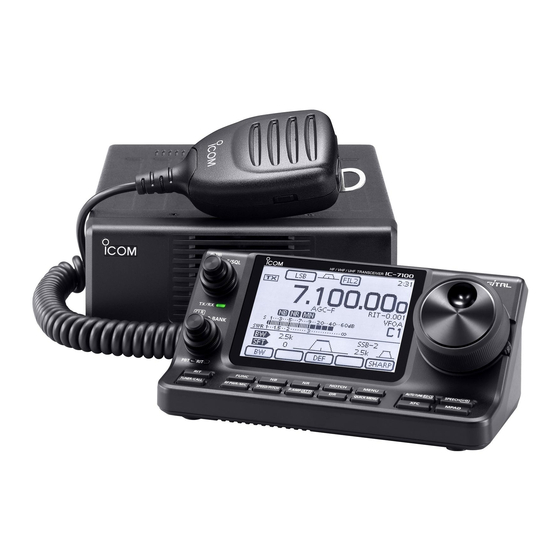
4. Remove all pieces of the ICOM-7100 radio from the kit.
a. Please note, if you do not need HF capability, you will not need the antenna tuner or
tuner cable.
5. If you need VHF/UHF capability, connect the coax cable from your antenna to the [ANT2] port
located on the outer edge of the main unit of the ICOM 7100.
6. Locate the shielded network cable (with silver RJ45 connections.) The ports on the main unit
and control head that you will connect this cable to are also silver.
SRCARES-250_7100Connections – Rev 1.0
ICOM 7100 Go-kit Connections
P a g e
| 1
AJT-07/18/21
Advertisement

Related Manuals for Icom 7100


Summary of Contents for Icom 7100
- Page 1 5. If you need VHF/UHF capability, connect the coax cable from your antenna to the [ANT2] port located on the outer edge of the main unit of the ICOM 7100. 6. Locate the shielded network cable (with silver RJ45 connections.) The ports on the main unit and control head that you will connect this cable to are also silver.
- Page 2 ICOM 7100 Go-kit Connections a. Connect one end of the cable to the main unit to the port labeled [CONTROLLER] b. Connect the other end of the network cable to the rear of the control head to the port labeled [MAIN UNIT] 7.
- Page 3 ICOM 7100 Go-kit Connections 9. Connect the four ponged Molex connector on the red/black DC power cable to the main unit’s [DC 13.8V] port. 10. Connect the PowerPole end of the same red/black DC power cable to the [OUT] port of the PWRgate PG40S.
- Page 4 ICOM 7100 Go-kit Connections 14. Verify the Power Supply is in the off position then insert the IEC connector end of the AC power cable to the IEC port on the rear of the power supply on the opposite side from the ring connectors and then plug into an AC power outlet.
- Page 5 ICOM 7100 Go-kit Connections 20. Locate the short coax jumper cable and connect one end to the antenna tuner port [RF IN]. 21. Connect the other end of the short coax jumper to the main unit port [ANT1]. 22. Connect the coax connection from the HF antenna to the antenna tuner port [ANTENNA].