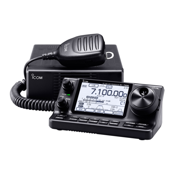
Icom IC-7100 Basic Manual
Hf/vhf/uhf all mode transceiver
Hide thumbs
Also See for IC-7100:
- Advanced instructions (375 pages) ,
- Service manual addendum (294 pages) ,
- Instruction manual (197 pages)
Table of Contents
Advertisement
BASIC MANUAL
HF/VHF/UHF ALL MODE TRANSCEIVER
i7100
This device complies with Part 15 of the FCC Rules. Operation
is subject to the following two conditions: (1) this device may
not cause harmful interference, and (2) this device must accept
any interference received, including interference that may cause
undesired operation.
WARNING: MODIFICATION OF THIS DEVICE TO RECEIVE
C E L L U L A R R A D I OT E L E P H O N E S E RV I C E S I G N A L S I S
PROHIBITED UNDER FCC RULES AND FEDERAL LAW.
Advertisement
Chapters
Table of Contents

Related Manuals for Icom IC-7100


Summary of Contents for Icom IC-7100
- Page 1 BASIC MANUAL HF/VHF/UHF ALL MODE TRANSCEIVER i7100 This device complies with Part 15 of the FCC Rules. Operation is subject to the following two conditions: (1) this device may not cause harmful interference, and (2) this device must accept any interference received, including interference that may cause undesired operation.
-
Page 2: Explicit Definitions
Equipment damage may occur. provide you with years of trouble-free operation. Recommended for optimum use. No risk We thank you for making your IC-7100 your radio of choice, NOTE of personal injury, fire or electric shock. and hope you agree with Icom’s philosophy of “technology first.”... - Page 3 OFF and remove the power cable if it emits an abnormal transceiver’s RF output power to less than the linear ampli- odor, sound or smoke. Contact your Icom dealer or dis- fier’s maximum input level, otherwise, the linear amplifier will tributor for advice.
-
Page 4: Supplied Accessories
SUPPLIED ACCESSORIES ABOUT THE SUPPLIED CD The following accessories are supplied with the transceiver. The following instructions and installers are included on the CD. q Hand microphone ..........1 w Control cable ............1 • Basic Manual e Ferrite EMI filter ........... 1 Instructions for the basic operations, the same as this For European versions .... -
Page 5: Table Of Contents
Section PANEL DESCRIPTION Controller — Front panel ............1-2 Controller — Function display ..........1-7 Controller — Multi-function keys ...........1-10 M-1 (M-1 menu) Display ............1-10 M-2 (M-2 menu) Display ............1-10 M-3 (M-3 menu) Display ............1-10 D-1 (D-1 menu) Display ............1-10 D-2 (D-2 menu) Display ............1-10 Function keys on M-1 display ..........1-10... -
Page 6: Panel Description
PANEL DESCRIPTION Controller — Front panel i7100 RF/SQL TX / RX M-CH BANK MENU NOTCH AUTO TUNE RX SPEECH � TUNER/CALL MIC/RF PWR SPEED/PITCH P.AMP ATT QUICK MPAD !0 !1 • When used as an RF gain/squelch control q POWER SWITCH•AF VOLUME [PWR]•[AF] (p. - Page 7 PANEL DESCRIPTION e TX/RX LED y PBT LED Lights green when the squelch opens, or a signal Lights green when the [M-CH/BANK] controls act ➥ is received. as the PBT control. Lights red when transmitting. • Push the [M-CH] switch to select PBT control. ➥...
- Page 8 PANEL DESCRIPTION Controller — Front panel (Continued) i7100 RF/SQL TX / RX M-CH BANK MENU NOTCH AUTO TUNE RX SPEECH � TUNER/CALL MIC/RF PWR SPEED/PITCH P.AMP ATT QUICK MPAD !7 !8 !2 NOISE BLANKER KEY (FM sec. 5) !5 PREAMP•ATTENUATOR KEY P.AMP (Mode: SSB/CW/RTTY/AM) ❍...
- Page 9 PANEL DESCRIPTION !6 NOTCH KEY !9 QUICK MENU KEY (FM sec. 5) QUICK NOTCH (Mode = Auto notch: SSB/AM/FM ➥ Push to open or close the Quick Menu window. Manual notch: SSB/CW/RTTY/AM) • The Quick Menu is used to quickly select various functions.
- Page 10 PANEL DESCRIPTION Controller — Front panel (Continued) i7100 RF/SQL TX / RX M-CH BANK MENU NOTCH AUTO TUNE RX SPEECH � TUNER/CALL MIC/RF PWR SPEED/PITCH P.AMP ATT QUICK MPAD @2 @3 @2 SPEECH•LOCK KEY @3 MEMO PAD KEY (FM sec. 11) MPAD SPEECH Push to sequentially call up the contents from the...
-
Page 11: Controller - Function Display
PANEL DESCRIPTION Controller — Function display q TX ICON (Mode: DV) Indicates either the displayed frequency can be ➥ “DSQL” appears when the digital call sign squelch transmitted, or not. function is ON. (FM sec. 9) ➥ “CSQL” appears when digital code squelch func- ➥... - Page 12 PANEL DESCRIPTION Controller — Function display (Continued) o CLOCK READOUT !4 MEMORY CHANNEL READOUT (FM sec. 11) Shows the current time. Shows the selected memory channel, scan edge ➥ channel or Call channel. • UTC time or local time can be selected. •...
- Page 13 PANEL DESCRIPTION !9 FUNCTION ICONS (Mode: DV) “VOX” appears when the VOX function is activat- “ ” appears when the EMR (Enhanced Moni- ➥ ➥ ed. (FM sec. 6) tor Receive) communication mode is selected. The Break-in icons appear when the Break-in (FM sec.
-
Page 14: Controller - Multi-Function Keys
PANEL DESCRIPTION Controller — Multi-function keys Function keys on M-1 display Push to change the set of functions assigned ➥ MENU to touch keys. SCAN KEY [SCAN] (FM sec. 12) • Toggles the function display menu between M-1, M-2 and Touch to display the “SCAN”... -
Page 15: D Function Keys On M-3 Display
PANEL DESCRIPTION AGC KEY [AGC] (FM sec. 5) (Mode: SSB/SSB-D/CW/RTTY/AM/AM-D) RTTY SET KEY [RTTY] (FM sec. 6) ➥ Touch to select the time constant of the Touch to display the “RTTY SET” screen. AGC circuit. • Push to return to the previous screen. MENU ➥... -
Page 16: D Function Keys On D-1 Display
PANEL DESCRIPTION Controller — Multi-function keys Function keys on M-3 display (Continued) VOICE RECORDER KEY [VOICE] (FM sec. 15) This function requires to insert an SD card. VOX KEY [VOX] (FM sec. 6) Touch to display the “VOICE TX” screen or (Mode: SSB/AM/FM/DV) the “VOICE”... -
Page 17: Controller - Rear And Bottom Panels
PANEL DESCRIPTION Controller — Rear and bottom panels Bottom panel Rear panel Speaker q HEADPHONE/SPEAKER JACK [PHONES/SP] e MICROPHONE CONNECTOR [MIC] Plug in standard stereo headphones (impedance: 8 Plug in the supplied or an optional microphone. to 16 ø • See FM sec. 21 for appropriate microphones. •... -
Page 18: Main Unit - Front Panel
PANEL DESCRIPTION Main unit — Front panel q COOLING FAN w SD CARD SLOT [SD CARD] This is a cooling fan for heat dissipation. Insert an SD card of up to 32 GB SDHC. Depending on the internal temperature, it rotates at See FM sec. - Page 19 , for external control of the transceiver. converter “DATA OFF MOD” or “DATA MOD.” The modulation ➥ Use for the transceive function with another Icom input level from the USB jack can be set in the Set CI-V transceiver or receiver.
-
Page 20: Dacc Socket Information
“1SS133,” on the load side of the circuit to the counter-electromotive force absorption. When the diode is added, a switching delay of the relay may occur. Be sure to check its switching action before operation. [Example] Switching diode To a non-Icom ACC socket linear amplifier eHSEND or uVSEND Relay i13.8 V... -
Page 21: Ddata2 Socket Information
PANEL DESCRIPTION • When connecting the ACC conversion cable (OPC-599) Connect to ACC socket ACC 1 ACC 2 q FSKK t AF q 8 V t ALC w GND y SQLS w GND y VSEND e HSEND u 13.8 V e HSEND u 13.8 V r MOD... -
Page 22: Microphone
PANEL DESCRIPTION Microphone HM-198 (Supplied) q PTT SWITCH Hold down to transmit, release to receive. w UP/DOWN KEYS [UP]/[DN] Push either key to change the operating frequen- ➥ cy, memory channel, Set mode setting, and so on. (p. 3-9, FM sec. 4, 11) Hold down either key for 1 second to start scan- ➥... -
Page 23: D Hm-151 (Option)
> SPEECH > S-Level SPEECH • When RIT is ON, the RIT offset is not included in the • Icom’s triple band stacking register memorizes 3 fre- frequency announcement. quencies in each band. ❍ LOCK KEY Operation (FM sec. 5) - Page 24 PANEL DESCRIPTION Microphone HM-151 (Option) (Continued) SPCH TUNER /LOCK /CALL Mic element MODE GENE F-INP u MODE KEY [MODE] !2 TRANSMIT FREQUENCY CHECK KEY [XFC] Push to cycle through the operating modes: ➥ During split frequency or repeater operation, hold ➥...
- Page 25 Required Connections to a Transceiver ........2-5 The External Units Connections to a Transceiver ....2-6 Power Supply Connections ............2-7 Connecting the PS-126 power supply ........2-7 Connecting a non-Icom DC power supply .......2-7 Linear Amplifier Connections ..........2-8 Connecting the IC-PW1/EURO ..........2-8 Connecting a non-Icom linear amplifier ........2-8...
-
Page 26: Antenna Connection
Controller bottom view antenna tuner is useful to match the transceiver and antenna. Low SWR allows full power for transmit- ting. The IC-7100 has an SWR meter to continuously monitor the antenna SWR. Grounding To prevent electrical shock, television interference... -
Page 27: The Main Unit Installation
Drill 5 mm holes for the bracket location. Spring washer Drill 3 mm holes for the tapping screws. MB-62 Main unit installation Flat washer The MB-62 can be used for AT-180 as well. Adjust for the best angle. Screw Frange bolt Using tapping screws IC-7100... - Page 28 This could damage the transceiver. The • Data transmission (AFSK) HM-151 is designed to use with the IC-7000/ Connect TNC (Terminal Node Controller) to [MIC] connector to IC-7100 series ONLY. enable data transmission(AFSK). (FM sec 18) Connect to the [CONTROLLER] Controller connector of the Main unit [PHONES/SP] (Headphone/External Speaker)...
-
Page 29: Required Connections To Transceiver
74.8 MHz. 144/430 MHz frequency bands or least 22 Am- 74.8 MHz and above. peres. IC-7100 [MIC] MODULAR MICRO- PHONE CONNECTOR (p. 2-4) As with a microphone connec- tor of the controller, accepts the supplied microphone. - Page 30 INSTALLATION AND CONNECTIONS The External Units Connections to a Transceiver [TUNER] TUNER CONTROL SOCKET (FM sec.16) [DATA1] DATA1 JACK FM sec. 10 For GPS operation ( • Connect a GPS receiver to the transceiv- Connect the con- trol cable from an •...
-
Page 31: Connecting The Ps-126 Power Supply
• DC 13.8 V (Capacity: 22 A and over) necting the DC power cable. • A power supply with an over current protective line • We recommend using Icom’s optional power supply and with a less voltage fluctuation or ripple (PS-126: DC13.8 V/25 A). -
Page 32: Connecting The Ic-Pw1/Euro
INSTALLATION AND CONNECTIONS Linear Amplifier Connections Connecting the IC-PW1/EURO To connect the Icom IC-PW1/EURO, see the diagram below. For IC-PW1/EURO operation, refer to the amplifier’s instruction manual. ACC cable 7-pin side To an antenna [ACC-1] OPC-599 conversion Remote Control [REMOTE]... - Page 33 Section Section BASIC OPERATION BASIC OPERATION Power ON ..................3-2 Before first applying power ............3-2 Tuning ON the power ...............3-2 Selecting a Function menu .............3-3 Selecting VFO/Memory mode ..........3-4 VFO operation ................3-5 Selecting VFO A or VFO B ............3-5 VFO equalization ..............3-5 Selecting a frequency band ............3-6 Using the band stacking registers...
-
Page 34: Before First Applying Power
BASIC OPERATION Power ON Before first applying power Before turning ON your transceiver for the first time, NOTE: When turning OFF the power, the transceiver make sure all connections required for your system are memorizes the settings. Thus the transceiver restarts complete by reviewing them in Section 2 of this man- with the settings before you turned OFF the power. - Page 35 BASIC OPERATION Selecting a Function menu Push (C) one or more times to select the “M-1” MENU screen (M-1 menu), “M-2” screen (M-2 menu) or “M-3” screen (M-3 menu). • In the DR mode, push (C) once or twice to select the MENU “D-1”...
- Page 36 BASIC OPERATION Selecting VFO/Memory mode IC-7100 has VFO and Memory modes. VFO mode icon In the VFO mode, rotate the Dial to select the disired frequency. In the Memory mode, rotate [M-CH] (L) to select the preprogrammed memory channel. Push (C) one or more times to select the “M-1”...
-
Page 37: D Vfo Equalization
BASIC OPERATION VFO operation The IC-7100 has two VFOs; “A” and “B,” and are conve- The L, R, C or D in the in- L eft D isplay R ight nient for quickly selecting two frequencies, or split fre- structions indicate the part quency operation. -
Page 38: D Using The Band Stacking Registers
BASIC OPERATION Selecting a frequency band Select the frequency band you want to use. Touch the MHz Touch the MHz digits of the frequency readout to en- digits. ter the Band selection screen. Touch a desired operating band, “1.8” to “430” or “GENE.”... -
Page 39: Tuning With The Dial
BASIC OPERATION Setting frequency You can select the transceiver’s frequency by using the Dial, or you can enter it on the Direct input screen. Tuning with the Dial q On the Band selection screen, select the desired fre- quency band. (p. 3-6) Dial w Rotate the Dial to set the desired frequency. -
Page 40: D Quick Tuning Function
BASIC OPERATION Setting frequency (Continued) Quick Tuning function The operating frequency can be changed in ‘kHz’ or ‘MHz’ steps for quick tuning. Select the desired tuning step in each operating fre- • ‘kHz’ Quick Tuning function quency band and mode. q Touch the kHz digits to select the ‘kHz’... -
Page 41: D Selecting 1 Hz Step
BASIC OPERATION Setting frequency (Continued) Selecting ‘kHz’ step When the ‘kHz’ Quick Tuning is selected, the frequen- cy can be changed in the selected ‘kHz’ steps. The steps can be memorized, depending on the operating modes. On the Mode selection screen, select the desired op- erating mode. -
Page 42: D Auto Tuning Step Function
BASIC OPERATION Setting frequency (Continued) 1/4 tuning step function (Mode: SSB-D/CW/RTTY) The dial speed is reduced to ⁄ of the normal speed when the ⁄ tuning function is ON, for finer tuning con- trol. You can set the ⁄ tuning function in each operating frequency band. -
Page 43: Direct Frequency Input
BASIC OPERATION Setting frequency (Continued) Direct frequency input The transceiver has a Direct input screen for direct fre- The L, R, C or D in the in- L eft D isplay R ight quency entry, as described below. structions indicate the part of the controller. - Page 44 BASIC OPERATION Setting frequency (Continued) Direct frequency input (Continued) • Split offset frequency input Touch the MHz digits to enter the Band selection dis- play. Touch the MHz Touch [F-INP]( D) to enter the Direct input screen. digits If the Shift direction is minus, touch “• (–).” •...
-
Page 45: D Band Edge Warning Beep
BASIC OPERATION Setting frequency (Continued) Band edge warning beep You can hear a beep tone when you tune into or out of an amateur band’s frequency range. A regular beep sounds when you tune into a range, and an lower tone error beep sounds when you tune out of a range. -
Page 46: D Programming The User Band Edge
BASIC OPERATION Setting frequency (Continued) Programming the user band edge When “ON (User)” or “ON (User) & TX Limit” is selected in the “Band Edge Beep” item, the “User Band Edge” item appears in the “Function” Set mode. A total of 30 band edge frequencies can be programmed in the “User Band Edge”... - Page 47 BASIC OPERATION Setting frequency (Continued) Programming the user band edge (Continued) • Inserting a Band edge Example: Inserts the 1.800–1.999999 MHz range Enter the “User Band Edge” screen. Touch the Band Function > User Band Edge (C) > edge for 1 sec- Touch for 1 second the Band edge that you want to insert a new Band edge above it.
- Page 48 BASIC OPERATION Setting frequency (Continued) Programming the user band edge (Continued) Example: Change the 7.000–7.300000 MHz range • Changing the Band edge frequencies Enter the “User Band Edge” screen. Function > User Band Edge (C) > Touch the Band edge to be changed. Touch the de- •...
- Page 49 BASIC OPERATION Selecting the Operating mode The usable operating modes in the IC-7100 are listed to the right below. You can select the desired operating mode by touching the mode key on the Mode selection screen. NOTE: Touch the Mode...
- Page 50 BASIC OPERATION Selecting the Audio volume Rotate [AF] (L) control clockwise to increase the ➥ audio output level, counterclockwise to decrease it. Increases [AF] Decreases The L, R, C or D in the in- L eft D isplay R ight structions indicate the part of the controller.
- Page 51 BASIC OPERATION Squelch and receive (RF) sensitivity Adjusts the RF gain and squelch threshold level. The The L, R, C or D in the instructions indicate the squelch removes noise output to the speaker when no part of the controller. signal is received (closed squelch).
- Page 52 BASIC OPERATION Voice synthesizer operation The IC-7100 has a built-in voice synthesizer to an- The L, R, C or D in the in- L eft D isplay R ight nounce the operating frequency, mode and S-meter structions indicate the part level in a clear, electronically-generated voice, in Eng- of the controller.
-
Page 53: Tuning On The Mode Announcement
BASIC OPERATION Voice synthesizer operation (Continued) Tuning OFF the S-meter announcement The S-meter announcement can be turned OFF. Push (C) to enter the Set mode. Touch the “S-Level SPEECH” item of the “SPEECH” Set mode. SPEECH > S-Level SPEECH Touch •... - Page 54 BASIC OPERATION Meter display selection The transmit meter can be toggled between four func- tions for your convenience. ➥ Touch the Meter one or more times to select the TX meter function, RF power meter, SWR meter, ALC meter or COMP meter. •...
-
Page 55: Basic Transmit Operation
BASIC OPERATION Basic transmit operation The L, R, C or D in the in- L eft D isplay R ight Before transmitting, monitor the operating fre- structions indicate the part quency to make sure transmitting won’t cause of the controller. interference to other stations on the same fre- L: Left side quency. -
Page 56: D Microphone Gain Adjustment
BASIC OPERATION Basic transmit operation (Continued) Microphone gain adjustment (Mode: SSB/AM/FM/DV) Push (C) to open the MIC gain/RF power MIC/RF PWR TX/RX LED adjustment display. Push [PTT] to transmit. • Speak into the microphone at your normal voice level. Rotate [M-CH] (L) to adjust the MIC gain. - Page 57 Section D-STAR INTRODUCTION “MY” (Your own call sign) programming ......4-2 D-STAR Introduction .............4-5 About the DR (D-STAR Repeater) mode ......4-5 Communication Form in the DR mode ........4-6 Section 1 PANEL DESCRIPTION Section 2 INSTALLATION AND CONNECTIONS Section 3 BASIC OPERATION Section 4 D-STAR INTRODUCTION Section 5 D-STAR OPERATION <BASIC>...
- Page 58 D-STAR INTRODUCTION “MY” (Your own call sign) programming Before starting D-STAR, the following steps are needed. IMPORTANT! Entering your call sign (MY) into the transceiver. Registering your call sign STEP 1 STEP 2 (MY) to a gateway repeater. You have completed the steps!! You can store up to 6 “MY”...
- Page 59 D-STAR INTRODUCTION “MY” (Your own call sign) programming (Continued) Enter the Call Sign The L, R, C or D in the L eft D isplay R ight instructions indicate the Touch the desired block one or more times to select part of the controller.
- Page 60 D-STAR INTRODUCTION “MY” (Your own call sign) programming 2. Enter the Call Sign (Continued) The L, R, C or D in the L eft D isplay R ight instructions indicate the Touch the entered call sign to set the call sign to be part of the controller.
- Page 61 D-STAR INTRODUCTION D-STAR Introduction • In the original D-STAR (Digital Smart Technologies for Amateur Radio) plan, JARL envisioned a system of repeaters grouped together into Zones. • The D-STAR repeater enables you to call a HAM sta- tion on another repeater through the internet. •...
- Page 62 D-STAR INTRODUCTION Communication Form in the DR mode In the DR mode, the transceiver has three communica- tion forms, as shown below. • Local area call: To call through your local area (ac- cess) repeater. • Gateway call: To call through your local area (ac- cess) repeater, repeater gateway and the internet to your destination re- peater or individual station’s last used...
- Page 63 Section D-STAR OPERATION <BASIC> D-STAR Operating procedures ..........5-2 Making a Local area call ............5-2 Making a Gateway call ............5-3 About “UR?” and “RPT?” error messages ......5-5 Shows “UR?” .................5-5 Shows “RPT?” or “RX” ............5-5 Shows “L” ................5-5 Capturing a call sign .............5-6 “FROM”...
-
Page 64: D-Star Operation
D-STAR OPERATION <BASIC> D-STAR Operating procedures This section describes the basic D-Star procedures. • When it is the first time to operate D-STAR, check Touch whether or not you can access your local area repeat- “FROM.” er (Access repeater), and if your signal is successfully sent to a destination repeater. -
Page 65: D Making A Gateway Call
D-STAR OPERATION <BASIC> D-STAR Operating procedures (Continued) Making a Gateway call Set “FROM” (Access repeater) Push (C) to select the DR mode. Touch Check whether or not “FROM” is selected. “FROM.” • If “FROM” is not selected, touch the “FROM” field. “FROM”... - Page 66 D-STAR OPERATION <BASIC> D-STAR Operating procedures (Continued) < Communication example for a Gateway call> INTERNET JA3YUA calling JP1YIU port A through JP3YHH port B. JA3YUA, this is JM1ZLK. Hello, how are you? • • • JM1ZLK, this JA3YUA. Thanks for the nice QSO and I hope to talk to you again soon.
-
Page 67: About "Ur?" And "Rpt?" Error Messages
D-STAR OPERATION <BASIC> About “UR?” and “RPT?” error messages The transceiver includes a status message in the signal received back from the access repeater, after transmit- ting. Shows “UR?” The call was successfully sent, but no station’s signal was received within 3 seconds. The called station may have missed your call, so after waiting for a while, try calling again. -
Page 68: Capturing A Call Sign
D-STAR OPERATION <BASIC> Capturing a call sign After you receive the repeater’s signal, the calling sta- The L, R, C or D in the L eft D isplay R ight tion’s call sign can be captured by holding down the instructions indicate the part of the controller. -
Page 69: From" (Access Repeater) Setting
D-STAR OPERATION <BASIC> “FROM” (Access repeater) setting Your access repeater must be set to “FROM” when you transmit a call in the DR mode. You have four ways to set the access repeater. “Hirano” repeater Click the title shown below to jump to the specified is set in “FROM.”... -
Page 70: D Sing The Preloaded Repeater List
D-STAR OPERATION <BASIC> “FROM” (Access repeater) setting (Continued) Using the preloaded repeater list When your access repeater is preloaded in your trans- ceiver’s repeater list, you can select it from the repeater list. By only selecting the repeater from the list, the call Touch sign, frequency, duplex and offset frequency settings “FROM.”... -
Page 71: U D Sing The Dr Mode Scan
D-STAR OPERATION <BASIC> “FROM” (Access repeater) setting (Continued) Using the DR mode scan The L, R, C or D in the L eft D isplay R ight instructions indicate the The DR mode scan is useful to find a repeater. part of the controller. -
Page 72: D Using The Repeater Search Function
D-STAR OPERATION <BASIC> “FROM” (Access repeater) setting (Continued) Using the Repeater Search function The L, R, C or D in the instructions indicate the The transceiver searches for the nearest repeater by part of the controller. using your own and the repeater’s position. L: Left side, R: Right side, C: Center bottom The nearest repeater in your transceiver’s repeater list D: Display (Touch screen) - Page 73 D-STAR OPERATION <BASIC> “FROM” (Access repeater) setting Using the Repeater Search function (Continued) Selecting the access repeater from the Near Re- peater list Push (C) to select the DR mode. Touch Check whether or not “FROM” is selected. “FROM” • If “FROM” is not selected, touch the “FROM” field. Touch the “FROM”...
-
Page 74: D Sing The Tx History
D-STAR OPERATION <BASIC> “FROM” (Access repeater) setting (Continued) Using the TX History The L, R, C or D in the L eft D isplay R ight instructions indicate the Repeaters you transmitted to in the DR mode are stored part of the controller. in the TX History, and you can select a repeater from the TX History as your access repeater. -
Page 75: To" (Destination) Setting
D-STAR OPERATION <BASIC> “TO” (Destination) setting The destination repeater or station must be set to “TO” when you transmit a call in the DV mode. “Hamacho” You have eight ways to set the destination. repeater is set in “TO.” Click the title shown below to jump to the specified page. -
Page 76: D Using The "Local Cq" (Local Area Call)
D-STAR OPERATION <BASIC> “TO” (Destination) setting (Continued) Using the “Local CQ” (Local Area call) The L, R, C or D in the L eft D isplay R ight instructions indicate the When “Local CQ” is selected in the “TO SELECT” part of the controller. -
Page 77: D Using The "Gateway Cq" (Gateway Call)
D-STAR OPERATION <BASIC> “TO” (Destination) setting (Continued) Using the “Gateway CQ” (Gateway call) The L, R, C or D in the L eft D isplay R ight instructions indicate the When “Gateway CQ” is selected in the “TO SELECT” part of the controller. screen, the repeater to make a gateway CQ call can be selected from the repeater list. -
Page 78: D Sing The "Your Call Sign
D-STAR OPERATION <BASIC> “TO” (Destination) setting (Continued) Using the “Your Call Sign” The L, R, C or D in the L eft D isplay R ight instructions indicate the The “Your Call Sign” memory stores the programmed part of the controller. “UR”... -
Page 79: U D Sing The Rx History
D-STAR OPERATION <BASIC> “TO” (Destination) setting (Continued) Using the RX History The L, R, C or D in the L eft D isplay R ight instructions indicate the When a call is received in the DV mode, the call data is part of the controller. - Page 80 D-STAR OPERATION <BASIC> “TO” (Destination) setting (Continued) Using the TX History The L, R, C or D in the instructions indicate the The TX History stores the name and/or call sign of up part of the controller. to 20 “TO” (Destination) settings that were used when L: Left side, R: Right side, C: Center bottom you made the calls.
- Page 81 D-STAR OPERATION <BASIC> “TO” (Destination) setting (Continued) Directly inputting (UR) The L, R, C or D in the L eft D isplay R ight instructions indicate the The destination station call sign can be directly input. part of the controller. Example: Directly input the call sign “JM1ZLK.”...
-
Page 82: U D Irectly Inputting (Ur)
D-STAR OPERATION <BASIC> “TO” (Destination) setting (Continued) Directly inputting (RPT) Touch The destination repeater call sign can be directly input. “TO.” Example: Directly input the call sign “JP3YDH” Push (C) to select the DR mode. Check whether or not “TO” is selected. •... -
Page 83: Section 1 Panel Description
Section SET MODE Set mode description ............6-2 The Set mode settings ............6-2 Set mode items and Default settings ........6-3 Section 1 PANEL DESCRIPTION Section 2 INSTALLATION AND CONNECTIONS Section 3 BASIC OPERATION Section 4 D-STAR INTRODUCTION Section 5 D-STAR OPERATION <BASIC> Section 6 SET MODE Section 7 CE ‘FM’... - Page 84 SET MODE Set mode description The Set mode is used to program infrequently changed The L, R, C or D in the L eft D isplay R ight instructions indicate the values or function settings. part of the controller. NOTE: The Set mode is constructed in a tree struc- L: Left side ture.
- Page 85 SET MODE Set mode items and Default settings Call sign (FM sec. 9) GPS (FM sec. 10) ➥ ➥ RX History (FM sec. 9) SD Card (FM sec. 13) ➥ ➥ MY Station (Section 4) ➥ NOTE: The default settings shown below in bold are for the USA version. The default settings may differ, depending on your transceiver version.
- Page 86 SET MODE Set mode items and Default settings (Continued) NOTE: The default settings shown below in bold are for the USA version. The default settings may differ, depending on your transceiver version. SPEECH In this item, set the Speech options. OFF, ON (Kerchunk) or ON (All) RX Call Sign SPEECH Selects the RX call sign speech function option...
- Page 87 Auto, SQL or RF+SQL Select the function of the [RF/SQL] control. TX Delay OFF, 10ms, 15ms, 20ms, 25ms or Sets the transmission’s timing of the IC-7100 to 30ms prevent any external equipment that is connected from damage by the transmitted RF.
- Page 88 SET MODE Set mode items and Default settings (Continued) NOTE: The default settings shown below in bold are for the USA version. The default settings may differ, depending on your transceiver version. OFF or ON PTT Start Turns the PTT Tuner Start function ON or OFF. Manual or Auto [TUNER] Switch Selects whether or not to store the AT-180’s sta-...
- Page 89 SET MODE Set mode items and Default settings (Continued) NOTE: The default settings shown below in bold are for the USA version. The default settings may differ, depending on your transceiver version. Tone Control In this item, set the RX/TX tone control options. RX HPF/LPF ---- –...
- Page 90 SET MODE Set mode items and Default settings (Continued) NOTE: The default settings shown below in bold are for the USA version. The default settings may differ, depending on your transceiver version. Connectors In this item, set the external connector’s options. OFF (OPEN) or ON USB Audio SQL Selects whether or not to output the audio from...
- Page 91 SET MODE Set mode items and Default settings (Continued) NOTE: The default settings shown below in bold are for the USA version. The default settings may differ, depending on your transceiver version. Display In this item, set the transceiver’s display options. LCD Contrast 0%~50%~100% Sets the contrast level of the LCD.
- Page 92 Reads or writes the CS-7100 data to or from the PC, and/or receives data from a Master trans- ceiver. Clone Master Mode Writes your IC-7100 (Master) data to another IC- 7100 (Sub). Touch Screen Calibration Adjusts the touch screen. Reset...
- Page 93 Section Installation notes ..............7-2 Country code list ..............7-3...
- Page 94 Installation notes EIRP clearance heights by frequency band For amateur base station installations it is recom- mended that the forward clearance in front of the an- Watts 10–2 m 70 cm 23 cm 13 cm and above 2.1 m tenna array is calculated relative to the EIRP (Effective Isotropic Radiated Power).
- Page 95 Country code list • ISO 3166-1 Country Codes Country Codes Austria Liechtenstein Belgium Lithuania Bulgaria Luxembourg Croatia Malta Czech Republic Netherlands Cyprus Norway Denmark Poland Estonia Portugal Finland Romania France Slovakia Germany Slovenia Greece Spain Hungary Sweden Iceland Switzerland Ireland Turkey Italy United Kingdom...
- Page 96 IC-7100 #05 < Intended Country of Use > (Italy) IC-7100 #06 < Intended Country of Use > (Spain) IC-7100 #12 < Intended Country of Use > (France) A-7085H-1EX-q Printed in Japan 1-1-32 Kamiminami, Hirano-ku, Osaka 547-0003, Japan © 2013 Icom Inc.