Table of Contents
Advertisement
Quick Links
Advertisement
Table of Contents

Related Manuals for Stanley Enerpac PRO Series


Summary of Contents for Stanley Enerpac PRO Series
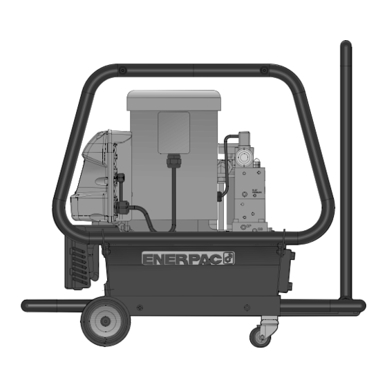
- Page 1 Enerpac PRO Series Pumps ® PRO115E-A...
- Page 2 Pump & AV Tool Operator Guide Original Instruction Enerpac PRO Series Pump Hydraulic Power Unit...
-
Page 3: Table Of Contents
STANLEY Engineered Fastening will not accept any liability for damage resulting from activities carried out by third parties. The working names, trade names, registered trademarks, etc. used by STANLEY Engineered Fastening should not be considered as being free, pursuant to the legislation with respect to the protection of trademarks. -
Page 4: Safety Definitions
• Only qualified and trained operators must install, adjust or use the equipment. • DO NOT use outside the design intent of placing STANLEY Engineered Fastening Blind Rivets. • Use only parts, fasteners, and accessories recommended by the manufacturer. •... -
Page 5: Projectile Harzards
• The equipment must be maintained in a safe working condition at all times and examined at regular intervals for damage and function by trained personnel. Any dismantling procedure will be undertaken only by trained personnel. Do not dismantle this equipment without prior reference to the maintenance instructions. 1.2 PROJECTILE HARZARDS •... -
Page 6: Accessory Hazards
employer and consult a qualified health professional. 1.5 ACCESSORY HAZARDS • Disconnect the tool from the hydraulic pump before fitting or removing the nose assembly or accessory. • Use only sizes and types of accessories and consumables that are recommended by the manufacturer of the tool; do not use other types or sizes of accessories or consumables. - Page 7 • Maximum temperature of the hydraulic fluid at the inlet is 110°C (230°F). STANLEY Engineered Fastening policy is one of continuous product development and improvement and we reserve the right to change the specification of any product without prior notice.
-
Page 8: Specification
SPECIFICATION INTENT OF USE The pump unit may only be used in accordance with the operating instructions for Stanley Engineered Fastening placing tools and for placing Stanley Engineered Fastening rivets. The pump unit is an electrically driven, hydraulic power source. When coupled to a compatible Stanley Engineered Fastening ®... -
Page 9: Pump Models
PUMP MODELS Pump Models 76501-02000 / 76501-02500 / 76502-02000 / 76502-02500 PUMP SPECIFICATION PART NUMBER 76501-02000 76501-02500 76502-02000 76502-02500 Name PRO115-A PRO115-F PRO220-A PRO220-F Pump Model: Enerpac ® Pump Series Valve Part Number VE42TQ-115V VE42TQ-115V VE42TQ-230V VE42TQ-230V Motor: Power (kW) 1.12 1.12 1.12... - Page 10 Pump Models 76503-02000 / 76503-02500 / 76504-02000 / 76504-02500 PUMP SPECIFICATION PART NUMBER 76503-02000 76503-02500 76504-02000 76504-02500 Name PRO240-A PRO240-F PRO415-A PRO415-F Pump Model: ® Enerpac Pump Series Valve Part Number VE42TQ-24V VE42TQ-24V VE42TQ-24V VE42TQ-24V Motor: Power (kW) 1.12 1.12 1.12 1.12 Voltage (V)
- Page 11 Pump Models 76505-02000 / 76505-02500 / 76506-02000 / 76507-2000 PUMP SPECIFICATION PART NUMBER 76505-02000 76505-02500 76506-02000 76507-02000 Name PRO480-A PRO480-F PRO115E-A PROE220E-A Pump Model: ® Enerpac Pump Series Valve Part Number VE42TQ-24V VE42TQ-24V VE42TQ-230V VE42TQ-230V Motor: Power (kW) 1.12 1.12 1.25 1.25 Voltage (V)
- Page 12 Pump Models 76506-02300 / 76507-02300 / 76508-02000 / 76508-02500 PUMP SPECIFICATION PART NUMBER 76506-02300 76507-02300 76508-02000 76508-02500 Name PRO115E-D PROE220E-D PRO240 PLUS-A PRO240 PLUS-F Pump Model: ® Enerpac Pump Series Valve Part Number VE42TQ-115V VE42TQ-230V VE42TQ-24V VE42TQ-24V Motor: Power (kW) 1.25 1.25 Voltage (V)
- Page 13 Pump Models 76510-02000 / 76510-02500 / 76511-02000 / 76511-02500 PUMP SPECIFICATION PART NUMBER 76510-02000 76510-02500 76511-02000 76511-02500 Name PRO415 PLUS-A PRO415 PLUS-D PRO480 PLUS-A PRO480 PLUS-D Pump Model: ® Enerpac Pump Series Valve Part Number VE42TQ-24V VE42TQ-24V VE42TQ-24V VE42TQ-24V Motor: Power (kW) Voltage (V) 380-415...
-
Page 14: Pump Unit Dimensions
PUMP UNIT DIMENSIONS Pump Models 76501-02000 / 76503-02000 / 76504-02000 / 76505-02000 / 76508-02000 / 76510-02000 / 76511-02000 Pump Models 76501-02500 / 76503-02500 / 76504-02500 / 76505-02500 / 76508-02500 / 76510-02500 / 76511-02500 Pump Models 76506-02000 / 76507-02000 All dimensions are shown in millimetres... - Page 15 PUMP UNIT DIMENSIONS Pump Models 76506-02300 / 76507-02300 All dimensions are shown in millimetres.
-
Page 16: Putting Into Service
The PRO units are high pressure hydraulic pumps delivering two different operating pressures for the pull and return cycle of Stanley Engineered Fastening placing tools; High pressure (c510bar) during the pull cycle and a lower pressure (c200bar) during the return cycle. -
Page 17: Preparation For Use
PREPARATION FOR USE • Position the pump to ensure that air flow around the motor and cooling fan is unobstructed. Keep the motor and cooling fan clean to ensure maximum cooling during operation. • For shipping purposes, a red shipping plug (A) is installed in the breather port on the top of the reservoir. Before using, replace the shipping plug with the black breather cap supplied. -
Page 18: Pump Lcd Menus And Operating Instructions
prevents the motor from starting. The LCD screen will display ‘BUTTON FAULT’ in this instance. Reset by switching off the power supply for 10 seconds. • Depress and release the placing tool trigger switch a few times to almost the full stroke of the tool to circulate hydraulic fluid. - Page 19 LCD Menus • The software provides the operator with the following Menus: • RET TIME – This screen allows the operator to set the value of the Return Timer. This timer controls the time that the pump motor will continue to run, after releasing the trigger or achieving the ‘High Pressure’ value, before switching to the idle mode.
- Page 20 • MOTOR – This screen displays the number of hours or On/Off cycles the motor has been operated. Toggle between Hours and Cycles by pressing the Down or Up Arrow buttons. The counter is non-resettable. Save the setting and step forward using the MENU button.
- Page 21 • RETRACT – This screen displays the number of hours (On/Off cycles) the Retract solenoid has been operated. This is the placing tool return cycle. Toggle between HOURS and CYCLES by pressing either the Down or Up Arrow buttons. Step forward by pressing the MENU button.
-
Page 22: Return Timer Setting
• DIAGNOSE – This screen allows the operator to troubleshoot connection issues between the placing tool and the pump by displaying if the microprocessor has received a signal from the trigger button. No signal indicates the problem is most likely with the trigger or trigger control cord. SCREEN 12 DIAGNOSE 00001... -
Page 23: Pressure Settings
PRESSURE SETTINGS Note: This is not applicable to pump models 76506-02000 and 76507-02000 – refer to section 3.6. • The pump has two methods for limiting the pull / advance pressure to the placing tool and further pressure relief valve for limiting the return pressure. - Page 24 • Tighten the relief valve locking nut. • Release the Up Arrow button. Then recheck the final pressure setting by pressing the Up Arrow and pressurising the system. • De-activate the LOCAL mode by displaying the ‘LOCAL’ menu and toggling the setting to ‘OFF’. Save the setting by pressing the MENU button once.
-
Page 25: Pump Operating Instructions - Models 76506-02000 & 76507-02000
• Tighten the jam nut when the desire pressure is set and then replace the copper gasket and acorn nut. Then recheck the final pressure setting by pressing the MOTOR On/Off button once and pressurising the system. • De-activate the LOCAL mode by displaying the ‘LOCAL’ menu and toggling the setting to ‘OFF’. Save the setting by pressing the MENU button once. -
Page 26: Priming The Hose Set
Relieving Pressure: To relieve hydraulic pressure held in the tool and hoses: • Press and hold the “Motor Off” button. • While continuing to hold down the “Motor Off” button, press and release the “Tool Trigger” three or more times, until the pressure gauge reads 0 psi/bar. -
Page 27: Servicing The Pump Unit
DAILY / WEEKLY IMPORTANT - Only fully trained and qualified hydraulic technicians should service the pump or system components. Please contact Stanley Engineered Fastening for your servicing, repair and training requirements. Service Instructions and repair parts sheet are available on request. -
Page 28: Changing The Filter Element
CHANGING THE FILTER ELEMENT A return line filter may be ordered as an accessory to the pump. The filter element should be replaced every 250 hours, or more frequently in dirty environments. The filter manifold is equipped with a 25 psi (1.7 bar) bypass to prevent over pressure rupture if filter plugging occurs. -
Page 29: Fault Diagnosis
IMPORTANT - Only fully trained and qualified hydraulic technicians should service the pump or system components. Please contact Enerpac or Stanley Engineered Fastening for your servicing, repair and training requirements. Service Instructions and repair parts sheet are available on request. - Page 30 SYMPTOM POSSIBLE CAUSE REMEDY PAGE REF. Add oil - refer to Putting into Low oil level Service and Maintenance and 13, 14, 23, 24 Servicing Adjust Pull/Advance Pressure Relief valve set too low Relief Valve and High Pressure 20, 21 Pump fails to build setting pressure or less than...
-
Page 31: Fault Conditions
FAULT CONDITIONS Note: This is not applicable to pump models 76506-02000 and 76507-02000. • Any fault will shut down and prevent pump from starting. Clearing a Fault Condition from the LCD • After the fault causing problem has been corrected, clear the fault message from the LCD by disconnecting electrical power from the pump, wait until all characters clear the LCD (~ 10 seconds), then reconnect power. -
Page 32: Warranty Statement
WARRANTY STATEMENT This product is warranted by ENERPAC ® in accordance to the warranty terms as provided on their website at: http://www.enerpac.com/en/warranty. Seller agrees to co-operate with Buyer and to render assistance in enforcing ENERPAC’s warranties where necessary. - Page 33 Manual Number Issue 07900-01030 22/033 © 2017 Stanley Black & Decker, lnc. www.StanleyEngineeredFastening.com © 2017 Stanley Black & Decker, Inc., Rev. 08.2016 Avdel , NeoBolt , Avseal , Avdelok , Monobolt , AvBolt and Avtainer are registered trademarks of Avdel UK Limited.
- Page 34 Instruction Sheet POWERFUL SOLUTIONS. GLOBAL FORCE. ZU4 Classic Torque Wrench Pump L2906 Rev. C 12/10 Index: English.........1-7 Français.
- Page 35 4.0 INSTALLATION WARNING: Only use hydraulic torque wrenches in a coupled system. Never use a torque wrench with Install or position the pump to ensure that air fl ow around the unconnected couplers. If the torque wrench becomes motor and pump is unobstructed. Keep the motor clean to extremely overloaded, components can fail catastrophically ensure maximum cooling during operation.
- Page 36 4.2 Pump Mounting (See Figure 4) Refer to Figure 4 for mounting dimensions to secure the pump to a fi xed surface. Reservoir is full when (Note: Reservoir viewed from below) oil level is here Figure 5, Sight Glass IMPORTANT: Add oil only when all system components are fully retracted, or the system will contain more oil than the reservoir can hold.
- Page 37 5.0 OPERATION 5.3 Pump Operation IMPORTANT: When possible, a single user should operate the 5.1 Pump On-Off Switch (See Figure 7) torque wrench and pump. This can prevent accidental activation On-Off Switch positions: of the pump while the operator is positioning the wrench. 1.
- Page 38 5.5 Pressure Gauge Torque Overlay 5.7 Pressure (Torque) Setting The pump is supplied with a pressure gauge installed. For your WARNING: Make these adjustments BEFORE putting convenience, torque overlays are provided with each pump. A torque wrench on nut or bolt head. The pump pressure torque overlay fi...
- Page 39 6.0 MAINTENANCE 6.3 Motor Brush Replacement To prevent motor damage, the ZU4 motor brushes incorporate Frequently inspect all system components for leaks or damage. an automatic motor stop when one of the brush carbons wears Repair or replace damaged components. Electrical components, to a length of 0.25"...
- Page 40 Troubleshooting Guide Problem Possible Cause Action Pump will not start when “ON/ADV” No power Connect power button is depressed Pump on-off switch in “OFF” position Move switch to “ON” position Circuit breaker tripped Push circuit breaker button Low voltage Turn off other electric loads Use heavier gauge extension cord Motor brushes worn to end of life See Section 6.3, Motor Brush Replacement...
- Page 42 Date 3/22/2022 Uncontrolled Page 1 of 1 This repair sheet is applicable to Stanley Avdel pumps and supplements standard Z class repair part sheets. Determining Pump Configuration • Review the product spec decal located on the reservoir to determine the pump series and voltage.
- Page 44 Repair Parts Sheet Electric Torque Wrench Pump POWERFUL SOLUTIONS. GLOBAL FORCE. ZU4T Classic Series L2907_STANLEY Rev. Uncontrolled 03/22 For Date Codes Beginning with the Letter “B” To Protect Your Warranty, Use Only ENERPAC Hydraulic Oil. Enerpac recommends that all kit components be installed to insure optimum performance of the repaired product. Torque 60 - 75 in-lbs.
- Page 45 65 66 Control Panel Overlay Notes: Torque to 16 - 19 ft-lbs. [21.7 - 25.8 Nm] Torque to 84 - 108 in-lbs. [9.5 - 12.2 Nm] Torque to 18 - 26 in-lbs. [2.0 - 2.9 Nm] Apply Loctite 545 to threads. Torque 84 - 108 in-lbs [9.5 - 12.2 Nm]...
- Page 46 Repair Parts List for Figures 2A and 2B Item Part Number Qty. Description Item Part Number Qty. Description DC9405111 Back Bracket DC9641424 Enclosure, Right ZU4 B1223503 O-Ring CBE619028-1A SHCS M6X1X10 DC9538021 Lock Nut 20mm CAE1060108-1A 6mm Washer CBE615028-1A SHCS M6X10mm DC9414424 Brush Cap, Left DC9435009...
- Page 47 Torque to Torque to 30 - 32 in-lbs. 72 - 84 in-lbs. 10 11 [40 - 43 Nm] [8.1 - 9.5 Nm] This view shows parts for pumps equipped with a heat exchanger (optional accessory). Used only on. models without heat exchanger assembly.
- Page 48 See Figure 10 for electrical diagram. Advance Pendant Switch Transformer Input 115V/230V Breaker Notes: Transformer Output 24V Included with switch assembly. Apply Loctite 243 to threads. Wires 260 through 266 not shown. Torque to 14 - 16 in-lbs. [1.6 - 1.8 Nm] Torque to 5 - 7 in-lbs.
- Page 49 LEFT BLANK INTENTIONALLY...
- Page 50 101 85 Note: Apply Loctite 243 Figure 6, Shroud Assembly with R/F Filter (CE Models Only) Repair Parts List for Figure 6 Item Part Number Qty. Description Item Part Number Qty. Description E1001352 Flag Connector, 1/4" DC9583960 Ground Earth Wire DC9580380 RF In-line filter DD1590960...
- Page 51 Hoses cross before Use Loctite #243. threading through bushings. Torque to 120-144 in-lbs. [13.6-16.3 Nm] Note: Refer to Enerpac Repair Parts Sheet L2752 for additional heat exchanger parts information. Figure 7, Heat Exchanger, 115 and 230 VAC Fan (Optional) Repair Parts List for Figure 7 Item Part Number Qty.
- Page 52 204A 204B 205 242A 242B 241 Torque NOTES: 11.0 - 13.0 ft-lbs. Apply Loctite 243 [14.9 - 17.6 Nm Figure 8, Motor Assembly Figure 9, Roll Bar Assembly (Optional) Repair Parts List for Figure 8 Repair Parts List for Figure 9 Item Part Number Qty.
- Page 53 WARNING: Disconnect power cord from outlet before removing pump shroud or beginning any repairs. Figure 10, Electrical Diagram, ZU4 Classic Torque Wrench Pump (View 1 of 2)
- Page 54 DESCRIPTION M1 & M2 rel eased released STOP released released STOP C, M1 and M2 pressed will be off released after the time released delay pressed released STOP Figure 10, Electrical Diagram, ZU4 Classic Torque Wrench Pump (View 2 of 2)
- Page 55 Troubleshooting Guide Symptoms: Probable Causes: Check and/or inspect: Corrective Action: 1. Pump does not a. Power cord unplugged. a. Is the power cord plugged-in? a. No: Plug-in the power cord. start when ON/ADV b. Pump on/off switch in “OFF” position. b.
- Page 56 Troubleshooting Guide (Continued) Symptoms: Probable Causes: Check and/or inspect: Corrective Action: 3. Wrench does not a. User adjustable relief valve set too low. a. Is pressure set high enough for the bolting a. No: Raise relief valve pressure. Refer to Enerpac advance when application? Instruction Sheet L2906 for adjustment procedure.
- Page 57 Troubleshooting Guide (Continued) Symptoms: Probable Causes: Check and/or inspect: Corrective Action: 6. Pump fails to a. Low oil level. a. Check oil level in sight glass. Is oil level low? a. Yes: Add oil as required. Refer to Enerpac Instruction build pressure or Sheet L2906 for instructions.
- Page 58 NOTES:...
- Page 59 Enerpac Worldwide Locations e-mail: info@enerpac.com internet: www.enerpac.com Australia and New Zealand Germany and Austria South Korea South Africa and other English speaking African countries Actuant Australia Ltd. ENERPAC GmbH Actuant Korea Ltd. Block V Unit 3 P.O. Box 300113 3Ba 717, Shihwa Industrial Complex Enerpac Africa Pty Ltd.
- Page 60 Repair Parts List VE/VA Series Torque Wrench Valves Single Solenoid Models L2908_STANLEY Rev. Uncontrolled - 03/22 For valve date codes beginning with "A" (electric 24 VDC models only). For valve date codes beginning with "B" (all other electric and air models.) VE42TQ, VE42TE Electric VE42TQ, VE42TE Electric 115, 208 and 230 VAC Models...
- Page 61 55˚ User-Adjustable Main Relief Valve (See Fig. 5) Slider Valve Assembly, Electric (See Fig. 4) Relief Valve B-Port O-Rings (See Fig. 5) Relief Valve (See Fig. 2) Notes: Torque to 32 ft-lbs MINIMUM. Model information engraved on valve manifold. Orient fitting as shown. Apply Teflon tape to NPTF threads.
- Page 62 Repair Parts List for Figure 1 Item Part Number Qty. Description B1677028 SHCS 3/8-16 X 3 .75 DD1162111 Bracket DD1130038 Manifold (not sold separately) DD1232268 Tube Assembly ● F100094-7 90 Elbow ■ F100095-7 Street Elbow, 1/4 NPTF DD1235186 Spacer (See Fig . 4) Slider Valve, Electric, 115 VAC (See Fig .
- Page 63 Note: Valve appearance will vary depending on model. IMPORTANT: If replacing an old valve: DO NOT reinstall coil spring and check ball at oil inlet. These parts are Oil Inlet (on pump) not used with the single solenoid VA and VE valves. Figure 3, Valve Mounting Components and Oil Return Tube Repair Parts List for Figure 3 Item...
- Page 64 SECTION A-A Notes: Torque to 50 in-lbs [5.6 Nm]. Torque to 100 in-lbs [11.2 Nm]. Torque to 150 in-lbs [16.9 Nm]. Figure 4, Slider Valve Assembly, Electric Models Repair Parts List for Figure 4 Item Part Number Qty. Description ✲ B1004503 O-Ring, 7/32 x 11/32 ✲...
- Page 65 Notes: Torque to 32-39 ft-lbs [43-53 Nm]. Lubricate O-Ring with grease before assembly. Torque to 10-12 ft-lbs [13-16 Nm]. See Figure 6 Notes: Apply Loctite 242, Torque to 10-12 ft-lbs [13-16 Nm]. Sectional View Lubricate with thin layer of grease before assembly.
- Page 66 Relief Valve Adjustment Instructions VE/VA Series Torque Wrench Valves Single Solenoid Models L2908_STANLEY Rev. Uncontrolled 03/22 For valve date codes beginning with "A" (electric 24 VDC models only). For valve date codes beginning with "B" (all other electric and air models.) 1.0 INTRODUCTION Note: Relief valve handle will rotate only about two-thirds of a full turn .
- Page 67 9 . Press and hold the pendant advance button again to WARNING: On (-Q) and (-QM) pumps, ensure all recheck the relief valve pressure setting . Verify that the couplers have the protective caps fully installed before desired pressure is indicated on the LCD screen . starting pump .
- Page 68 TABLE 1 - Pressure Settings - VA and VE Series Single Solenoid Torque Wrench Valves Type Model ADVANCE PRESSURE SETTING RETRACT PRESSURE SETTING Number (A-Port) (B-Port) Electric 115, 208 VE42TQ-115 7,900 + 200/-0 PSI [545+14/-0 BAR] 2,900 +/- 100 PSI [200+/- 7 BAR] and 230 VAC VE42TQ-208 7,900 + 200/-0 PSI [545+14/-0 BAR]...
- Page 69 www.enerpac.com...
- Page 70 Repair Parts Sheet/Service Instruction Sheet Z-CLASS Pump Element 3-6 L2596_STANLEY Rev. Uncontrolled-03/22 For Date Codes Beginning with the Letter “A”, “B”, “C” and “D” Service Instructions ....... English ....10-15 Instruções de serviço ....Português ..... 60-68 Entretien ........Français ....16-24 Huolto-ohjeet.........
- Page 71 Section A-A Note: Plug installed in smaller port. Torque 17-19 Ft.-lbs Torque 144-168 in.-lbs [23-26 Nm] [16-19 Nm] Figure 2A, Top Plate Assembly for Gear Reduction Motor (ZU Series - All Date Codes) Repair Parts List for Figure 2A Item Part Number Qty.
- Page 72 (2 piston only) Section A-A Note: For ZE, ZG and ZW Series pumps with pump element date codes A, B or C, see next (6 piston only) page. Torque 17-19 Ft.-lbs Torque 144-168 in.-lbs [23-26 Nm] [16-19 Nm] Figure 2B, Top Plate Assembly for Direct Drive Motor (ZA Series - Aluminum Top Plate - (ZE, ZG and ZW Series - Steel Top Plate - Date Codes A, B, C and D)
- Page 73 IMPORTANT: ZE, ZG and ZW Series pumps with pump element date code A, B or C: New top plate and eccentric must be replaced as a set. Be sure to install ALL kit parts (see bottom of page). (2 piston only) Section A-A (6 piston only)
- Page 74 Note: Item 7 not used on ZA Series Figure 3A, Eccentric Assembly for Gear Reduction Motor Figure 3B, Eccentric Assembly for Direct Drive (ZE, ZG and ZW Series - Date Code D Only) (ZU Series - All Date Codes) (ZA Series - All Date Codes) Repair Parts List for Figure 3A (see graphic above) Repair Parts List for Figure 3B (see graphic above) Item...
- Page 75 Torque to 144-168 in.-lbs [16,3-19 Nm] ZRKS Detail A By-pass cap height SECTION A-A Fig. 5A Detail A SECTION C-C Figure 4, Piston Ring Assembly (6 Piston Shown) Repair Parts List for Figure 4 (Note: part quantities will vary - quantities for 6 piston shown) Item Part Number Qty.
- Page 76 Repair Parts List for Figure 5 Item Part Number Qty. Description Gear Pump ✝ DC9219155 Bearing Ball 20 x 52 x 15 ★✝ B1400503 O-ring ★✝ B1402503 O-ring CCA633028-1A 12 SHCS M6 x 1.0 x 50 (6 piston only) ✜ DC9638101 Intake Spacer DC9642097 Intake Elbow...
- Page 77 1.0 FIRST STAGE, LOW PRESSURE - HIGH FLOW 1st stage = low pressure – high flow • By-pass valve is closed. • All low-pressure gear pump flow is routed through the high-pressure pistons inlet and outlet checks, (up to six sets) and then out the pressure port.
- Page 78 2.0 SECOND STAGE, HIGH PRESSURE - LOW FLOW 2nd stage = high pressure – low flow • By-pass opens at pre-set pressure. • Low pressure, gear pump flow, supercharges high pressure pistons. Remaining gear pump oil returns to tank via the by-pass valve.
- Page 80 Service Instructions ® Z-Class Pump 3-6 L2596 Rev. G 10/13 SERVICE INSTRUCTIONS: These Service instructions are intended to be used by qualified personnel at Authorized Enerpac Service Centers. Users of Enerpac equipment should see the pump Instruction Sheet for installation, operation, and maintenance information.
- Page 81 IMPORTANT: To avoid unnecessary service, the pump should be tested prior to any service work. Please refer to Test Procedures and Troubleshooting sections. These service instructions only cover the basic pump portion of the entire pump assembly and are not all-inclusive. Certain assumptions are made throughout the document, that the technician is capable of identifying worn parts and has the proper equipment to perform the required repairs and tests.
- Page 82 Check Valve Removal Place check ball (Fig. 4, item 4) on outlet seat (Fig. 4, item 6) and apply 1500 lbs. of force by using tool DC9505816 and Set piston ring assembly in a bench press with the o-ring a hydraulic press. Note: This will install and coin the outlet grooves on the bottom.
- Page 83 TEST SPECIFICATION TABLE Pump By-pass Pressure Internal Safety 1st Stage 2nd Stage By-pass Cap Element at Max. Amp Relief Valve Flow Flow Height /rev [mL/rev] /rev [mL/rev] in [mm] Number PSI [Bar] PSI [Bar] 1625 [112] DC8143900 10,300 [710] - 10,800 [745] 0.11 [1.8] 0.07 [1.15] .92 [23.4]...
- Page 84 4.2 Bypass Valve Test Outlet Remove the pump assembly from the reservoir and place it on a test bench, lying on its side so the bottom Internal Relief Valve of the pump can be easily observed. Measure the bypass cap height shown in Figure 4. This dimension should closely match the value shown in the By-Pass Test Specification Table.
- Page 85 5.2 High Pressure Flow Measurement 5.4 High Pressure Flow Measurement Attach a V-152 relief valve to advance port of the valve on Verify sufficient oil exists inside the pump reservoir to the pump. Install a 0-15,000 psi pressure gauge onto the complete this test.