Bosch LTC 8540/00 Series Instruction Manual
Alarm interface units
Hide thumbs
Also See for LTC 8540/00 Series:
- Instruction manual (126 pages) ,
- Instruction manual (104 pages)
Advertisement
Available languages
Available languages
Quick Links
LTC 8540/00 Series
Instruction Manual
EN Alarm Interface Units
Instructions d'installation
FR Alarm Interface Units
Installationsanleitungen
DE Alarm Interface Units
Instrucciones de instalación
ES Alarm Interface Units
Installatie-instructies
NL Alarm Interface Units
Istruzioni per l'installazione
IT
Alarm Interface Units
Advertisement
Chapters

Related Manuals for Bosch LTC 8540/00 Series


Summary of Contents for Bosch LTC 8540/00 Series
- Page 1 LTC 8540/00 Series Instruction Manual EN Alarm Interface Units Instructions d’installation FR Alarm Interface Units Installationsanleitungen DE Alarm Interface Units Instrucciones de instalación ES Alarm Interface Units Installatie-instructies NL Alarm Interface Units Istruzioni per l’installazione Alarm Interface Units...
- Page 2 EN | 2 LTC 8540/00 Series | Instruction Manual | Contents Installation Instructions .............2 Manuel d’utilisation .
-
Page 3: Important Safeguards
EN | 3 LTC 8540/00 Series | Instruction Manual | Important Safegaurds Important Safeguards 1. Read, Follow, and Retain Instructions - All safety 10. Power Sources - Operate the unit only from the type and operating instructions should be read and of power source indicated on the label. - Page 4 EN | 4 LTC 8540/00 Series | Instruction Manual | Safety Precautions WARNING: For Indoor Product Electrostatic-sensitive device. Use 1. Water and Moisture - Do not use this unit near proper CMOS/MOSFET handling water - for example, in a wet basement, in an...
-
Page 5: Fcc Information
EN | 5 LTC 8540/00 Series | Instruction Manual | FCC & ICES Information FCC & ICES INFORMATION (U.S.A. and Canadian Models Only) This device complies with part 15 of the FCC Rules. Operation is subject to the following two conditions:... -
Page 6: Table Of Contents
EN | 6 LTC 8540/00 Series | Instruction Manual | Table of Contents Table of Contents Important Safeguards ..............3 FCC Information . -
Page 7: Unpacking
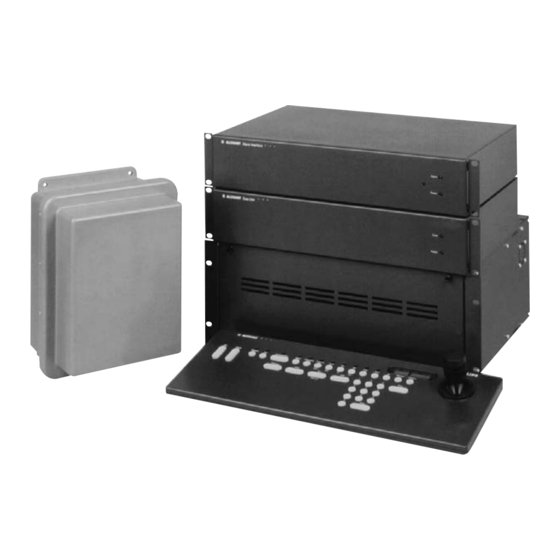
EN | 7 LTC 8540/00 Series | Instruction Manual | Unpacking UNPACKING DESCRIPTION Unpack carefully. This is electronic equipment and The LTC 8540/00 Alarm Interface Unit provides the should be handled with care. Allegiant® series of matrix switcher/controllers (LTC 8500, LTC 8600, TC8700, and LTC 8800) with... -
Page 8: Allegiant Cpu Bay Connections
EN | 8 LTC 8540/00 Series | Instruction Manual | Installation 4.2.2 Desk Top Mount 4.4 Operational Settings If the unit is not going to be rack mounted, the The unit contains internal DIP switches which can be enclosure’s mounting ears should be removed. The used to set certain operating characteristics. -
Page 9: Alarm Input Connections
EN | 9 LTC 8540/00 Series | Instruction Manual | Installation 4.5 Alarm Input Connections 2. Relay 1 will activate if the base Allegiant system is set to use the Sequence & Display alarm Connect any 2 conductor wire (shielded cable not... -
Page 10: Interface Port Pinouts
EN | 10 LTC 8540/00 Series | Instruction Manual | Installation Typically any 2 conductor wire can be used between the rear panel terminal block containing the unit relay outputs and the VCR alarm input. If some other external device is to be controlled, do not exceed the relay ratings of 10 W, 0.75 A. -
Page 11: Illustrations
EN | 11 LTC 8540/00 Series | Instruction Manual | Illustrations ILLUSTRATIONS SWITCH LTC 8540/00 Alarm Interface Unit Layout ALARM POWER Front RS232 A1 6 A2 4 12 V 12 V A1 5 A2 3 A1 4 A2 2 A1 3... - Page 12 Cette opération permet d'éviter les dégâts au d'origine. L'utilisation de pièces non homologuées niveau de l'appareil en cas d'orage ou de surtension présente un risque d'incendie, d'électrocution et des lignes électriques. d'autres dangers. Bosch Security Systems | December 13, 2007...
- Page 13 2. Chargement mécanique - Le montage de l'appareil en bâti doit être exempt de tout risque d'accident lié à un chargement mécanique irrégulier. Bosch Security Systems | December 13, 2007...
- Page 14 (FCC), peut s'avérer utile : « How to Identify and Resolve Radio-TV Interference Problems ». Cette brochure est disponible auprès du U.S. Government Printing Office, Washington, DC 20402, États-Unis, sous la référence n° 004-000-00345-4. Bosch Security Systems | December 13, 2007...
- Page 15 ILLUSTRATIONS .............20 Bosch Security Systems | December 13, 2007...
-
Page 16: Deballage
également de huit sorties à fermeture de relais plusieurs éléments sont manquants, veuillez en lorsque des conditions d’alarme se produisent. informer le représentant commercial ou le bureau d’assistance à la clientèle de Bosch Security Systems. INSTALLATION Le carton d’emballage d’origine constitue le meilleur 4. 1 Alimentation/Données... -
Page 17: Options De Montage
DIP. Les tables ci-dessous. suivantes contiennent un récapitulatif des réglages des interrupteurs DIP et des fonctions qui leur sont associées: S929A39AE Retrait du couvercle et des pattes pour châssis Bosch Security Systems | December 13, 2007... -
Page 18: Connexions D'entrée D'alarme
à partir du clavier. Indique un réglage d’usine par défaut sur les appareils dont le L’appui de la touche “Acknowledge” numéro de série est inférieur à 1500. (Acquittement) du clavier du système ne Bosch Security Systems | December 13, 2007... -
Page 19: Brochage Du Port D'interface
Masse des données vidéo correspondant à l’alarme suit le contact Masse des données Entrée 12 Vca ou 12 Vcc appliqué à l’appareil dans ce mode de réponse Entrée 12 Vca ou 12 Vcc d’alarme. Bosch Security Systems | December 13, 2007... -
Page 20: Illustrations
MAIN LOBBY DOOR 11 11 90 Output Alarm Relay Data Typical Alarm Input System Cameras Allegiant Series VIDEO CASSETTE RECORDER Switcher/Controller Main CPU Equipment Bay Security VCR S9405014AE System Keyboard Exemple type d’application de l’interface d’alarme LTC 8540/00 Bosch Security Systems | December 13, 2007... - Page 21 FR | 21 LTC 8540/00 Série | Instructions d’installation | Bosch Security Systems | December 13, 2007...
- Page 22 Gewitters oder wenn es über einen längeren Zeitraum führen. nicht verwendet wird, indem Sie den Stecker aus der Steckdose ziehen und die Verbindung zum Kabelsystem trennen. So kann das Gerät nicht durch einen Blitzeinschlag oder Überspannung beschädigt werden. Bosch Security Systems | December 13, 2007...
- Page 23 Anweisungen des Herstellers befolgt werden. Die maximale Betriebstemperatur für dieses Gerät sollte nicht überschritten werden. 2. Mechanische Belastung - Beim Aufbau des Geräts in einem Rack ist auf mögliche Gefahren durch ungleiche mechanische Belastung zu achten. Bosch Security Systems | December 13, 2007...
- Page 24 ABBILDUNGEN ............. .29 Bosch Security Systems | December 13, 2007...
-
Page 25: Auspacken
Allegiant-CPU-Hauptgerät angeschlossen ist. E-Mail: BoschCCTVparts@ca.slr.com Kanada Telefon: 514-738-2434 Fax: 514-738-8480 Europa, Naher Osten und Asien Tel.: +44 (0) 1495 274558 Fax: +44 (0) 1495 274280 E-Mail: rmahelpdesk@solectron.com Weitere Informationen finden Sie unter www.boschsecurity.com. Bosch Security Systems | December 13, 2007... -
Page 26: Einbauoptionen
Die folgende Tabelle listet die und dann die Befestigungsklammer entfernen. Ggf. Einstellungen der DIP-Schalter mit ihren zugehörigen die untere Abbildung zu Rate ziehen. Funktionen auf: S929A39AE Entfernen der Abdeckung und der Gestellbefestigungsklammern Bosch Security Systems | December 13, 2007... -
Page 27: Alarmeingangsanschlüsse
Drücken der Quittiertaste an der Systemtastatur wird Relais 1 nicht deaktiviert, da das Alarmvideo in diesem Modus dem an das Gerät angelegten Kontakt folgt. Relais 2 bis 8 werden in diesem Modus nicht verwendet. Bosch Security Systems | December 13, 2007... -
Page 28: Pinbelegung Des Schnittstellenports
Funktion wurde in der zugehörigen Alarmgruppe ausgewählt. Wenn die Option ‘Monitor’ in der Gruppentabelle auf ‘1’ gestellt wurde, spricht nur Relais 1 an, wenn an den Monitoren dieser Alarmgruppe ein Alarm vorliegt. Bosch Security Systems | December 13, 2007... -
Page 29: Abbildungen
MAIN LOBBY DOOR 11 11 90 Output Alarm Relay Data Typical Alarm Input System Cameras Allegiant Series VIDEO CASSETTE RECORDER Switcher/Controller Main CPU Equipment Bay Security VCR S9405014AE System Keyboard Typische Anwendung der LTC 8540/00 Alarmschnittstelle Bosch Security Systems | December 13, 2007... - Page 30 óptimas de funcionamiento. Bosch Security Systems | December 13, 2007...
- Page 31 2. Carga mecánica - el montaje del equipo en un soporte se debe realizar de tal manera que no se cree una situación de peligro debido a una carga mecánica inestable. Bosch Security Systems | December 13, 2007...
- Page 32 ILUSTRACIONES .............37 Bosch Security Systems | December 13, 2007...
-
Page 33: Desembalaje
Centro de Servicio de Bosch Security Systems, Inc. de forma remota a través de una fuente de más cercano para solicitar autorización para enviar el alimentación Clase 2 suministrada o una equivalente... -
Page 34: Opciones De Montaje
DIP consulte la tabla de la unidad LTC 8540/00 mostrada a continuación. Las tablas siguientes resumen los ajustes de los interruptores DIP y sus funciones asociadas: S929A39AE Desmontaje de la cubierta y las orejetas de estantería Bosch Security Systems | December 13, 2007... -
Page 35: Conexiones De Entrada De Alarma
1 ya que el vídeo de alarma sigue el contacto aplicado a la unidad en este modo de respuesta de alarma. Los relés 2-8 no se usan en este modo. Bosch Security Systems | December 13, 2007... -
Page 36: Configuraciones De Patillas De Conexión De Puerto De Interfaz
(VersAlarm Group Table) del paquete de software Master Control basado en PC contiene un grupo de alarmas en las que se incluyen los monitores 1-8 y se ha seleccionado la opción ‘Monitor’ en la columna Bosch Security Systems | December 13, 2007... -
Page 37: Ilustraciones
Output Alarm Relay Data Typical Alarm Input System Cameras Allegiant Series VIDEO CASSETTE RECORDER Switcher/Controller Main CPU Equipment Bay Security VCR S9405014AE System Keyboard Aplicación de interfaz de alarma de LTC 8540/00 típica Bosch Security Systems | December 13, 2007... - Page 38 NL | 38 LTC 8540/00 Series | Installatie-instructies | Belangrijke Veiligheidsvoorschriften Belangrijke Veiligheidsvoorschriften 9. Veiligheidscontrole - Vraag de onderhoudstechnicus na een onderhoudsbeurt of een reparatie veiligheidscontroles 1. Lees, volg en bewaar de voorschriften - Lees en volg uit te voeren om na te gaan of het apparaat correct alle veiligheids- en bedieningsvoorschriften voordat u het functioneert.
- Page 39 NL | 39 LTC 8540/00 Series | Installatie-instructies | Belangrijke Veiligheidsvoorschriften WAARSCHUWING: Voor Producten Die Binnenshuis apparaat is gevoelig voor statische Worden Gebruikt elektriciteit. Volg de juiste 1. Water en vocht - Gebruik het apparaat niet in de voorzorgsmaatregelen voor...
- Page 40 NL | 40 LTC 8540/00 Series | Installatie-instructies | Inhoudsopgave INHOUDSOPGAVE UITPAKKEN ..............41 SERVICE .
-
Page 41: Uitpakken
NL | 41 LTC 8540/00 Series | Installatie-instructies | Uitpakken UITPAKKEN BESCHRIJVING Pak alles voorzichtig uit. Dit is electro-mechanische De LTC 8540/00 alarm interface unit levert de apparatuur en moet voorzichtig behandeld worden. Allegiant® serie matrix switcher/controllers (LTC 8500, LTC 8600, TC8700, en LTC 8800) met de... -
Page 42: Allegiant Cpu Bay Verbindingen
NL | 42 LTC 8540/00 Series | Installatie-instructies | Installatie 4.2.2 Montage op bureau 4.4 Operationele instellingen Als het apparaat niet op een rek gemonteerd moet De unit bevat interne DIP-schakelaars die gebruikt worden, moeten de montage-ogen van de behuizing kunnen worden om bepaalde verwijderd worden. -
Page 43: Alarm Inputverbindingen
NL | 43 LTC 8540/00 Series | Installatie-instructies | Installatie LTC 8540/00 1. Relais 1 activeert als het basis Allegiant systeem ingesteld is om de Basic alarm response modus S101 - DIP-schakelaar nr. Baud te gebruiken en een alarm vindt plaats op een Rate systeemmonitor. -
Page 44: Interface Poort Pinouts
NL | 44 LTC 8540/00 Series | Installatie-instructies | Installatie 4. Indien het VersAlarm™ groepstabelscherm in het op de PC gebaseerde Master Control softwarepakket een alarmgroep bevat waarin monitoren 1 tot en met 8 zitten en de ‘monitor’ optie is geselecteerd in de ‘Relais Actie’ kolom,... -
Page 45: Illustraties
NL | 45 LTC 8540/00 Series | Installatie-instructies | Ilustraciones ILLUSTRATIES SWITCH LTC 8540/00 Layout alarm interface unit ALARM POWER Front RS232 A1 6 A2 4 12 V 12 V A1 5 A2 3 A1 4 A2 2 A1 3... - Page 46 Bosch Security Systems | December 13, 2007...
- Page 47 2. Carico meccanico - Il montaggio dell'apparecchiatura in un rack deve essere effettuato in modo tale da impedire che si venga a creare una condizione di rischio dovuta a una distribuzione non uniforme del carico meccanico. Bosch Security Systems | December 13, 2007...
- Page 48 ILLUSTRAZIONI .............53 Bosch Security Systems | December 13, 2007...
-
Page 49: Disimballo
Se mancano dei componenti, avvisare il Rappresentante INSTALLAZIONE Bosch Security Systems, Inc. o il Servizio Assistenza. 4. 1 Corrente/Dati La confezione d’imballo è il contenitore più sicuro per Viene fornito in dotazione un cavo d’interfaccia per... -
Page 50: Opzioni Di Montaggio
OFF per disabilitare il cicalino acustico. S929A39AE S101 - DIP Switch N. Funzione ON per abilitare RTS/CTS. Rimozione del coperchio e delle alette del rack OFF per disabilitare RTS/CTS. 1 Denota i valori di default impostati in fabbrica. Bosch Security Systems | December 13, 2007... -
Page 51: Collegamenti Di Ingresso Degli Allarmi
In questa opzionale di software Allegiant Master Control. modalità i relé da 2 a 8 non vengono usati. Bosch Security Systems | December 13, 2007... -
Page 52: Funzioni Circuitali Piedini Porta Interfaccia
Ingresso a 12 V c.a. o 12 V c.c. (o gli allarmi) visualizzati sul monitor. Premendo Ingresso a 12 V c.a. o 12 V c.c. il tasto “Acknowledge” sulla tastiera del sistema i Bosch Security Systems | December 13, 2007... -
Page 53: Illustrazioni
MAIN LOBBY DOOR 11 11 90 Output Alarm Relay Data Typical Alarm Input System Cameras Allegiant Series VIDEO CASSETTE RECORDER Switcher/Controller Main CPU Equipment Bay Security VCR S9405014AE System Keyboard Pannello anteriore e posteriore LTC 8540/00 Bosch Security Systems | December 13, 2007... - Page 54 IT | 54 Serie LTC 8540/00 | Istruzioni per l’installazione | Bosch Security Systems | December 13, 2007...
- Page 55 IT | 55 Serie LTC 8540/00 | Istruzioni per l’installazione | Bosch Security Systems | December 13, 2007...
- Page 56 Singapore 577180 Tel: 800-326-3270 The Netherlands Republic of Singapore Fax: 1-717-735-6560 Tele +31 40 27 80000 Tel: 65 (6) 319 3486 www.boschsecuritysystems.com © 2007 Bosch Security Systems, Inc. F01U078186 07-51 | December 13, 2007 | Data subject to change without notice.