
Related Manuals for New Holland BNAC930HB


Summary of Contents for New Holland BNAC930HB
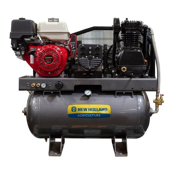
- Page 1 30 GALLON AIR BNAC930HB BNAC1330HEB2 BNAC1330HG2 BNAC1330HGW user manual 85.610.360...
-
Page 2: Table Of Contents
tAbLe Of cONteNts Introduction 4 Using the Operators Manual Specifications 4 Specifications Product Identification 5 Record Identification Numbers Safety 6 Safety Instructions 7 Safety Rules 7 Hazard Symbols and Meanings 10 General Safety Information Safety & Installation 11 Spraying Precautions 11 Hose Precautions 11 Installation and Location 11 Extension Cords Generator Safety 12 Generator Safety 13 Grounding Instructions Assembly Instructions 14 Assembly Product Features 15 Automatic ON/OFF 15 Regulator 15 Tank Pressure Gauge 15 Safety Valve 15 Tank Drain Fitting 15 Safety Guard... - Page 3 tAbLe Of cONteNts Operating Instructions 16 Initial Start Up 16 Start Up 16 Storage 16 Shut Down Maintenance 17 Daily 17 Weekly 17 Monthly 17 Six Months or 250 Operating Hours 17 Oil Change Troubleshooting 18 Compressor 19 Generator Components 20 Diagram 21 List Warranty 22 Warranty Statement...
-
Page 4: Introduction
Using the Operator’s manual Thank you for choosing our compressor. The manual gives information regarding operation and maintenance of the Compressor. Be sure to read it carefully before operation. Following the manual can ensure the user’s safety and the best results from the compressor. All information and diagrams in this manual are in accordance with the newest products at the publishing time. We strive for accuracy and this manual is accurate for the models described at the time of printing. We reserve the right to make improvements or changes at any time without notice or obligation. Please keep this manual with the compressor at all times, even if ownership of the compressor is transferred to someone else. Model # BNAC930HB BNAC1330HEB2 BNAC1330HG2 BNAC1330HGW Engine Honda GX270 Honda GX390 Honda GX390 Honda GX390 Watts (Comp. Off) 4000W 5500W Watts (Comp. On) 3500W... -
Page 5: Product Identification
pROduct IdeNtIfIcAtION Record Identification Numbers COMPRESSOR/GENERATOR If you need to contact an Authorized Dealer or Customer Service line (1-855-850-6668) for information or servicing, always provide the product model and identification numbers. You will need to locate the model and serial number for the machine and record the information in the spaces provided below. Date of Purchase: Dealer Name: Dealer Phone: Product Identification Numbers Model Number: Serial Number:... -
Page 6: Safety
sAfety Safety Instructions 1. Carefully read through the entire owners manual before operating this compressor to ensure all safety precautions are adhered to. 2. After unpacking your new air compressor, please inspect it carefully for any damage that may have occurred during transit. 3. Do not operate this air compressor if damaged during shipment, handling, or misuse. 4. Damage may result in bursting, which can cause serious injury or property damage. 5. All damaged parts must be repaired or replaced as needed prior ton operating this air compressor. 6. Check to see that all nuts, bolts and fittings are secure. 7. Check to see that the engine oil level is within an acceptable range. If it is too low, refer to the engine user manual for instruction on how to add or change oil. 8. Inspect hoses and cords to ensure that they are unfrayed and in good condition. 9. Please contact our customer service department at the numbers listed on the back of this instruction manual for any questions or comments regarding this air compressor. -
Page 7: Safety Rules
sAfety Save these Instructions SAFETY RULES This is the safety alert symbol. It is used to alert you to potential personal injury hazards. Obey all safety messages that follow this symbol to avoid possible injury or death. The safety alert symbol ( ) is used with a signal word (DANGER, CAUTION, WARNING), a pictorial and/or a safety message to alert you to hazards. DANGER indicates a hazard which, if not avoided, will result in death ... - Page 8 sAfety WARNING AIR TANK WARNING: Drain liquid from air tank daily, or after each use, using the drain valve located on the bottom of the lower air tank. Failure to properly drain liquid from the tank will cause rust from moisture buildup. This weakens the tank and could lead to a violent tank explosion, Periodically inspect the tanks for unsafe conditions such as corrosion. Never attempt to repair or make modifications to the tank or its attachments. Welding, drilling, or any other modifications may weaken the tank, which may result in damage from rupture or explosion. Never remove or attempt to adjust the pressure switch, safety valve, or other factory set operating pressures. WARNING FIRE WARNING: Avoid dangerous environments. Do not use the compressor near gasoline or other flammable materials. Keep work area well lit. Normal sparking of a motor or sparking from grinding metal could ignite fumes. Do not spray flammable materials in the vicinity of an open flame or other ignition source, including the air compressor itself. Do not direct paint or other spray material towards the compressor. Read and follow all safely instructions for the material you are spraying. Be sure to use an approved respirator designed for use with your specific application. WARNING BREATHABLE AIR WARNING: This air compressor is not designed, nor intended to produce breathable air. Air produced by this unit may contain carbon monoxide or other toxic vapors. Do not inhale air from the compressor or from a breathing device connected to it. ...
- Page 9 sAfety WARNING AIR TOOLS AND ACCESSORIES WARNING: Do not exceed the pressure rating of any air tools, spray guns, air accessories, or inflatables. Excess pressure can cause them to explode, resulting in serious injury. Follow the manufacturers recommended pressure settings for all air tools and air accessories. WARNING Do not direct compressed air stream at people or pets. The powerful compressed air stream can damage exposed skin and easily propel loose dirt or other small objects. Always wear eye protection that meets ANSI Z28.1 specifications. WARNING Keep hands and fingers away from exposed metal parts on a running air compressor. Air compressors generate significant heat during normal operation, which can cause serious burns. The compressor will remain hot for some time after operation and should not be touched or moved until cool.
-
Page 10: General Safety Information
sAfety GENERAL SAFETY INFORMATION Do not operate unit if damaged during shipping, handling or use. Damage may result in bursting and cause injury or property damage. Since the air compressor and other components (filters, lubricators, hoses, etc.) used, make up a high pressure pumping system, the following safety precautions must be observed at all times: 1. Read all manuals included with this product carefully. Be thoroughly familiar with the controls and the proper use of the equipment. 2. Follow all local electrical and safety codes 3. Only persons well acquainted with these rules of safe operation should be allowed to use the compressor. 4. Keep visitors away and do not allow children in the work area. 5. Wear safety glasses and use hearing protection when operating the pump or unit. 6. Do not stand on or use any part of the unit as a handhold. 7. Before each use, inspect the compressor system and electrical components for signs of damage, deterioration, weakness, or leakage. Repair or replace defective items before using. 8. Check all fasteners at frequent intervals and tighten if needed. 9. Keep fingers away from a running compressor; fast moving and hot parts will cause injury and/or burns. 10. If the equipment starts to vibrate in an abnormal manner, STOP the engine/motor and check immediately for the cause. Vibration is generally a warning of trouble. 11. To reduce the risk of fire, keep engine/motor exterior free of oil, solvent, or excessive grease. Never remove or attempt to adjust safety valve. Keep safety valve free from paint and other ... -
Page 11: Spraying Precautions
sAfety SPRAYING PRECAUTIONS 17. Do not smoke when spraying paint, insecticides, or other flammable substances. 18. Use a face mask/respirator when spraying and spray in a well ventilated area to prevent health and fire hazards. 19. Do not direct paint or other sprayed material at the compressor. Locate compressor as far away from the spraying area as possible to minimize overspray accumulation on the compressor. 20. When spraying or cleaning with solvents or toxic chemicals, follow the instructions provided by the chemical manufacturer. WARNING Do not spray flammable materials in vicinity of open flame or near ignition sources including the compressor unit. HOSE PRECAUTIONS 21. Inspect hose before use. Do not exceed working pressure marked on hose. Do not twist, bend knot, or abrade hose. Do not wrap hose around body. 22. Keep away from hot surfaces and chemicals. Installation INSTALLATION AND LOCATION The compressor must be used on a stable level surface. The air compres- sor must be used in a clean and well-ventilated area. The compressor requires an unobstructed airflow and must be located a minimum of 18 inches from any walls or other obstructions. Extension Cord Length Wire Size (A.W.C.) Up to 25 Feet 26 to 50 Feet 51 to 100 Feet... -
Page 12: Generator Safety
GeNeRAtOR sAfety This unit is equipped with a grounding terminal for your protection. Always complete the ground path from the unit to an external ground source as instructed in the following page. The unit is a potential source of electrical shock if not kept dry. Keep the unit dry and do not use in rain or wet conditions. To protect from moisture, operate it on a dry surface under an open, canopy-like structure. Dry your hands if wet before touching the unit. Plug appliances directly into the unit. Or, use a heavy duty, outdoor-rated extension cord that is rated (in watts or amps) at least equal to the sum of the connected appliance loads. Check that the entire cord is free of cuts or tears and that the plug has all three prongs, especially a grounding pin. NEVER try to power house wiring by plugging the unit into a wall outlet, a practice known as “back feeding”. This is an extremely dangerous practice that presents an electrocution risk to utility workers and neighbors served by the same utility transformer. It also bypasses some of the built-in household circuit protection devices. If you must connect the unit to the house wiring to power appliances, have a qualified electrician install the appropriate equipment in accordance with local electrical codes. Or, check with your utility company to see if it can install an appropriate power transfer switch. For power outages, permanently installed stationary units are better suited for providing backup power to the home. Even a properly connected portable unit can become overloaded. This may result in overheating or stressing the unit components, possibly leading to a unit failure. -
Page 13: Grounding Instructions
GROuNdING INstRuctIONs This product must be grounded. Should a malfunction occur, grounding provides the path of least resistance for the electric current, reducing the rish of electrocution. The screw and ground terminal on the frame must always be used to connect the unit to a suitable ground source. The ground path should be made with #8 size wire. Connect the terminal of the ground wire between the star washers and screw then tighten the screw fully. Connect the other end of the wire securely to a suitable ground source. The National Electric Code contains several practical ways in which to establish a good ground source. Examples given below illustrate a few of the ways in which a good ground source may be established. A metal underground water pipe in direct contact with the earth for at least 10 feet can be used as a grounding source. If a pipe is unavailable, an 8 foot length of pipe or rod may be used as the ground source. The pipe should be 3/4 inch trade size or larger and the outer surface must be noncorrosive. If a steel or iron rod is used it should be at least 5/8 inch diameter and if a nonferrous rod is used it should be at least 1/2 inch diameter and be listed as material for ... -
Page 14: Assembly Instructions
AssembLy INstRuctIONs Assembly Read all safety instructions before using air compressor. WARNING The compressor is shipped without oil in the crankcase. Add oil as indicated below. Oil Level OK Check Oil Level Daily Refill Oil Immediately 1. After opening the carton, please remove all parts and check against photograph on carton. If any parts are missing, please call 1-855- 850-6668. 2. Place air compressor on a flat, level surface. 3. Pour supplied oil into crankcase until the oil level reaches the red dot in the oil level sight glass. Be careful not to overfill. 1/2” 4. Adjust tension of belt to ensure that a maximum of 1/2” / 12mm of slack exists when pressure is placed on belt at centre line. NOTE: If the belt is too tight, overloading of the motor will occur. This will cause the motor to overheat. If the belt is installed too loose, it will slip and unstable operation and vibration will occur. Caution - The rotating direction for the flywheel must follow the arrow shown on the belt guard. 5. Close the tank drain valve on the bottom of the air tank by turning the valve clockwise until it’s fully closed. 6. Attach the air coupler to the compressor regulator valve. Use Teflon thread-sealing tape on the threads to make sure you have an airtight connection. Do not over tighten fittings. 7. ... -
Page 15: Product Features
pROduct feAtuRes Product Features 1. Automatic ON/OFF Pressure Switch The compressor is equipped with an automatic on/off pressure switch. The compressor will only run when the switch is in the “I”(ON) position. Once the tank has reached the desired preset pressure (see Operation Instructions), the pump will automatically shut off. While the switch is in the “I”(ON) position, the pump will automatically turn back on once the pressure in the tank drops below the minimum preset pressure. Do not leave the compressor unattended while the power switch is in the “I”(ON) position. 2. Regulator The regulator allows you to select the amount of air pressure that is output through the air hose into tools and accessories. Refer to the air delivery requirements of your tools for the proper pressure settings. 3. Tank Pressure Gauge The tank pressure gauge provides a reading of the air pressure inside of the compressor tank. 4. Safety Valve This compressor is equipped with a safely valve switch that will engage when the pressure in the tank exceeds the maximum rated pressure. DO NOT attempt to modify or remove safely valve. 5. Tank Drain Fitting Water is produced whenever air is compressed. It is critical to drain water from the air tank on this compressor frequently. If unit is used only occasionally, tank should be drained after each use and prior to ... -
Page 16: Operating Instructions
OpeRAtION Operating Instructions Initial Start Up 1. Disconnect tools and/or accessories from the air hose and generator power outlets (if applicable). 2. Open the tank drain valve to allow air to escape. This helps prevent air pressure buildup in the air tank. 3. Check to see that the belt is installed properly with the correct tension. 4. Flip the pilot valve to the upright position. This provides a loadless start. 5. Run the compressor for at least 2 minutes in this no-load position to lubricate the bearings and piston. 6. Turn off compressor, drain liquid from tanks and close drain valve. Start Up 1. Slowly open tank drain by turning clockwise. Allow any water in tank to drain out. Close fitting securely. 2. Before starting the compressor, check for broken components and accessories, and check for damage to the hose. 3. Make sure the power switch on the engine is turned to the “O”(OFF) position. 4. Attach desired tool to the end of the air hose and plug in any items you wish to power to the generator 5. Turn the ON/OFF switch to the “I”(ON) position. 6. Adjust regulator knob to desired pressure level once the pump has shut off and the compressor has stopped running. Storage 1. ... -
Page 17: Maintenance
mAINteNANce Maintenance When performing any maintenance or service · The air compressor must be turned off. · Drain tanks. · Allow compressor to cool down. · Disconnect all air hoses and unplug all items from the generator. Daily · Check oil level. · Drain accumulated liquid from tanks. · Check for oil leaks. · Check for unusual noise and/or vibrations · Check that all fasteners are secure. Weekly · Check safety relief valve. ... -
Page 18: Troubleshooting
tROubLeshOOtING Compressor Problem Possible Cause Solutions Compressor 1. Drive engine low on fuel. 1. Check fuel level in drive engine. stalls and dies 2. Compressor check valve not 2. Inspect compressor check functioning. valve. 3. Compressor Pilot valve not 3. Check drive engine spark plug. functioning. 4. Check oil level on compressor 4. Spark Plug in engine is bad. drive engine. 5. Drive engine low on oil. 5. Check oil on compressor pump. Compressor 1. Compressor pilot valve is 1. Check pilot valve to make sure is running but actuated. it is in the proper position. is not 2. Compressor pilot valve is 2. Replace compressor pilot valve. compressing malfunctioning. 3. Check and clean compressor 3. Compressor pump head pump head unloaders. unloaders stuck engaged. Compressor 1. Throttle control valve (bullwhip) 1. Check throttle control valve does not idle ... -
Page 19: Generator
tROubLeshOOtING Compressor 1. Bad check valve. 1. Use IS 100 (30W) compressor won’t start in 2. Compressor has the wrong oil for cold weather conditions. cold weather grade of oil. 2. Move compressor to a warmer- 3. Control lines frozen. location. 3. Put a heat lamp on compres- sor to maintain above freezing temperatures. Compressor 1. Compressor is not properly 1. Properly mount compressor on is vibrating mounted on vibration isolation vibration isolation pads. excessively pads. 2. Compressor pulley is out of 2. Re-align pulleys. alignment. 3. Engine is low on fuel of throttle 3. Check drive engine oil and fuel is out of adjustment. level. 4. Re-adjust engine throttle con- trol (bull whip). Generator Problem Possible Cause Corrective Action Low Voltage Engine Speed is too low Replace or repair engine throttle Generator is overloaded Reduce load on generator by ... - Page 20 cOmpONeNts Please Note: The following diagram is intended for general reference of your compressor. Your unit may differ slightly from the unit shown below. 9 10 11 12 13 BNAC1330HG2 & BNAC1330HGW feature a generator located between the air pump and the engine. See the generator manual included with these compressors for more information. ...
- Page 21 cOmpONeNts REF # Description Manual Tank Drain 30 Gallon 200 PSI Tank Tank Discharge Port Pilot Valve (Pressure Control) Pressure Gauge Throttle Control (Bull Whip) Drive Engine Drive Engine Pulley Drive Engine Pulley Mounting Hub Reciprocating Compressor Drive Belt Reciprocating Pump Discharge Line 250 PSI Discharge Safety Valve Reciprocating Pump Discharge Fitting Reciprocating Pump Air Filter Element & Housing Belt Guard Reciprocating Compressor Pump Inner Stage 70 PSI Safety Valve Centrifugal Unloader Oil Sight Glass Oil Drain Tube Reciprocating Pump Mounting Bolts Tank Safety Valve 200 PSI Tank Check Valve...
-
Page 22: Warranty
WARRANTY CALIFORNIA AND FEDERAL EXHAUST AND EVAPORATIVE EMISSIONS CONTROL WARRANTY STATEMENT YOUR WARRANTY RIGHTS AND OBLIGATIONS The California Air Resources Board, the United States Environmental Protection Agency and Chongqing Rato Technology Co., Ltd. (Rato), are pleased to xplain the exhaust and evaporative emissions (“emissions”) control system warranty on your 2019/2020 small off-road engine/equipment. - Page 23 WARRANTY distribution center or service center as soon as the problem exists. The warranty repairs shall be completed in a reasonable amount of time, not to exceed 30 days. If you have any questions regarding your warranty rights and responsibilities, you should contact BE POWER EQUIPMENT at 1-800-663-8331 (free phone) or Email at info@bepressure.com DEFECTS WARRANTY REQUIREMENTS...
- Page 24 WARRANTY 1. Notwithstanding the provisions of Subsection (4) above, warranty services or repairs must be provided at distribution centers that are franchised to service the subject engine/equipment. 2. The owner must not be charged for diagnostic labor that leads to the determination that a warranted part is in fact defective, provided that such diagnostic work is performed at a warranty station.
- Page 25 WARRANTY • Valves affecting distribution of flow. • Distribution manifold. 6. Catalyst or Thermal Reactor System • Catalytic converter. • Thermal reactor. • Exhaust manifold. 7. Particulate Controls • Traps, filters, precipitators, and any other device used to capture particulate emissions.
- Page 26 If you need assistance with the assembly or operation of this Compressor please call 1-855-850-6668...