Table of Contents
Advertisement
Quick Links
Advertisement
Table of Contents

Related Manuals for New Holland BNAC658HB


Summary of Contents for New Holland BNAC658HB
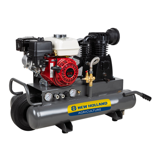
- Page 1 WHEELED AIR COMPRESSOR BNAC658HB BNAC708RB BNAC908HB operation manual...
-
Page 2: Table Of Contents
table of contents Introduction Using the Operators Manual Specifications Specifications Product Identification Record Identification Numbers Safety Safety Instructions Safety Rules Hazard Symbols and Meanings 10 General Safety Information Safety & Installation 11 Spraying Precautions 11 Hose Precautions 11 Installation and Location 11 Extension Cords Assembly Instructions 12 Assembly... - Page 3 table of contents Operating Instructions 14 Initial Start Up 14 Start Up 14 Storage 14 Shut Down Maintenance 15 When performing any maintenance or service 15 Daily 15 Weekly 15 Monthly 15 Six Months or 250 Operating Hours 15 Oil Change Troubleshooting 16 Troubleshooting Chart Parts...
-
Page 4: Introduction
introduction Attention: Read through the complete manual prior to the initial use of your compressor. Using the Operator’s manual Thank you for choosing our compressor. The manual gives information with respect to operation and maintenance of the Compressor and be sure to read it carefully first before operation. -
Page 5: Product Identification
product identification Record Identification Numbers COMPRESSOR If you need to contact an Authorized Dealer or Customer Service line for information on servicing, always provide the product model and identification numbers. You will need to locate the model and serial number for the machine and record the information in the places provided below. -
Page 6: Safety
safety Safety Instructions · Carefully read through the entire owners manual before operating this compressor. · Keep manual with important records for safety instructions, operating procedures and warranty. · After unpacking your new air compressor, please inspect it carefully for any damage that may have occurred during transit. -
Page 7: Safety Rules
safety Save these Instructions SAFETY RULES This is the safety alert symbol. It is used to alert you to potential personal injury hazards. Obey all safety messages that follow this symbol to avoid possible injury or death. The safety alert symbol ( ) is used with a signal word (DANGER, CAUTION, WARNING), a pictorial and/or a safety message to alert you to hazards. - Page 8 safety WARNING AIR TANK WARNING: Drain liquid from air tank daily, or after each use, using the drain valve located on the bottom of the lower air tank. Failure to properly drain liquid from the tank will cause rust from moisture build- up, which weakens the tank and could lead to a violent tank explosion, Periodically inspect the tanks for unsafe conditions such as corrosion.
- Page 9 safety WARNING AIR TOOLS AND ACCESSORIES WARNING: Do not exceed the pressure rating of any air tools, spray guns, air accessories, or inflatables. Excess pressure can cause them to explode, resulting in serious injury. Follow the manufacturers recommended pressure set- tings for all air tools and air accessories.
-
Page 10: General Safety Information
safety GENERAL SAFETY INFORMATION Do not operate unit if damaged during shipping, handling or use. Damage may result in bursting and cause injury or property damage. Since the air compressor and other components (filters, lubricators, hoses, etc.) used, make up a high pressure pumping system, the following safety precautions must be observed at all times: Read all manuals included with this product carefully. -
Page 11: Safety & Installation
& safety installation SPRAYING PRECAUTIONS 15. Do not smoke when spraying paint, insecticides, or other flammable substances. 16. Use a face mask/respirator when spraying and spray in a well ventilated area to prevent health and fire hazards. 17. Do not direct paint or other sprayed material at the compressor. Locate compressor as far away from the spraying area as possible to minimize overspray accumulation on the compressor. -
Page 12: Assembly Instructions
assembly instructions Assembly Read all safety instructions before using air compressor. WARNING The compressor is shipped without oil in the crankcase. Add oil as indicated below. Oil Level OK Check Oil Level Daily Refill Oil Immediately After opening the carton, please remove all parts and check against photograph on carton. -
Page 13: Product Features
product features Product Features 1. Automatic ON/OFF Pressure Switch The compressor is equipped with an automatic on/off pressure switch. The compressor will only run when the switch is in the “I”(ON) position. Once the tank has reached the desired preset pressure (see Operation Instructions), the pump will automatically shut off. -
Page 14: Operating Instructions
operation Operating Instructions Initial Start Up Disconnect tools and/or accessories from the air hose. Open the tank drain valve to allow air to escape preventing air pressure buildup in the air tank. Check to see that the belt is installed properly with the correct tension. Plug power supply cord into proper power source receptacle. -
Page 15: Maintenance
maintenance Maintenance When performing any maintenance or service · The air compressor must be turned off. · Drain tanks. · Allow compressor to cool down. Daily · Check oil level. · Drain accumulated liquid from tanks. · Check for oil leaks. ·... -
Page 16: Troubleshooting
troubleshooting Troubleshooting Chart Trouble Possible Cause Corrective Action No start condition Gas engine not running Check operation of gas engine Low pressure Air leak in safety valve Check valve manually by pulling upward on rings. If condition persists, replace valve. Loose tube or fittings Tighten fittings Restricted air filter... -
Page 17: Parts
BNAC708RB/BNAC658HB Parts Diagram REF. DESCRIPTION PART # Exhaust Pipe Assembly 42.004.020 Safety Guard 42.008.013 V-Belt 42.004.021 Motor Pulley 42.004.029 Pump 42.004.022 Discharge tubing 42.004.023 Six Angle Nut 42.004.024 Manifold 42.004.011 Pressure Gauge 42.004.031 Safety valve 42.006.009 Drain Cock 42.004.025 Pilot Unloader Valve 42.004.026... - Page 18 parts BNAC908HB Parts Diagram REF. DESCRIPTION PART # Exhaust Pipe Assembly 42.004.019 Motor Pulley 42.008.015 Pump 42.008.007 Manifold 42.004.011 Pipe 42.008.000 Screw, 42.008.005 Tank Wheel Six Angle Nut V-Belt 42.008.006 Bolt Washer Safety Guard Seat L Safety Guard M5x0.8x8 Screw 42.008.016 Safety Guard Safety Guard Seat S...
- Page 19 BNAC708RB/BNAC658HB pump Parts Diagram...
- Page 20 parts Parts List NO. DESCRIPTION PART # NO. DESCRIPTION PART # Bolt Stud Spring Washer Cylinder Cylinder Head Gasket, Cylinder Air Filter Assy 42.004.028 Breather Assy 42.004.030 Front Cover, Air Filter 41a Breather Element, Air Filter 41b Washer,Breather Rear Cover, Air Filter Ball Exht.
- Page 21 parts BNAC908HB Pump Parts Diagram...
- Page 22 parts Parts List NO. DESCRIPTION PART # NO. DESCRIPTION PART # Breather Safety Valve 42.008.004 Washer, Breather In-Six Angle Bolt Bearing Cover Spring Washer Spring Washer Exhuast Cooler 42.008.019 In-Six Angle Bolt In-Six Angle Bolt Oil Leveler Flange 42.008.003 Washer, Oil Leveler Nipple Oil Drain Plug Air Filter Assy...
- Page 23 WARRANTY CALIFORNIA AND FEDERAL EXHAUST AND EVAPORATIVE EMISSIONS CONTROL WARRANTY STATEMENT YOUR WARRANTY RIGHTS AND OBLIGATIONS The California Air Resources Board, the United States Environmental Protection Agency and Chongqing Rato Technology Co., Ltd. (Rato), are pleased to xplain the exhaust and evaporative emissions (“emissions”) control system warranty on your 2019/2020 small off-road engine/equipment.
- Page 24 WARRANTY distribution center or service center as soon as the problem exists. The warranty repairs shall be completed in a reasonable amount of time, not to exceed 30 days. If you have any questions regarding your warranty rights and responsibilities, you should contact BE POWER EQUIPMENT at 1-800-663-8331 (free phone) or Email at info@bepressure.com DEFECTS WARRANTY REQUIREMENTS...
- Page 25 WARRANTY 1. Notwithstanding the provisions of Subsection (4) above, warranty services or repairs must be provided at distribution centers that are franchised to service the subject engine/equipment. 2. The owner must not be charged for diagnostic labor that leads to the determination that a warranted part is in fact defective, provided that such diagnostic work is performed at a warranty station.
- Page 26 WARRANTY • Valves affecting distribution of flow. • Distribution manifold. 6. Catalyst or Thermal Reactor System • Catalytic converter. • Thermal reactor. • Exhaust manifold. 7. Particulate Controls • Traps, filters, precipitators, and any other device used to capture particulate emissions.
- Page 27 NOTES...
- Page 28 If you need assistance with the assembly or operation of this Compressor please call 1-855-850-6668...