Table of Contents
Advertisement
Quick Links
SERVICE
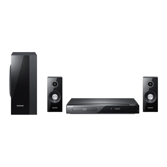
2.1CH Blu-ray Home Theater System
HT-C5200
Refer to the service manual in the GSPN (see the rear cover) for the more information.
2.1CH Blu-ray
Home Theater System
Model Name : HT-C5200
Model Code : HT-C5200/EDC
Speaker
PS-C5200
Front
PS-FC5200
Subwoofer
PS-WC5200
Manual
1. Precaution
2. Product Specification
3. Disassembly & Reassembly
4. Troubleshooting
5. Exploded View & Part List
6. PCB Diagram
7. Schematic Diagram
CONTENTS
Advertisement
Table of Contents

Related Manuals for Samsung HT-C5200/EDC


Summary of Contents for Samsung HT-C5200/EDC
- Page 1 2.1CH Blu-ray Home Theater System Model Name : HT-C5200 Model Code : HT-C5200/EDC Speaker PS-C5200 Front PS-FC5200 Subwoofer PS-WC5200 SERVICE Manual 2.1CH Blu-ray Home Theater System CONTENTS 1. Precaution 2. Product Specification 3. Disassembly & Reassembly 4. Troubleshooting 5. Exploded View & Part List 6.
- Page 2 Asia asia.samsungportal.com Mideast & Africa mea.samsungportal.com © Samsung Electronics Co.,Ltd. Apr. 2010 This Service Manual is a property of Samsung Electronics Printed in Korea Co.,Ltd. Any unauthorized use of Manual can be punished under applicable International and/or domestic law.
-
Page 3: Table Of Contents
Contents 1. Precaution 1-1 Safety Precautions ................... 1-1 1-2 Servicing Precautions ..................1-3 1-3 Precautions for Electrostatically Sensitive Devices (ESDs) ......1-4 2. Product Specification 2-1 Product Feature ....................2-1 2-2 Specifications ....................2-2 2-3 Specifications Analysis ..................2-6 2-4 Accessories ......................2-9 3. Disassembly & Reassembly 3-1 Overall Disassembly &... - Page 4 Contents 7. Schematic Diagram 7-1 Overall Block Diagram ..................7-1 7-2 FRONT ......................7-2 7-3 KEY ........................7-3 7-4 AMP-1 ......................7-4 7-5 AMP-2 ......................7-5 7-6 AMP-3 ......................7-6 7-7 AMP-4 ......................7-7 7-8 ETHERNET / USB / WI-FI ................7-8 7-9 VIDEO / IPOD VIDEO ..................7-9 7-10 HDMI MICOM....................7-10 7-11 HDMI RX ......................7-11 7-12 HDMI TX ......................7-12...
-
Page 5: Precaution
1 and 5.2 megohms. If there is no return path, the measured resistance should be “infinite.” If the resistance is outside these limits, a shock hazard might exist. See Fig. 1-2 Samsung Electronics... - Page 6 . Use replacement components that have the same ratings, especially for flame resistance and dielectric strength specifications. A replacement part that does not have the same safety characteristics as the original might create shock, fire or other hazards. Samsung Electronics...
-
Page 7: Servicing Precautions
8. Always connect a test instrument’s ground lead to the instrument chassis ground before connecting the positive lead; always remove the instrument’s ground lead last. First read the “Safety Precautions” section of this manual. If some unforeseen circumstance creates a conflict between the servicing and safety precautions, always follow the safety precautions. Samsung Electronics... -
Page 8: Precautions For Electrostatically Sensitive Devices (Esds)
8. Minimize body motions when handling unpackaged replacement ESDs. Motions such as brushing clothes together, or lifting a foot from a carpeted floor can generate enough static electricity to damage an ESD. Samsung Electronics... -
Page 9: Product Specification
- i-POD Docking, supporting i-POD/iPod - Various Video Setups • Progressive Mode • Still Mode • BD Wise • Picture Control HT-BD1250 → HT-C5200 - DLNA, WIDGET - MKV, MP4 - Under 0.3W Stand-by Power Consumption Energy-Star. - Variable Power / Intelligence Power Samsung Electronics... -
Page 10: Specifications
Y: 1.0 Vp-p (75Ω load) VIDEO OUTPUT Pr: 0.70 Vp-p (75Ω load) Component Video Pb: 0.70 Vp-p (75Ω load) Blu-ray Disc: 1080i, 720p, 576p(480p), 576i(480i) DVD: 576p(480p), 576i(480i) VIDEO/ 1080p, 1080i, 720p, 576p(480p) HDMI AUDIO PCM multichannel audio, Bitstream audio, PCM audio Samsung Electronics... - Page 11 140Hz ~ 20KHz 40Hz ~ 160Hz Output sound pressure level 87dB/W/M 88dB/W/M SPEAKER Rated input 165W 170W Maximum input 330W 340W Front: 90 x 207.5 x 68.5 mm Dimensions (W x H x D) Subwoofer: 168 x 350 x 295 mm Weights Front: 0.67 kg, Subwoofer: 3.80 kg Samsung Electronics...
- Page 12 Max Resolution Auto which TV can 480i Cannot select 480i support 1080P@60F 1080P@60F 480i Cannot select 480i 1080i 1080i 480i 480P 480i 720P 720P 480i 480P 480i 480P 480P 480i 480P 480i 480i Cannot select Cannot select 480i 480i Samsung Electronics...
- Page 13 Max Resolution Auto which TV can 576i Can select 576i support 1080P@60F 1080p@50F 576i Can select 576i 1080i 1080i@25F 576i 576p 576i 720P 720p@50F 576i 576p 576i 576P/480P 576p@50F 576i 576p 576i 576i/480i Can select Can select 576i 576i Samsung Electronics...
-
Page 14: Specifications Analysis
(Progressive Mode, Picture Quality (Progressive Mode, (Progressive Mode, Still Mode, BD Wise, control Still Mode, BD Wise, Still Mode, BD Wise, Picture Control, Picture Control) Picture Control) Sharpness, Movie) : Feature Included, X: Not Included Samsung Electronics... - Page 15 Re-encoding (intoDTS) (into DTS) (into DTS) DTS-HD MA Essential DTS-HD MA Essential DTS-HD MA Essential HD audio bit dts-HD HRA dts-HD HRA dts-HD HRA stream output on TrueHD TrueHD TrueHD HDMI 1.3 : Feature Included, X: Not Included Samsung Electronics...
- Page 16 One Board Main ↔ Loader (BCM 7630 - Back end, (BCM 7601 - Back end, (BCM 7440 - Back end, SoC chip - Front end) BCM7620 - Front end) BCM7620 - Front end) : Feature Included, X: Not Included Samsung Electronics...
-
Page 17: Accessories
Product Specification 2-4 Accessories 2-4-1 Supplied Accessories Accessories Item Item code Remark Remote Control AH59-02303A Battery 4301-001035 iPod Dock AH96-00051A Video Cable AH39-40001V Local Samsung Dealer FM Antenna AH42-00021A User’s Manual AH68-02257F Samsung Electronics... - Page 18 MEMO 2-10 Samsung Electronics...
-
Page 19: Disassembly & Reassembly
IC chips on the PCB are vulnerable to static electricity. - In order to assemble reverse the order of disassembly. Description Description Photo 1) Unfasten 5 screws on the DECO-SIDE. 2) Remove DECO-SIDE & TOP on the direction of Rear. 1) Unfasten 1 screw to remove CABINET-FRONT. Samsung Electronics... - Page 20 Disassembly & Reassembly Description Description Photo 2) Loosen hooks from CABINET-BOTTOM. 3) Disconnect wire, then remove the CABINET-BOTTOM. 1) Unfasten 1 screw, then remove ASSY PCB FRONT. Samsung Electronics...
- Page 21 Disassembly & Reassembly Description Description Photo 1) Unfasten 4 screws, disconnect FPC wire, and remove ASSY-DECK. 1) Unfasten 2 screws, then remove BRACKET-TOP. 2) Unfasten 3 screws, loosen 1 hook, and disconnect 2 wires and remove ASSY-SMPS and POWER- CORD. Samsung Electronics...
- Page 22 Disassembly & Reassembly Description Description Photo 1) Unfasten 2 screws and 1 wire, then remove ASSY PCB MAIN. 1) Unfasten 5 screws to remove AMP and FAN. Samsung Electronics...
- Page 23 Disassembly & Reassembly Description Description Photo 1) Remove ASSY PCB AMP and FAN. Samsung Electronics...
-
Page 24: Deck Disassembly & Reassembly
2. Push 4 Hooks 2 in the Direction of Arrow “A”. 3. Lift up the Ass’y Cover 3 in direction of arrow “B”. 2 SCREWS (M 2 X 7 W) ASS'Y COVER “A” “A” “A” 4 HOOKS “A” Samsung Electronics... - Page 25 2. When the Tray Disc 3 comes out a little, pull in the direction of arrow “A” using your hand. 3. Pull the Tray Disc 3 to disassemble, while simultaneously pushing 2 Stoppers 4 (left, right) in the direction arrow “B”, “C”. SCREW DRIVER GEAR TRAY HOLE (BOTTOM VIEW) STOPPER “B” “A” “C” TRAY DISC (TOP VIEW) Samsung Electronics...
- Page 26 Disassembly & Reassembly 3-2-3 Cover Bottom Removal (Optional) Description 1. Remove 4 Screws 1. 2. Lift up the Cover Bottom 2. 3. Remove FFC Cable 3. 4 SCREWS (M 1.7 X 5 W) COVER BOTTOM FFC CABLE Samsung Electronics...
- Page 27 1. Remove FFC PU Cable 1. 2. Removal 4 Screws 2. 3. Lift up the Assy Traverse Deck 3. 4. Remove FFC Deck Cable 4. 4 SCREWS (M 2.6 X 6 B) ASS’Y TRAVERSE DECK FFC PU FFC DECK Samsung Electronics...
- Page 28 3. Lift Up Shaft P/U 5 and Remove the Ass’y Pick Up 6. 1 SCREW (M 1.7 X 5 W) ASS'Y HINGE PU (BOTTOM VIEW) 1 SCREW (M 1.7 X 5 W) BRKT SHAFT FIX R SHAFT P/U ASS'Y PICK UP (TOP VIEW) 3-10 Samsung Electronics...
- Page 29 1 SCREW (M 1.7 X 5 W) BRKT SHAFT FIX R ASS'Y PICK UP SHAFT P/U BRACKET SHAFT PU SHAFT P/U ASS'Y PICK UP SHAFT P/U SHAFT P/U 1 SCREW (M 1.7 X 5 W) ASS'Y HINGE PU Samsung Electronics 3-11...
- Page 30 MEMO 3-12 Samsung Electronics...
-
Page 31: Troubleshooting
No Power Detected (Stand by LED OFF) F1R and CON1 Change Fuse. are shorted?(SMPS) Is there 5.4V in CON3 Is there 2.5V in pin 12, 13, and 14? ICFB5401 pin 1? Change SMPS. Check MAIN PCB. Check MAIN PCB. Samsung Electronics... - Page 32 There is no audio sound from speaker. AMP CON1 Pin 20 ~ 25 Signal Check? Change MAIN PCB. Check AMP PCB L10 ~ 15? Change AMP PCB. Check the signal output from jack(SP1) and if there is no signal, change AMP PCB. Samsung Electronics...
- Page 33 3.3V in CN14, 5V in IC19, and12V in IC20, Check SMPS 12V, 5.3V. which are all located in the Main PCB Deck? Is the Deck cable (between MAIN & DECK) Reinsert DECK cables correctly. inserted correctly? Change the DECK. Samsung Electronics...
- Page 34 Module. / Checnk pin 2 if the voltage Refer to wave pattern level is 4.75V~5.25V or not. It must image of Fig. 4-1. be between 4.75~5.25V.) Change the power of IC1302 Pin 7, change the MAIN PCB. Samsung Electronics...
- Page 35 <Remote Eye Data> VOL_UP VOULUME_UP VOL_DOWN VOLUME_DOWN 15P,ANG VFD_-28V FCN1 VFD- D_GND VFD+ VFD_CE VFD_GND VFD_DATA REYE VFD_CLK ASC_SENSE HT-C5500_ DS5V DS5V FRONT PCB Top, page 6-2 D_GND USB1 OPEN <Fig. 4-1> ASC_IN C6500_MIC_CLK USB5V USB1_DATA- USB1_DATA+ Samsung Electronics...
- Page 36 Troubleshooting 4-1-5 No Picture No Picture Logo screen is OK? HDMI? A. No Logo (HDMI) BD/DVD Playback is OK? Component? B. No Logo (HDMI) Change the MAIN PCB C. No Logo (CVBS / S-Video) Samsung Electronics...
- Page 37 Signal from VT11 ~ VT19 check? signal, change IC501. Refer to wave pattern Refer to wave pattern image of Fig. 4-4. image of Fig. 4-5. Check HIC6 peripheral devices like Check CN4 soldering status? power and soldering. HDMI Cable Error Samsung Electronics...
- Page 38 4. D1+ 4. D1+ IC1402 R495 R495 RX11M RX11M OUT_LINES OUT_LINES 3. D2- 3. D2- 5D5< 5D5< IN_LINES IN_LINES Samsung Electronics R496 R496 10OHM 10OHM RX11P RX11P 2. D2 SHILD 2. D2 SHILD 5D5< 5D5< IN_LINES IN_LINES OUT_LINES OUT_LINES 10OHM 10OHM 1.
- Page 39 OUT_LINES OUT_LINES 5D5< 5D5< 10OHM 10OHM MGND4 MGND4 RCLAMP0524P.TCT RCLAMP0524P.TCT DGND DGND DGND DGND MGND2 MGND2 FD05015-19 FD05015-19 HDMI MICOM, page 7-10 DGND DGND <HDMI EYE SIGNAL> IC402 IC50 MAIN PCB Top, page 6-9 <Fig. 4-3> Samsung Electronics...
- Page 40 FJV4101RMTF DGND DGND DGND DGND D3.3V_PW D3.3V_PW KRC104S KRC104S Q456 Q456 RE31 RE31 DGND DGND 1/16W 1/16W 7.5KOHM 7.5KOHM 1KOHM 1KOHM 1/16W 1/16W 2007-00 2007-00 IC50 MAIN PCB Top, page 6-9 DGND DGND <Fig. 4-4> 4-10 Samsung Electronics IC17...
- Page 41 <AC Level 300~500mV> FJV4101RMTF FJV4101RMTF DGND DGND DGND DGND D3.3V_PW D3.3V_PW KRC104S KRC104S Q456 Q456 RE31 RE31 DGND DGND 1/16W 1/16W 7.5KOHM 7.5KOHM 1KOHM 1KOHM 1/16W 1/16W 2007-00 2007-00 MAIN PCB Bottom, page 6-12 DGND DGND <Fig. 4-5> Samsung Electronics 4-11...
- Page 42 Fig. 4-6. image of Fig. 4-7. Check if there is a Change MAIN PCB. signal from Q50, Q51? Check if there is a Change MAIN PCB or System high signal from R2313? MICOM. HDMI Cable Error 4-12 Samsung Electronics...
- Page 43 FJV4101RMTF DGND DGND DGND DGND D3.3V_PW D3.3V_PW KRC104S KRC104S Q456 Q456 RE31 RE31 DGND DGND 1/16W 1/16W 7.5KOHM 7.5KOHM 1KOHM 1KOHM 1/16W 1/16W 2007-00 2007-00 IC50 MAIN PCB Top, page 6-9 DGND DGND <Fig. 4-6> Samsung Electronics 4-13 IC17...
- Page 44 EJTAG_TDI <X1 Must be 27MHz> EJTAG_TMS EJTAG_TMS EJTAG_TCK EJTAG_TCK EJTAG_TDO EJTAG_TDO D5.0V_PW D5.0V_PW 10019HR-11A00 10019HR-11A00 DGND DGND D3.3V_PW D3.3V_PW IC301 MAIN PCB Top, page 6-9 IC17 <Fig. 4-7> 4-14 Samsung Electronics R105 R105 220OHM 220OHM BSC_S_SCL BSC_S_SCL BSC_S_SDA BSC_S_SDA...
- Page 45 Refer to wave pattern image of Fig. 4-8. Video output from IC301? Check peripheral IC301’s power, IC301 Output Check soldering and devices. R44, R45, R46 Refer to wave pattern image of Fig. 4-9. Component Cable Error Samsung Electronics 4-15...
- Page 46 <C30 Y Signal> <C31 Pb Signal> <C32 Pr Signal> R32/AN15 R32/AN15 R31/AN14 R31/AN14 R30/AN13 R30/AN13 <Fig. 4-8> DGND DGND R17/AN8 R17/AN8 R26/AN12 R26/AN12 R25/AN11 R25/AN11 CER11 CER11 4-16 Samsung Electronics R24/AN10 R24/AN10 10KOHM 10KOHM R23/AN9 R23/AN9 1/16W 1/16W CE3.3V CE3.3V CER10 CER10...
- Page 47 XIN/R33 XIN/R33 <R44 Y Signal> <R45 Pb Signal> <R46 Pr Signal> R32/AN15 R32/AN15 CER19 CER19 100OHM 100OHM 1/16W 1/16W R31/AN14 R31/AN14 R30/AN13 R30/AN13 <Fig. 4-9> R17/AN8 R17/AN8 R26/AN12 R26/AN12 R25/AN11 R25/AN11 Samsung Electronics 4-17 R24/AN10 R24/AN10 R23/AN9 R23/AN9 CE3.3V CE3.3V...
- Page 48 Video output from C25? Change MAIN PCB. Refer to wave pattern image of Fig. 4-10. Check peripheral IC301’s power, Video output from IC301 (R43)? soldering and devices. Refer to wave pattern image of Fig. 4-11. Component Cable Error. 4-18 Samsung Electronics...
- Page 49 CER11 CER11 R25/AN11 R25/AN11 R24/AN10 R24/AN10 10KOHM 10KOHM R23/AN9 R23/AN9 1/16W 1/16W CE3.3V CE3.3V CER10 CER10 DGND DGND 10KOHM 10KOHM CE3.3V 1/16W 1/16W DGND DGND DGND DGND MAIN PCB Bottom, page 6-12 DGND DGND <Fig. 4-10> Samsung Electronics 4-19...
- Page 50 R25/AN11 R25/AN11 CER11 CER11 R24/AN10 R24/AN10 10KOHM 10KOHM R23/AN9 R23/AN9 1/16W 1/16W CE3.3V CE3.3V CER10 CER10 DGND DGND 10KOHM 10KOHM CE3.3V 1/16W 1/16W DGND DGND MAIN PCB Bottom, page 6-12 <Fig. 4-11> DGND DGND DGND DGND 4-20 Samsung Electronics...
- Page 51 4V ~ 6.5V? Change the DECK. Only DVD NG? RFP Check? Signal level OK? BD: over 400mV DVD: over 200mV CD: over 200mV Only CD NG? Change the MAIN PCB Change the MAIN PCB. Change the DECK. Samsung Electronics 4-21...
- Page 52 Is this issue happen with Refer to ‘Disc Loading Error’. only specific Blu-ray Disc title? Does the unit contain the latest firmware Consuit with the Samsung Electronics. available on the Samsung Web Site? Update with the new version and try again. 4-22 Samsung Electronics...
- Page 53 The connection between LAN and SET is direct. So there is no need to check H/W if there is network problem. If it is, the problem is MAIN CHIP(IC1)'s BGA soldering problem. It must be changed to new board. Samsung Electronics 4-23...
-
Page 54: Initialization & Upgrade Methods
- DSP : DSP firmware CEC : CEC firmware - Region : BD region code / DVD region code - Macrovision : Macrovision version - Model : Model name - ESN : Netflix serial number - BD/DVD Adjust : Loader Disc Adjust (only factory possible) 4-24 Samsung Electronics... - Page 55 Never turn off or on the product manually during the update process. Samsung Electronics shall take no legal responsibility for product malfunction caused by an unstable Internet connection or consumer negligence during software upgrade.
- Page 56 2. Press “” button on the front panel for over 5 seconds during the ‘no disc’ status. 3. Then, VFD sign : ‘Initialize’ → Power will be turned off automatically. 4. System Micom Cold Start During Stand-By, just press the Stop Button on the Remote Control for 5 seconds. Then, the Red LED should blink. 4-26 Samsung Electronics...
-
Page 57: Buyer-Region Code Setting Method
TEST − − − 4. After step (3), you can see “− − −” on the VFD. Insert the Region Code (see Table on next page) corresponding to − − − the model and area in which you reside in using the “0-9” buttons on the remote control. Samsung Electronics 4-27... - Page 58 Japan Korea Taiwan Philippines Mexico Latin American Europe Indonesia Australia Only models which support semi-karaoke not Russia (semi_mic) including MIDI file. Russia (full_mic) Full karaoke models which support MIDI file. Africa China (semi_mic) Brazil Canada <Table 4-1> 4-28 Samsung Electronics...
- Page 59 MEMO Samsung Electronics 4-29...
-
Page 60: Exploded View & Part List
P001A T0268 W392 D001A EF01 CC02 W384 AS102 FL06 AS078 W392 MK01A FL261 AD340 MF01A HKF01 AF020 FL261 W275 F001 W384 FD23 FK01A W392 C011 FL261 W275 ES19 AD504 This Document can not be used without Samsung’s authorization. Samsung Electronics... - Page 61 MK01A AH94-02432B ASSY PCB KEY;HT-C5500,BD HOME THEATER,FR P001A AH94-02449D ASSY PCB SMPS;HT-C5500_220V,BD HTS,1 T001 AH63-02119B COVER-TOP;HT-C5500,ABS,2.5,350,58,BLK T0268 3903-000403 CBF-POWER CORD;AT,EU,CP2,HOUSING(2P),250 W275 6003-001561 SCREW-TAPTYPE;BH,+,-,B,M3,L6,ZPC(WHT),SW W384 6002-000126 SCREW-TAPPING;FH,+,-,2S,M3,L10,ZPC(BLK), W392 6003-000282 SCREW-TAPTYPE;BH,+,-,B,M3,L8,ZPC(BLK),SW Samsung Electronics This Document can not be used without Samsung’s authorization.
-
Page 62: Deck Exploded View
Exploded View & Part List 5-2 DECK Exploded View W381 H400 PICKUP Black Color H300 W012 W012 BSF01 W350 H400 H100 Transparency Color FL346 FFD01 H110 H500 W012 This Document can not be used without Samsung’s authorization. Samsung Electronics... - Page 63 ASSY PICK UP P;SOH-BP6 AK96-01236A ASSY PICK UP P;SOH-BP6 PICKUP AK96-01239A ASSY PICK UP P;SOH-BP6 AK96-01244A ASSY PICK UP P;SOH-BP6 W012 6002-001086 SCREW-TAPPING;PH,+,B,M1.7,L5.0,ZPC(WHT) W350 6001-001003 SCREW-MACHINE;BH,+,M2.6,L6,ZPC(BLK) W381 6003-001449 SCREW-TAPTYPE;BH,+,B,M2.6,L6,NI PLT,SWRCH18A Samsung Electronics This Document can not be used without Samsung’s authorization.
-
Page 64: Speaker System
SPEAKER IMPEDANCE : 3 Part List Loc. No. Code No. Description;Specification Qty. Remark AH81-06192A SPEAKER-FRONT LEFT; PS-C5200 Front Speaker (L) AH81-06192B SPEAKER-FRONT RIGHT; PS-C5200 Front Speaker (R) AH81-00625A SPEAKER-SUBWOOFER; PS-C5200 Subwoofer This Document can not be used without Samsung’s authorization. Samsung Electronics... -
Page 65: Electrical Part List
0601-001226 SMD(TOP VIEW),RED,1.2x0.8mm,660nm,1. 7 FL06 3809-002517 FFC CABLE-FLAT 30V,80C,100mm,28P,1.0mm,U FMR4 2007-000080 R-CHIP 2Kohm,5%,1/10W,TP,1608 HR13 2007-000821 R-CHIP 390ohm,1%,1/10W,TP,1608 IDR23 2007-000116 R-CHIP 120ohm,5%,1/10W,TP,1608 JP19 2007-000033 R-CHIP 0ohm,5%,1/4W,TP,3216 KAC5 2203-001126 C-CER,CHIP 0.68nF,10%,50V,X7R,1608 Samsung Electronics This Document can not be used without Samsung’s authorization. - Page 66 1203-002835 IC-POSI.FIXED REG. KIA7805AF,DPAK,3P,6.6 T0415 3716-001243 TERMINAL-BLOCK WIRE TYPE,12P,14mm,0V,0A T0568 3301-001404 BEAD-SMD 30ohm,2012,TP,15.9OHM/30MHz WC31 2305-000407 C-FILM,LEAD-PEF 470nF,5%,100V,TP,10.5x6x X202 2801-004371 CRYSTAL-SMD 12.288MHz,50ppm,SX-1,18pF,50 ZR24 2007-000109 R-CHIP 1Mohm,5%,1/10W,TP,1608 ZVL3 3301-001495 BEAD-SMD 120ohm,2012,2500mA,TP,115ohm/10 This Document can not be used without Samsung’s authorization. Samsung Electronics...
- Page 67 0.068nF,5%,50V,CH,BK,1005 AD480 2203-005659 C-CER,CHIP 0.18nF,5%,50V,NP0,1005 AD480 2203-006336 C-CER,CHIP 10000nF,10%,25V,X5R,3216 AD480 2203-006824 C-CER,CHIP 4700nF,10%,10V,X5R,1608 AHR41 2007-001175 R-CHIP 8.2Kohm,1%,1/10W,TP,1608 AIC2 1002-001558 IC-A/D CONVERTER AK5367,24,VSOP,30P,9.7x 0504-000128 TR-DIGITAL FJV3103R,NPN,200mW,22K/22Kohm AR108 2007-000097 R-CHIP 47Kohm,5%,1/10W,TP,1608 Samsung Electronics This Document can not be used without Samsung’s authorization.
- Page 68 DIODE-SWITCHING LS4148,75V,150mA,SOD-80, DU501 1203-001824 IC-VOL. DETECTOR 7042,SOT-89,3P,PLASTIC, EH01 3711-005960 HEADER-BOARD TO CABLE BOX,15P,1R,2mm,SMD F103 2901-001302 FILTER-EMI SMD 20V,0.3A,0pF,2.0x1.2x1.3m FMR4 2007-000080 R-CHIP 2Kohm,5%,1/10W,TP,1608 1405-001192 VARISTOR 12Vdc,30A,1.6x0.8x0.55mm,TP HDC11 2203-006562 C-CER,CHIP 1000nF,10%,10V,X5R,TP,1005 This Document can not be used without Samsung’s authorization. Samsung Electronics...
- Page 69 1000nF,10%,16V,X5R,1608 PC43 2203-000233 C-CER,CHIP 0.1nF,5%,50V,C0G,TP,1005 PPC2 2203-005148 C-CER,CHIP 100nF,10%,16V,X7R,TP,1608 PPR2 2007-000343 R-CHIP 120ohm,1%,1/10W,TP,1608 PR12 2007-000979 R-CHIP 5.6Kohm,1%,1/10W,TP,1608 2007-000651 R-CHIP 27Kohm,1%,1/10W,TP,1608 2007-000052 R-CHIP 10Kohm,1%,1/10W,TP,1608 Q373 0501-000546 TR-SMALL SIGNAL KSA1298,PNP,200mW,SOT-23 Samsung Electronics This Document can not be used without Samsung’s authorization. 5-10...
- Page 70 IC-VOL. DETECTOR 7029,SOT-89,3P,-,PLASTI U303 1001-001482 IC-ANALOG SWITCH MAX4610CUD,SPST CMOS,TS U309 1201-000166 IC-OP AMP LM358,SOP,ST,8P,150MIL,DUAL,10 U603 0802-001007 IC-CMOS LOGIC 74LCX244,BUFFER/LINE DRIVE UCW0 3708-000448 CONNECTOR-FPC/FFC/PIC 6P,1.25mm,STRAIGHT UR53 2007-000305 R-CHIP 10Mohm,5%,1/10W,TP,1608 5-11 This Document can not be used without Samsung’s authorization. Samsung Electronics...
- Page 71 6.8Kohm,1%,1/16W,TP,1005 2007-007315 R-CHIP 3.9Kohm,1%,1/16W,TP,1005 2007-007318 R-CHIP 1Kohm,1%,1/16W,TP,1005 2007-007334 R-CHIP 200Kohm,1%,1/16W,TP,1005 2007-007467 R-CHIP 12.1Kohm,1%,1/16W,TP,1005 2007-007698 R-CHIP 5.1Kohm,1%,1/16W,TP,1005 2007-007798 R-CHIP 10ohm,1%,1/16W,TP,1005 2007-008275 R-CHIP 30Kohm,1%,1/16W,TP,1005 2007-008453 R-CHIP 1.24Kohm,1%,1/16W,TP,1005 2011-001345 R-NETWORK 10Kohm,5%,1/16W,L,CHIP,8P,TP,2 Samsung Electronics This Document can not be used without Samsung’s authorization. 5-12...
- Page 72 R-CHIP 0ohm,5%,1/16W,TP,1005 WL02 3301-001069 BEAD-SMD 120ohm,1.6x0.8x0.8mm,200mA,TP,, 0202-001477 SOLDER-CREAM LST309-M,D20~45um,96.5Sn/3A 0.189 SNA 0202-001608 SOLDER-WIRE FLUX LFC7-107,D0.8,99.3Sn/0. 0.05 0406-001128 DIODE-TVS MLVS-0603-E08,50V 2007-001316 R-CHIP 820ohm,5%,1/16W,TP,1005 2007-007334 R-CHIP 200Kohm,1%,1/16W,TP,1005 AH41-01303A PCB-KEY HT-C5500,CEM-3,2,00,T1.6,160x190 5-13 This Document can not be used without Samsung’s authorization. Samsung Electronics...
- Page 73 HT-C5200,FRONT ASSY M ACCE1 AH92-03270F ASSY ACCESSORY HT-C5200,EDC-1 SNA REMO2 AH59-02303A REMOCON TM1051,MULTI 24P,49,3V,C5500-6 M-CLEA AH68-01984A MANUAL-CLEANING HT-X200,ART PAPER HT004 AH81-02286C A/S-EYEGLASS CLOTH HT-TXQ120,POLY-BLOOTH CRA1A AH96-00051A ASSY MISC P-IPOD CRADLE HT-Z520,XAA,89*5 Samsung Electronics This Document can not be used without Samsung’s authorization. 5-14...
- Page 74 ASSY SPEAKER P-PS-C5200 SATELLLITE SPEA 1 SA BN69-00257B PACKING-PAD PAPER,CB-SW4,1130,820,YEL,28 BN69-03982E PAD PACKING-EDGE LB6T,PAPER,8,120,2060,Y NITRON 6902-000062 BAG PE HDPE/NITRON/HDPE,T0.02/0.5/T0.02, BN69-05184H PALLET HT-C350,450,550,5200,6200,WOOD,10 SP03A AH96-00625A ASSY SPEAKER P-W0 SUBWO W0 SUBW 5-15 This Document can not be used without Samsung’s authorization. Samsung Electronics...
-
Page 75: Pcb Diagram
VARI A VARI B VARI B AMP3.3V AMP3.3V DECK AMP -12V AMP -12V CN14 AMP 12V AMP 12V VARIABLE PWR C PVDD -30V PVDD -30V PVDD -30V SGND SGND SMPS SGND PVDD +30V PVDD +30V PVDD +30V CON2 FRONT Samsung Electronics... -
Page 76: Front Pcb Top
PCB Diagram 6-2 FRONT PCB Top FCN1 ECC4 VFR5 ECC1 VFR1 USC1 VFR2 R E V FCN1 VFC1 USD1 VFC7 USC5 VFR3 MMR21 UIC2 MIC3 VFC4 MIC3 FCON1 UIC2 X-RF REYE USB1 FCON1 2009.12.01 HT-C5500_FRONT AH41-01305A Samsung Electronics... - Page 77 VOL UP DATA- VOL LED DATA+ TOUINT KEY SDA TOUCLK KEY SCL TOUDATA LED1 PWR TOUCH VOL DOWN REMO VOL LED VOL UP PWR ON RED ONOFF MIC DATA ST5V VFD-28V VFD- VFD+ VFDCE VFDDATA VFDCLK ASC SEN Samsung Electronics...
-
Page 78: Key Pcb Top
E M C9 KEYR7 KEYD21 KEYD20 KEYR36 KEYD8 KC13 KEYR9 KEYR10 POWER E M C6 KEYD10 K E Y D9 KEYD0 OPEN/CLOSE KEYD3 KEYR32 2009.10.09 FUNCTION KEYD11 KEYD12 HT-C5500 KEYD17 PCON2 HT-C5500 TOUCH KEY PCB TOUCH KEY PCB POWER KEYR35 Samsung Electronics... - Page 79 Power Key Interface Connector Pin No. Signal Pin No. Signal Pin No. Signal VOL DOWN VOL DOWN PWR ON VOL UP VOL UP VOL LED VOL LED KEY SDA KEY SCL LED1 4 PCN1 Power Key Interface Connector Pin No. Signal PWR ON PWR ON Samsung Electronics...
-
Page 80: Amp Pcb Top
PCB Diagram 6-4 AMP PCB Top IC13 IC12 Samsung Electronics... - Page 81 AUOUT2 SGND AUOUT1 SGND AUOUT0 PVDD +30V LRCKOUT PVDD +30V BCLKOUT PVDD +30V SO PWM SCK PWM CS PWM SI PWM RESET PWM EXT MUTE RESET POWER SD POWER VARI A VARI B AMP3.3V AMP -12V AMP -12V Samsung Electronics...
-
Page 82: Amp Pcb Bottom
PCB Diagram 6-5 AMP PCB Bottom NCIC1 Samsung Electronics... -
Page 83: Main Pcb Top
PCB Diagram 6-6 MAIN PCB Top IC402 IC50 IC301 IC1303 IC17 IC1402 CN41 CEIC1 IC1403 IC1302 IC1501 IC1702 IC1703 IC1601 CN1301 CN1601 Samsung Electronics... - Page 84 SW DVD/CD STB VOL LED RESET POWER VREF 1.65V REMO SD POWER VREF BD LD VOL DOWN VARI A VCC 5V BD HFM VARI B PWR TOUCH AMP3.3V TOUDATA TOUCLK AMP -12V TOUINT DATA+ DATA- AMP 12V USP5V 6-10 Samsung Electronics...
- Page 85 PCB Diagram 6-6-2 Test Point Wave Form Samsung Electronics 6-11...
-
Page 86: Main Pcb Bottom
PCB Diagram 6-7 MAIN PCB Bottom IC1408 IC1401 IC1502 IC1503 IC16 IC16 IC20 IC11 6-12 Samsung Electronics... - Page 87 PCB Diagram 6-7-1 Test Point Wave Form Samsung Electronics 6-13...
-
Page 88: Smps Pcb Top
R A 1 4 R M 1 1 H S 1 W 1 4 3 ICA1 ICM1 W 1 4 4 I C A 1 1 1 0 V O P E N I C M 1 C A 6 6-14 Samsung Electronics... - Page 89 Pin No. Signal VARIABLE PWR C SGND PVDD -30V ST5.4V PVDD -30V ST5.4V PVDD -30V ST5.4V SGND SGND SGND SGND SGND D12V PVDD +30V D12V PVDD +30V SGND PVDD +30V SGND P_ON VFD+ VFD- VFD -32V SGND SGND Samsung Electronics 6-15...
-
Page 90: Smps Pcb Bottom
PCB Diagram 6-9 SMPS PCB Bottom CON1 CON3 CON2 C 5 4 0 1 ICA1 ICM1 6-16 Samsung Electronics... -
Page 91: Schematic Diagram
X 12 X 12 Analog I2C Communication AUDIO FUNCTION IC Audio AK5367 Input 5.1CH SPEAKER OUTPUT 4 wire Serial Communication OPTICAL AUDIO DIR I2S DATA and CLK SPDIF/IN AK4113 Samsung Electronics This Document can not be used without Samsung’s authorization. -
Page 92: Front
D_GND CE_VFD VFD_CE DATA_VFD VFD_DATA VFD_GND ASC_IN CLK_VFD VFD_CLK ASC_MIC_SENSE ASC_SENSE ASC_PARTS DS5V DS5V 28P,ANGLE D_GND FCON1 D_GND D_GND USB1 OPEN ASC_IN C6500_MIC_CLK USB5V USB1_DATA- USB1_DATA+ D_GND D_GND USB_PARTS This Document can not be used without Samsung’s authorization. Samsung Electronics... -
Page 93: Key
VOLUME PARTS VOR3 VOQ2 KSR1103 VOR6 VOC3 10nF VOC7 10nF VCON2 5P,SMD-A VGND DS5V VOQ1 KSR1103 VGND VOLUME_LED VOL1 EC05E1220401 VOULUME_UP VOLUME_DOWN VGND VGND VGND B 2 C3 VGND Samsung Electronics This Document can not be used without Samsung’s authorization. - Page 94 1/10W FGND FGND 2SC1623-L 2SC1623-L 47KOHM 47KOHM 5000MA 5000MA 1/10W 1/10W KAGND KAGND NCL7 NCL7 FGND FGND S_GND S_GND 5000MA 5000MA 0.01OHM 0.01OHM A_GND A_GND KAGND KAGND FGND FGND This Document can not be used without Samsung’s authorization. Samsung Electronics...
- Page 95 0OHM 1/4W 1/4W 1/4W 1/4W NCC6 NCC6 NCC5 NCC5 NCC4 NCC4 100NF 100NF 100NF 100NF 100NF 100NF A_GND A_GND S_GND S_GND A_GND A_GND S_GND S_GND A_GND A_GND S_GND S_GND Samsung Electronics This Document can not be used without Samsung’s authorization.
- Page 96 200V 10OHM 10OHM 1/10W 1/10W R211 R211 10OHM 10OHM 1/10W 1/10W S_GND S_GND UNDEFINED UNDEFINED SPK_FR SPK_FR S_GND S_GND -PVDD-30V -PVDD-30V R212 R212 10OHM 10OHM 1/10W 1/10W S_GND S_GND This Document can not be used without Samsung’s authorization. Samsung Electronics...
- Page 97 10OHM 1/10W 1/10W A_GND A_GND R298 R298 S_GND S_GND 10OHM 10OHM SPK_SW SPK_SW 1/10W 1/10W S_GND S_GND UNDEFINED UNDEFINED -PVDD-30V -PVDD-30V R299 R299 10OHM 10OHM 1/10W 1/10W S_GND S_GND Samsung Electronics This Document can not be used without Samsung’s authorization.
-
Page 98: Ethernet / Usb / Wi-Fi
MIC2009YM6 MIC2009YM6 IC202 IC202 USB5V1_PW USB5V1_PW USB5V_PW 14E10> 14E10> VOUT VOUT 1/10W 1/10W ILIMIT ILIMIT 240OHM 240OHM ENABLE ENABLE 10KOHM 10KOHM 1/16W 1/16W FAULT/ FAULT/ 2203-006170 2203-006170 DGND DGND This Document can not be used without Samsung’s authorization. Samsung Electronics... -
Page 99: Video / Ipod Video
1/16W HDMI_CEC HDMI_CEC CE3.3V CE3.3V 6E8< 6E8< 4B3< 4B3< 2N7002LT1 2N7002LT1 4E3< 4E3< Q2011 Q2011 DGND DGND DGND DGND DGND DGND 4C8< 4C8< 14H6<> 14H6<> 6E8> 6E8> HPD1 HPD1 Samsung Electronics This Document can not be used without Samsung’s authorization. -
Page 100: Hdmi Micom
R498 R498 10OHM 10OHM RX21P RX21P IN_LINES IN_LINES OUT_LINES OUT_LINES 5D5< 5D5< 10OHM 10OHM MGND4 MGND4 RCLAMP0524P.TCT RCLAMP0524P.TCT DGND DGND DGND DGND MGND2 MGND2 FD05015-19 FD05015-19 DGND DGND 7-10 This Document can not be used without Samsung’s authorization. Samsung Electronics... -
Page 101: Hdmi Rx
4C5> 4C5> DGND DGND P3_PWR5V P3_PWR5V 0.01OHM 0.01OHM 10UF 10UF 100NF 100NF 1KOHM 1KOHM 1/16W 1/16W 5000MA 5000MA 6.3V 6.3V 1/10W 1/10W 510KOHM 510KOHM DGND DGND DGND DGND Samsung Electronics This Document can not be used without Samsung’s authorization. 7-11... -
Page 102: Hdmi Tx
Q456 Q456 RE31 RE31 DGND DGND 1/16W 1/16W 7.5KOHM 7.5KOHM 1KOHM 1KOHM 1/16W 1/16W 2007-000651 2007-000651 4E3< 4E3< HDMI_CEC HDMI_CEC DGND DGND HPD1 HPD1 4C8< 4C8< 14H6<> 14H6<> 7-12 This Document can not be used without Samsung’s authorization. Samsung Electronics... -
Page 103: Nand Flash / Clock / Bbs / Jtag
DGND DGND EJTAG_TDO EJTAG_TDO D5.0V_PW D5.0V_PW 10019HR-11A00 10019HR-11A00 DGND DGND D3.3V_PW D3.3V_PW R105 R105 220OHM 220OHM BSC_S_SCL BSC_S_SCL BSC_S_SDA BSC_S_SDA R106 R106 220OHM 220OHM DGND DGND DGND DGND Samsung Electronics This Document can not be used without Samsung’s authorization. 7-13... -
Page 104: Ddr3-1333
100NF 100NF DDR3_ODT0 DDR3_ODT0 DDR3_ODT23 DDR3_ODT23 1/10W 1/10W DDR3_ODT1 DDR3_ODT1 240OHM 240OHM R107 R107 DDR3_ZQ DDR3_ZQ AA19 AA19 DDR3_RST DDR3_RST DDR3_RESET DDR3_RESET DGND DGND DGND DGND DDR3_TESTOUT DDR3_TESTOUT 7-14 This Document can not be used without Samsung’s authorization. Samsung Electronics... -
Page 105: Gpio / Boot Strap / Uart / Rx_Sw
1.5KOHM 1.5KOHM EPHY_LINK_GPIO07 EPHY_LINK_GPIO07 9B3> 9B3> NAND_ALE NAND_ALE 10KOHM 10KOHM R124 R124 1/16W 1/16W DGND DGND I2S_S_DATA_GPIO26 I2S_S_DATA_GPIO26 10KOHM 10KOHM R125 R125 1/16W 1/16W AUD0_SPDIF_GPIO27 AUD0_SPDIF_GPIO27 DGND DGND Samsung Electronics This Document can not be used without Samsung’s authorization. 7-15... -
Page 106: 7630 Power / Decoupling
VSS_57 VSS_57 NC_09 NC_09 AB20 AB20 VSS_58 VSS_58 NC_10 NC_10 NC_11 NC_11 NC_12 NC_12 NC_13 NC_13 NC_14 NC_14 DGND DGND NC_15 NC_15 NC_16 NC_16 NC_17 NC_17 NC_18 NC_18 7-16 This Document can not be used without Samsung’s authorization. Samsung Electronics... -
Page 107: F/E Opu Connection
DGND DGND MMBT3904LT1G MMBT3904LT1G Q1101 Q1101 1/16W 1/16W DGND DGND MMBT3904LT1G MMBT3904LT1G 30KOHM 30KOHM R1105 R1105 RESET_OUTB RESET_OUTB Q1104 Q1104 DGND DGND DGND DGND RSTOUTB RSTOUTB DGND DGND Samsung Electronics This Document can not be used without Samsung’s authorization. 7-17... -
Page 108: F/E Motor Drive
11D4 11B7 FP_A7_CLOSE FP_A7_CLOSE FE59 FE59 FI_H+ FI_H+ FE53 FE53 11B7 10D3 FP_A3_OPEN FP_A3_OPEN 11C7 11C7 FE60 FE60 DGND DGND FI_H- FI_H- FE54 FE54 11B7 10D3 11D2 11B7 7-18 This Document can not be used without Samsung’s authorization. Samsung Electronics... -
Page 109: Front Micom
10MHZ 10MHZ DGND DGND C1309 C1309 100NF 100NF C1303 C1303 C1304 C1304 C1302 C1302 M_RESET M_RESET 100NF 100NF 100NF 100NF DGND DGND 10UF 10UF DGND DGND ST5.4V ST5.4V Samsung Electronics This Document can not be used without Samsung’s authorization. 7-19... -
Page 110: Dir / Adc / Rx Switching / D.in
14E11> 14E11> C5500XAA_XAC 2007-001292 C5500XAA_XAC 2007-001292 DGND DGND AVGND AVGND 10UF 10UF DGND DGND R1418 R1418 -D12V_PW -D12V_PW 47KOHM 47KOHM 1/10W 1/10W AVGND AVGND AVGND AVGND AVGND AVGND 7-20 This Document can not be used without Samsung’s authorization. Samsung Electronics... -
Page 111: Dsp Sdram / Flash
0.01OHM 0.01OHM 22NF 22NF R1503 R1503 5000MA 5000MA DGND DGND 1KOHM 1KOHM 1/16W 1/16W DGND DGND R1504 R1504 JTAG JTAG 1KOHM 1KOHM 1/16W 1/16W 16G7<> 16G7<> F_NEMU1 F_NEMU1 Samsung Electronics This Document can not be used without Samsung’s authorization. 7-21... -
Page 112: Dc-Dc Power
10KOHM 10KOHM FE8V_PW FE8V_PW KIA7808AF KIA7808AF DGND DGND IC1603 IC1603 DGND DGND R1636 R1636 KTD1304 KTD1304 14A5> 14A5> F_ON_OFF4 F_ON_OFF4 Q1605 Q1605 DGND DGND DGND DGND DGND DGND 7-22 This Document can not be used without Samsung’s authorization. Samsung Electronics... -
Page 113: Ipod
R1704 R1704 33OHM 1/16W 33OHM 1/16W P2/IRQ- P2/IRQ- RES- RES- IPOD_SCL IPOD_SCL DGND DGND DGND DGND 9D4> 9D4> IPOD_RST IPOD_RST R1712 R1712 10KOHM 10KOHM 1/16W 1/16W DGND DGND Samsung Electronics This Document can not be used without Samsung’s authorization. 7-23... -
Page 114: Smps
Schematic Diagram 7-24 SMPS 7-24 This Document can not be used without Samsung’s authorization. Samsung Electronics...