
Related Manuals for Emerson SolaHD SCM-E-EIP


Summary of Contents for Emerson SolaHD SCM-E-EIP
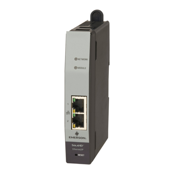
- Page 1 User Guide A272-365 Rev. 1 6/2022 Ethernet/IP Communications Module (SCM-E-EIP) SCM SolaHD Communication Module For use with SolaHD™ SDN-D Power Supplies...
-
Page 2: Table Of Contents
3. MONITORING ..........................22 3.1 WEBSERVER MONITORING ......................22 3.1.1 PROCEDURE ......................... 22 3.1.2 PARTS ........................... 23 3.1.2.1 MONITORING TAB ......................23 3.1.2.2 NETWORK TAB ......................24 3.1.3 CONFIGURABLE ALARMS ...................... 25 3.1.3.1 ENABLING/DISABLING ALARM FLAGS ................27 Page: 2 Emerson.com/SolaHD... - Page 3 6.6.4 UDT_EMERSON_PARAMETER ....................60 6.6.5 UDT_EMERSON_SCM_CONTROL_DATA ................60 6.7 EMERSON_SCM_INTERFACE ......................60 6.7.1 INPUTS ..........................60 6.7.2 OUTPUTS ..........................61 6.7.3 IN/OUTS ..........................61 7. TROUBLESHOOTING AND TECH SUPPORT ..................62 7.1 TROUBLESHOOTING ........................62 TECHNICAL SUPPORT ........................64 WARRANTY .............................64 Emerson.com/SolaHD Page: 3...
-
Page 4: Revision History
REVISION HISTORY User Guide 6/2022 A272-365 REVISION HISTORY Revision Code Revision Date Description Rev. 1 1/2022 Release for Beta Page: 4 Emerson.com/SolaHD... -
Page 5: Preface
A272-365 6/2022 PREFACE Thank you for purchasing SolaHD SCM-E-EIP! This user manual defines how to use the communication functions of SCM-E-EIP. It also contains important safety instructions that must be followed during the installation and operation of the communication module. -
Page 6: Introduction
IP adapter, the SCM-E-EIP should function properly with any other Ethernet/IP device meeting ODVA certifications. The web server embedded in the SCM-E-EIP should be compatible with any MS Windows-based Internet browser, including Google Chrome, Microsoft Edge, and Mozilla Firefox. Page: 6 Emerson.com/SolaHD... -
Page 7: Safety Instructions
Risk of personal injury and explosion hazard when used in a Class I, Division 2/Class I, Zone 2 environment. Refer to the "Safety Instruction Sheet - SCM Communications Modules" provided with the product or located on our website at www.SolaHD.com. Be sure to adhere to all safety procedures provided in the sheet. Emerson.com/SolaHD Page: 7... -
Page 8: Product Overview
-40°C to 85°C Relative Humidity 5-95% RH Altitude 0 to 3,000m Weight/Dimensions 140 x 25.5 x 106.9 mm, with sliding arm H x W x D 123.3 x 25.5 x 106.9 mm, without sliding arm Net Weight 161g Page: 8 Emerson.com/SolaHD... -
Page 9: Communication Specifications
100 ms maximum Connection type Exclusive-Owner Connection Number of clients that can communicate Class 3 at one time: 6 Explicit message Number of clients that can communicate UCMM at one time: 6 Default IP Address DCHP enabled Emerson.com/SolaHD Page: 9... -
Page 10: Construction
This LED indicator is used to indicate the status of the module. For full details on the status LEDs, refer to the Network and Module Status Indicators section. ETHERNET PORT This dual Ethernet port is used to connect the SCM-E-EIP to the network. Page: 10 Emerson.com/SolaHD... -
Page 11: Network And Module Status Indicators
Connection timeout which this device is the target has timed out. The SCM has detected that its IP Steady Red Duplicate IP address is already in use. Flashing Green / Red Self-test SCM is performing a self-test. Emerson.com/SolaHD Page: 11... -
Page 12: Indicators At Power Up
These cables are inserted to one of the I2C ports of the SCM-E-EIP. For the location of the I2C port, refer to Section 1.3. For the Ethernet port connectors, use a standard RJ45 cable (shielded Cat6 or higher). The sections below show the wiring of the SCM-E-EIP to the SDN-D power supply. Page: 12 Emerson.com/SolaHD... -
Page 13: Wiring: Scm-E-Eip And Sdn-D 1:1 Connection
User Guide 1. PRODUCT OVERVIEW A272-365 6/2022 1.5.1.1 WIRING: SCM-E-EIP AND SDN-D 1:1 CONNECTION The set-up below shows typical connections of one SCM-E-EIP to one SDN-D Power Supply. Emerson.com/SolaHD Page: 13... -
Page 14: Wiring: Scm-E-Eip And Sdn-D 1:2 Connection
1. PRODUCT OVERVIEW User Guide 6/2022 A272-365 1.5.1.2 WIRING: SCM-E-EIP AND SDN-D 1:2 CONNECTION The set-up below shows typical connections of one SCM-E-EIP to two SDN-D Power Supplies. Page: 14 Emerson.com/SolaHD... -
Page 15: Wiring: Scm-E-Eip And Sdn-D Device Level Ring (Dlr) Connection
DLR topology. In this example, each SCM-E-EIP is connected to a single SDN-D Power Supply. This setup also makes use of a ring supervisor, a device that verifies the integrity of the ring, reconfigures the ring to recover from a single fault, and collects diagnostic information for the ring. Emerson.com/SolaHD Page: 15... -
Page 16: Rockwell Allen Bradley Logix Processor
Section 4 Rockwell Allen Bradley Setup. 1.5.2.1 WIRING: ROCKWELL ALLEN BRADLEY LOGIX PROCESSOR STAR TOPOLOGY The set-up below shows the wiring of a SCM-E-EIP - SDN-D Power Supply to a Rockwell Allen Bradley Logix Processor in star topology. Page: 16 Emerson.com/SolaHD... -
Page 17: Wiring: Rockwell Allen Bradley Logix Processor Device Level Ring (Dlr) Topology
A272-365 6/2022 1.5.2.2 WIRING: ROCKWELL ALLEN BRADLEY LOGIX PROCESSOR DEVICE LEVEL RING (DLR) TOPOLOGY The set-up below shows the wiring of a SCM-E-EIP - SDN-D Power Supply to a Rockwell Allen Bradley Logix Processor in ring topology. Emerson.com/SolaHD Page: 17... -
Page 18: Spacing
1. PRODUCT OVERVIEW User Guide 6/2022 A272-365 1.5.3 SPACING The setup below shows the spacing of the SCM-E-EIP to the SDN-D Power Supplies. Please note that all devices are mounted on a standard DIN-rail. Page: 18 Emerson.com/SolaHD... -
Page 19: Process Data
Power supply loaded a reactive load which is less than 150% of Power Boost the rated load but greater than 125% of the rated load. Overtemperature Internal temperature of the power supply exceeding safe Protection operating levels. This occurs when the main transformer temperature exceeds 125°C. Emerson.com/SolaHD Page: 19... -
Page 20: Product Information And Default Comm. Configuration
0.0.0.0 None Read/Write Subnet Mask 0.0.0.0 None Read/Write Gateway Address 0.0.0.0 None Read/Write Host Name Read/Write Domain name Read/Write DNS Server #1 0.0.0.0 None Read/Write DNS Server #2 0.0.0.0 None Read/Write Port 1 Read/Write Port 2 Read/Write Page: 20 Emerson.com/SolaHD... -
Page 21: Network Configuration/ Ip Settings
3. After the download is finished, upack the items on the zip file and run the installer. 4. Connect the SCM-E-EIP to the PC where you installed the HMS IP Config tool, preferably direct connection. 5. Follow the HMS IPConfig User Guide. 6. Click Next until you reach the Registration process. Emerson.com/SolaHD Page: 21... -
Page 22: Monitoring
Windows search bar and pressing Enter. (This step can be skipped.) 4. Once the connection is established, open the desired browser and type the IP address (192.168.1.5) on the address bar. 5. The webserver should be loaded with the default tab opened (Overview tab). Page: 22 Emerson.com/SolaHD... -
Page 23: Parts
The Parameters tab shows all the measurement and calculation data of the devices (SDN-D Power supplies, etc) connected to the communications module. The FRU data of the SCM-E-EIP are also shown in this tab. Emerson.com/SolaHD Page: 23... -
Page 24: Network Tab
Ethernet status. The configuration tab is where the user can change current IP configuration such as the IP address, subnet mask, gateway address, and DNS servers. The status of the DHCP can also be changed in this tab. Page: 24 Emerson.com/SolaHD... -
Page 25: Configurable Alarms
4.5 degrees, the alarm bit will be set to 1 when the temperature is equal to or greater than 94.5 degrees. The alarm bit will be set to 0 when the temperature is less than or equal to 85.5 degrees. Emerson.com/SolaHD Page: 25... - Page 26 (reserved for (reserved for Description Threshold Threshold future use)" future use)" Internal Temp Output Current Register Value <= Threshold <= Threshold 0x00000000 <= Threshold > Threshold 0x00000004 > Threshold <= Threshold 0x00000008 > Threshold > Threshold 0x0000000C Page: 26 Emerson.com/SolaHD...
-
Page 27: Enabling/Disabling Alarm Flags
SCM-E-EIP ignores the value set in the threshold value and always return a 0x0000 value in the alarm flag. The Class 1 Alarm Flag Process Data will also produce a 0x0000 value when ENABLE ALARM is disabled. Emerson.com/SolaHD Page: 27... -
Page 28: Rockwell Allen-Bradley Setup
Class 1 IO connection set-up of the SCM Module to the Allen Bradley CompactLogix using the EDS file method: 1 To import the EDS file, select EDS Hardware Installation Tool under Tools. This will prompt the Rockwell Automation EDS Wizard to open. Page: 28 Emerson.com/SolaHD... - Page 29 User Guide 4. ROCKWELL ALLEN-BRADLEY SETUP A272-365 6/2022 2 Click Next until you reach the Registration process. Emerson.com/SolaHD Page: 29...
- Page 30 4. ROCKWELL ALLEN-BRADLEY SETUP User Guide 6/2022 A272-365 Page: 30 Emerson.com/SolaHD...
- Page 31 User Guide 4. ROCKWELL ALLEN-BRADLEY SETUP A272-365 6/2022 3 Tick Register a single file and click the Browse button to select the EDS file on the host PC. Emerson.com/SolaHD Page: 31...
- Page 32 4. ROCKWELL ALLEN-BRADLEY SETUP User Guide 6/2022 A272-365 4 Click Next until the prompt ends. Page: 32 Emerson.com/SolaHD...
- Page 33 I/O Configuration folder first. Create new module by right clicking Ethernet and selecting New Module. Ethernet is located under the I/O Configuration folder in the Controller Organizer window. SCM-E-EIP can now be filtered using the keyword “SOLA” or “SOLAHD”. Select SCM-E-EIP and click the Create button. Emerson.com/SolaHD Page: 33...
-
Page 34: Rockwell Allen-Bradley Logix Processor Monitoring
To set the device path, click on the RSWho button as shown below. This will scan the network using the network interface card on your PC to locate the PLC. Ensure that the PLC is set to PROG or REM before going online to download the program. Page: 34 Emerson.com/SolaHD... - Page 35 User Guide 4. ROCKWELL ALLEN-BRADLEY SETUP A272-365 6/2022 2 To download the program to the PLC, click on the Go Online button on the Select Recent Communications Path window. Emerson.com/SolaHD Page: 35...
- Page 36 4. ROCKWELL ALLEN-BRADLEY SETUP User Guide 6/2022 A272-365 3 Click ‘Download’ on the next prompt. 4 After downloading the program to the PLC, data can now be accessed through the controller tags. Page: 36 Emerson.com/SolaHD...
-
Page 37: I/O Data And Explicit Messaging Connections
The accuracy defined in the table above is valid over the entire operating input, load, Vout range and 0–60°C • (unless specified otherwise) P1, P2 Temperature (power supply internal ambient temperature) accuracy at > 50°C • Iout accuracy at > 20% of max. operating load • Emerson.com/SolaHD Page: 37... -
Page 38: Class 3 Application Data Interface
CHAR Get Access only Code SDN 1| Manufacturer CHAR Get Access only Name SDN 1| Model CHAR Get Access only Revision SDN 1| Primary UINT8 Get Access only Revision SDN 1| Secondary UINT8 Get Access only Revision Page: 38 Emerson.com/SolaHD... - Page 39 Get Access only Power Boost SDN 1| Count: Input Power UINT16 count Get Access only applied SDN 1| Count: Over- UINT16 count Get Access only Temperature Protection SDN 1| Output Voltage, UINT16 0.01V Get Access only Maximum value Emerson.com/SolaHD Page: 39...
- Page 40 Get Access only value SDN 2| Power Supply Internal UINT16 0.1°C Get Access only Temperature SDN 2| LED UINT8 See Table 4.3.4 Get Access only Status SDN 2| Event BITS16 See Table 4.3.5 Get Access only Flags Page: 40 Emerson.com/SolaHD...
- Page 41 SDN 2| Temperature, UINT16 0.1°C Get Access only Maximum value SDN 1| User Alarm Limit: UINT16 0.01A Set / Get Access Output Current High SDN 1| User Alarm Limit: SINT16 0.1°C Set / Get Access Temperature High Emerson.com/SolaHD Page: 41...
- Page 42 Section 4.3.7 Refer to SDN 1| Event 8 STRUCT Get Access only Section 4.3.7 Refer to SDN 1| Event 9 STRUCT Get Access only Section 4.3.7 Refer to SDN 1| Event 10 STRUCT Get Access only Section 4.3.7 Page: 42 Emerson.com/SolaHD...
- Page 43 Section 4.3.7 Refer to SDN 1| Event 29 STRUCT Get Access only Section 4.3.7 Refer to SDN 1| Event 30 STRUCT Get Access only Section 4.3.7 Refer to SDN 1| Event 31 STRUCT Get Access only Section 4.3.7 Emerson.com/SolaHD Page: 43...
- Page 44 Section 4.3.7 Refer to SDN 1| Event 50 STRUCT Get Access only Section 4.3.7 Refer to SDN 1| Event 51 STRUCT Get Access only Section 4.3.7 Refer to SDN 1| Event 52 STRUCT Get Access only Section 4.3.7 Page: 44 Emerson.com/SolaHD...
- Page 45 Section 4.3.7 Refer to SDN 2| Event 6 STRUCT Get Access only Section 4.3.7 Refer to SDN 2| Event 7 STRUCT Get Access only Section 4.3.7 Refer to SDN 2| Event 8 STRUCT Get Access only Section 4.3.7 Emerson.com/SolaHD Page: 45...
- Page 46 Section 4.3.7 Refer to SDN 2| Event 27 STRUCT Get Access only Section 4.3.7 Refer to SDN 2| Event 28 STRUCT Get Access only Section 4.3.7 Refer to SDN 2| Event 29 STRUCT Get Access only Section 4.3.7 Page: 46 Emerson.com/SolaHD...
- Page 47 Section 4.3.7 Refer to SDN 2| Event 48 STRUCT Get Access only Section 4.3.7 Refer to SDN 2| Event 49 STRUCT Get Access only Section 4.3.7 Refer to SDN 2| Event 50 STRUCT Get Access only Section 4.3.7 Emerson.com/SolaHD Page: 47...
-
Page 48: Scm Led Status Detail
SDN 2| Event 63 STRUCT Get Access only Section 4.3.7 Refer to SDN 2| Event 64 STRUCT Get Access only Section 4.3.7 4.3.3 SCM LED STATUS DETAIL Module Network Decimal Value Hex Value GREEN GREEN GREEN GREEN GREEN GREEN Page: 48 Emerson.com/SolaHD... -
Page 49: Power Supply Led Status Detail
Reserved Reserved Reserved Reserved Reserved Value Reserved Reserved Reserved Reserved Reserved Reserved Reserved Reserved Value Reserved Reserved Reserved Reserved Reserved Reserved Reserved Reserved Power Supply Output Value Reserved Reserved Reserved Reserved Temperature Current Reserved Reserved High Hight Emerson.com/SolaHD Page: 49... -
Page 50: Event Data Structure Detail
Event Start Start No Event (pls. refer also to Event Code) 4.3.7.3 EVENT TIMESTAMP DEFINITION Timestamp Definition Conversion (Little Endian format) Byte [2] Byte [3] Byte [4] Byte [5] Dec (seconds) 0xC8 0x89 0x00 0x00 0x000089C8 35,272 Page: 50 Emerson.com/SolaHD... -
Page 51: Rockwell Software Package
Upon initialization of communication link, the PLC will read the following class 3 data from the SCM and write to the HMI UDT: SCM Part Number • SCM Serial Number • SCM Manufacturer Lot Code • SCM Manufacturer Name • Emerson.com/SolaHD Page: 51... -
Page 52: Message Group 2: Msg_Periodic_Read
PS 1 & 2 Event 0 Timestamp • PS 1 & 2 Event 1 Code • PS 1 & 2 Event 1 Type • PS 1 & 2 Event 1 Timestamp • PS 1 & 2 Event 2 Code • Page: 52 Emerson.com/SolaHD... -
Page 53: Message Group 4: Msg_User_Parameter_Write
PS 1 & 2 User Alarm Limit: Alarm Flag Enable • The PLC program will monitor the alarm flags from the SCM as class 1 data. If the alarms are triggered, the PLC will set corresponding alarms in the PLC. Emerson.com/SolaHD Page: 53... -
Page 54: Advanced Monitoring Scenarios
The PLC program will allow the user to enter early warning and critical warning total-on-time thresholds. The PLC will monitor the total use-times of the power supplies and set a warning condition when the use-time reaches the early warning threshold as well as an alarm when it reaches the critical warning threshold. Page: 54 Emerson.com/SolaHD... -
Page 55: Controller Tags
AOI_SCM_Interface. MSGs – A message instance tag will need to be created for each parameter that is read • through class 1 messaging. Emerson.com/SolaHD Page: 55... -
Page 56: Udts
1 = Off (No Power, No IP Address) 2 = Steady Green (Connected) 3 = Blinking Green (No Connections) 4 = Blinking Red (Connection Timeout) 5 = Steady Red (Duplicate IP) 6 = Blinking Green/Red (Self-Test) rSCM_Ambient_Temp Real Ambient temperature in degrees Celsius Page: 56 Emerson.com/SolaHD... - Page 57 PS2’s output current rTotal_Output_Current Real Total output current of SDN1 and SDN2 User input for the time-on early rTime_On_Warning_Limit Real warning alarm limit (in hours) rTime_On_Critical_Alarm User input for the time-on critical alarm Real _Limit limit (in hours) Emerson.com/SolaHD Page: 57...
-
Page 58: Udt_Emerson_Ps
Real 129/229 degrees Celsius rOutput_Voltage Real 108/208 Present output voltage in Volts rOutput_Current Real 109/209 Present output current in Amps rInput_Voltage Real 110/210 Present input voltage in Volts Present internal temperature in rInternal_Temperature Real 111/211 degrees Celsius Page: 58 Emerson.com/SolaHD... -
Page 59: Udt_Emerson_Scm_Alarm
10% or more in the last 24 hours bPS2_Total_Current_ Bool Either the warning limit for combined current or single Warning supply current has been reached; depends on whether the SCM is configured for redundant or increased power mode Emerson.com/SolaHD Page: 59... -
Page 60: Udt_Emerson_Parameter
There will be a single Emerson_SCM_Interface that contains the bulk of the logic that is not read/write data parsing. 6.7.1 INPUTS iSCM_Configuration_Mode – An integer that user can set to specify the SCM • configuration (0 = none; 1 = redundant supply mode; 2 = increased power mode) Page: 60 Emerson.com/SolaHD... -
Page 61: Outputs
This will be used to trigger writing user parameters via the MSG_User_Parameter_Write. 6.7.3 IN/OUTS SCM_Control_Data – A series of arrays that acts as an intermediary between the • message instructions and AOI SCM_HMI – Read and write the UDT_Emerson_SCM_HMI • Emerson.com/SolaHD Page: 61... -
Page 62: Troubleshooting And Tech Support
One of the PSUs connected to the Check the status of the SDN-D Module LED indicator is SCM-E-EIP encountered a major power supplies connected to the blinking red. recoverable fault. SCM and correct any issues. Page: 62 Emerson.com/SolaHD... - Page 63 The GUI logo and format is The SCM-E-EIP internal filesystem Contact technical support. not Emerson. has been damaged or corrupted Restart the affected SDN-D Power supply. The SDN-D Power Supply data SDN-D Power Supply and/or...
-
Page 64: Technical Support
Note that unit specifications are subject to change without notice. TECHNICAL SUPPORT Website: www.solahd.com Technical Support E-Mail: solahd.technicalservices@emerson.com Toll-Free: (800) 377-4384 USA: (847) 268-6651 WARRANTY Please see the “Terms & Conditions of Sale” document within the UPS packaging. While every precaution has been taken to ensure accuracy and completeness in this manual, Appleton Grp LLC d/b/a Appleton Group assumes no responsibility, and disclaims all liability for damages resulting from use of this information or for any errors or omissions. - Page 66 The Emerson logo is a trademark and service mark of Emerson Electric Co. Appleton Grp LLC d/b/a Appleton Group. SolaHD is a registered trademark of Appleton Grp LLC. All other marks are the property of their respective owners. © 2022 Emerson Electric Co. All rights reserved. United States...