Garmin GNS 400W Series Maintenance Manual
Hide thumbs
Also See for GNS 400W Series:
- Pilot's manual & reference (220 pages) ,
- Pilot's manual addendum (19 pages)

Related Manuals for Garmin GNS 400W Series


Summary of Contents for Garmin GNS 400W Series
- Page 1 GNS 400W SERIES MAINTENANCE MANUAL GPS 400W, GNC 420W/AW, and GNS 430W/AW 190-00356-05 October 2008 Revision A...
- Page 2 Garmin Corporation. Garmin Corporation grants permission to download a single copy of this manual and of any revision to this manual onto a hard drive or other electronic storage medium to...
- Page 3 NOTE This product contains a lithium battery that must be recycled or disposed of properly. Battery replacement and removal must be performed by professional services. GNS 400W Series Maintenance Manual Page i 190-00356-05 Rev. A...
- Page 4 A-1 to A-8 SERVICE BULLETIN HISTORY The following table identifies hardware service bulletins for the GNS 400W series of units. The table below is subject to change without notice. Authorized Garmin Sales and Service Centers are encouraged to access the most up-to-date bulletin and advisory information on the Garmin Dealer Resource web site at www.garmin.com using their Garmin-provided user name and...
- Page 5 011-01061-10 GRAY 011-01061-40 BLACK NOTE 1 011-01061-50 GRAY NOTE 1 Designations: A— 28 VDC Unit with 16 watt comm transmitter. Note 1—The unit is an upgrade of the non-WAAS unit. GNS 400W Series Maintenance Manual Page iii 190-00356-05 Rev. A...
-
Page 6: Table Of Contents
Troubleshooting Method II – Minimum Performance Tests ........4-7 Comm Board Tests ....................4-20 VOR/LOC Receiver Testing................... 4-44 Glideslope Receiver Tests..................4-53 Testing Failures....................... 4-56 Return To Service Tests..................4-57 Page iv GNS 400W Series Maintenance Manual Rev. A 190-00356-05... - Page 7 GPS 400W ........................ 6-1 GNC 420W ....................... 6-2 GNC 420AW ......................6-2 GNS 430W........................ 6-3 GNS 430AW......................6-3 APPENDIX A—SYSTEM INTERCONNECTS P4001 Main Connector .................... A-1 P4002 Comm Connector..................A-5 P4006 Connector...................... A-6 GNS 400W Series Maintenance Manual Page v 190-00356-05 Rev. A...
- Page 8 Fault Messages and Recommended Actions............. 4-2 Configuration and Test Page Names................. 4-8 Unit Input Power Requirements................4-9 Unit Board Configurations..................4-13 Com Power Requirements ..................4-23 Testing Failures-Main Board .................. 4-56 Page vi GNS 400W Series Maintenance Manual Rev. A 190-00356-05...
-
Page 9: Section 1-Introduction
INTRODUCTION This manual contains maintenance information for the GNS 400 “W” (WAAS) series of units. All units in the GNS 400W series affected by this manual are listed in the table on page iii. MAINTENANCE/SUPPORT PHILOSOPHY Avionics shop repair is limited to replacing the parts listed in Section 6. All repairs can be made at the bench with an appropriate replacement spare part. -
Page 10: Warranty Information
___________________________________________________________ WARRANTY INFORMATION This Garmin product is warranted to be free from defects in materials or workmanship for two years from the date of purchase. For WAAS upgrade of this product, the warranty is separate and described in the service record or statement. -
Page 11: Section 2-Unit Description
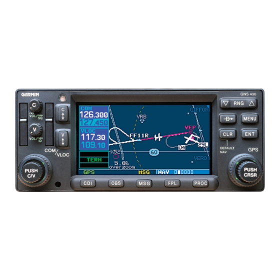
___________________________________________________________ SECTION 2 UNIT DESCRIPTION This section gives a brief decsription of each unit in the GNS 400W series. INTRODUCTION All units in the 400W series are 6.25 inches wide and 2.66 inches high. The display on all units is a 240 by 128 pixel color LCD. -
Page 12: Front Panel Layout
Interfacing with other flight instruments such as a moving map, autopilot, CDI/HIS (including OBS), indicators, altitude encoder/serializer, fuel management system, and annunciators. • Operation from 11 to 33 volts. • Terrain situational awareness (TERRAIN) functions and associated databases. Page 2-2 GNS 400W Series Maintenance Manual Rev. A 190-00356-05... -
Page 13: 2.3.2 Gnc 420W
VOR / ILS localizer receiver. • VOR audio Morse code identifier output. • Remote DME channeling. • Interface with other flight instruments such as autopilot, CDI/HSI (including OBS) and OBI. GNS 400W Series Maintenance Manual Page 2-3 190-00356-05 Rev. A... -
Page 14: Technical Specifications
Active Area 3.29” (W) x 1.75” (H) Resolution 240 x 128 pixels Viewing Angle (with a 2:1 contrast ratio, min) Left/Right: Up: Down: 40° 40° 40° Viewing Distance 36 inches maximum Page 2-4 GNS 400W Series Maintenance Manual Rev. A 190-00356-05... -
Page 15: Gps Specifications
± 275 nanoseconds of UTC second Datum WGS-84 SATCOM Compatibility SATCOM compatibility is dependent upon antenna selection. Antenna Power Supply 35 mA typical, 40 mA max at 4.7 V dc GNS 400W Series Maintenance Manual Page 2-5 190-00356-05 Rev. A... - Page 16 * C37d Class 4 & 6 may not provide suitable COM transmit range for some high-altitude aircraft. **Specifications shown apply at nominal input voltages of 13.75 V dc or 27.5 V dc, as applicable, and with a nominal 50 ohm resistive load at the antenna connector. Page 2-6 GNS 400W Series Maintenance Manual Rev. A 190-00356-05...
-
Page 17: Vor Specifications
2500 Hz. Except the 1020 Hz Ident Tone is at least 20 dB down in voice mode. Audio Distortion The distortion in the receiver audio output does not exceed 10% at all levels up to 100 mW. GNS 400W Series Maintenance Manual Page 2-7 190-00356-05 Rev. A... -
Page 18: Loc Specifications
2500 Hz. Except the 1020 Hz Ident Tone is at least 20 dB down in voice mode. Audio Distortion The distortion in the receiver audio output does not exceed 10% at all levels up to 100 mW. Page 2-8 GNS 400W Series Maintenance Manual Rev. A 190-00356-05... -
Page 19: Glideslope Specifications
In the absence of 150 Hz modulation. c) In the absence of 90 Hz modulation. d) In the absence of both 90 Hz and 150 Hz modulation. e) In the absence of RF. GNS 400W Series Maintenance Manual Page 2-9 190-00356-05 Rev. A... - Page 20 ___________________________________________________________ Blank Page Page 2-10 GNS 400W Series Maintenance Manual Rev. A 190-00356-05...
-
Page 21: Section 3-Theory Of Operation
(a failure in one of the supplies will not cause a failure of the other supply). The power supplies are duplicated so that, in a case where the main power supplies fail, the Com Radio is capable of continued operation. GNS 400W Series Maintenance Manual Page 3-1 190-00356-05... - Page 22 The interface signals also include EMI/RFI suppression. In many cases, this uses EMI beads along with capacitors. When the EMI beads are used on the same signals as the lightning Page 3-2 GNS 400W Series Maintenance Manual Rev. A 190-00356-05...
-
Page 23: Vhf Communications Transceiver (Com Board)
Class C and E device as described in RTCA DO-186a, indicating that it has channel spacing modes of 8.33 kHz and 25 kHz, with offset carrier capability in 25 kHz mode. GNS 400W Series Maintenance Manual Page 3-3 190-00356-05 Rev. -
Page 24: Nav Board
The WAAS GPS Receiver is a twelve channel parallel receiver that is capable of tracking and using up to twelve visible satellites for position, velocity, and time calculations. INVERTER BOARD The Inverter Board supplies high voltage for display operation. Page 3-4 GNS 400W Series Maintenance Manual Rev. A 190-00356-05... -
Page 25: Interface Board
EIA standard RS-232C. The Video Board connects to the Main Board by the flex cable. KEYBOARD The Keyboard consists of snap-dome keys, photocell, and LEDs for backlighting display operation. GNS 400W Series Maintenance Manual Page 3-5 190-00356-05 Rev. A... - Page 26 ___________________________________________________________ Blank Page Page 3-6 GNS 400W Series Maintenance Manual Rev. A 190-00356-05...
-
Page 27: Section 4-Troubleshooting/Testing
LIMITATIONS/SCOPE If any testing which is required and/or desired falls outside of the scope of what is described, return the unit to Garmin for repair. NOTE All units contains static sensitive components. Observe proper anti-static procedures during testing. -
Page 28: Fault Messages And Recommended Actions
Return the unit for service. determined that the boot block has become corrupted. Check the applicable flex CDI key stuck cable. Replace the keyboard. Replace the CDU. Return the unit for service. Page 4-2 GNS 400W Series Maintenance Manual Rev. A 190-00356-05... - Page 29 Check for adequate excessive display ventilation or check cooling backlighting temperature. The airflow. backlighting has been Return the unit to Garmin for automatically dimmed to repair. reduce the temperature. COMM has failed The unit has detected a Replace the comm board.
- Page 30 TAWS/TERRAIN units). data does not appear on the Replace the terrain data card. map page. Other unit Replace the map board. functions continue to work Return the unit for service. normally. Page 4-4 GNS 400W Series Maintenance Manual Rev. A 190-00356-05...
- Page 31 Replace the terrain data card. database. Terrain functionality is not available If the terrain database is not the cause, return the unit to Garmin for service. GNS 400W Series Maintenance Manual Page 4-5 190-00356-05 Rev. A...
- Page 32 VLOC not responding Internal system-to-system Check the applicable flex communication between the cable. main processor and the Replace the nav receiver. VLOC receiver has failed. Return the unit for service. Page 4-6 GNS 400W Series Maintenance Manual Rev. A 190-00356-05...
-
Page 33: Troubleshooting Method Ii - Minimum Performance Tests
When the fault message method is unsuccessful, the following minimum performance tests may be performed to help troubleshoot and identify a defective board. Replace the defective part or send the unit to Garmin if the unit fails to pass any test. NOTES A misaligned board may cause incorrect test results. -
Page 34: Configuration And Test
COMM Setup COMM Setup GS Setup VOR Discrete Inputs VOR Discrete Inputs VOR/LOC/GS CDI VOR Discrete Outputs VOR/LOC/GS ARINC 429 Config VOR/LOC/GS CDI GPS Vertical Offset VOR Setup/Status/Loopback Main Information Page 4-8 GNS 400W Series Maintenance Manual Rev. A 190-00356-05... -
Page 35: Unit Input Power Requirements
All units operate with external power from 9-33 V dc. The power consumption must not exceed the limits shown in Table 4-3 with the display backlight at maximum brightness. Return the unit to Garmin for service if any unit fails the power requirement checks. Table 4-3. Unit Input Power Requirements... - Page 36 If a lighting bus option other than photo is selected, and the lighting bus control is turned to its minimum (daytime) setting, the display brightness will default to tracking the unit photocell. Lighting BUS HI: (J1-39) • Lighting BUS LO: (J1-40) • Page 4-10 GNS 400W Series Maintenance Manual Rev. A 190-00356-05...
-
Page 37: Main Analog Input Test Page
Starting from the display pattern test page (Figure 4-3), use the ‘RNG’ buttons to cycle through all of the display patterns to verify all pixels are driven and color contrast is acceptable. Figure 4-3. Display Pattern Test Page (Test Mode) GNS 400W Series Maintenance Manual Page 4-11 190-00356-05... -
Page 38: Waas Gps Status Page
1. Command output high and measure output on oscilloscope. Measure at J1-16. Verify voltage > 4 volts. 2. Command output low and measure output on oscilloscope. Verify voltage < 0.4 volts. Page 4-12 GNS 400W Series Maintenance Manual Rev. A 190-00356-05... -
Page 39: Main Cdi/Obs Configuration Page
-300 ± 15 mV Main Vertical Up+, Down+ Outputs Load: 333 ohms (three 1000 ohm loads) across J1-27 and J1-28. Command the test via the main CDI/OBS configuration page (Figure 4-5). GNS 400W Series Maintenance Manual Page 4-13 190-00356-05 Rev. A... - Page 40 13.8 V operation then this test should not be run at 27.5 V. Command the test via the VOR/LOC/GS CDI configuration page (Figure 4-6). Measure at J1-18. OUT OF VIEW IN VIEW AIRCRAFT POWER - 1.5 V dc min V dc max Page 4-14 GNS 400W Series Maintenance Manual Rev. A 190-00356-05...
-
Page 41: Main Discrete Outputs Page
ILS/GPS APPR (J1-14) Command Output To: ACTIVE INACTIVE SPEC 0.8 V dc max 4.5 V dc min Discrete Switch and Altitude Inputs Figure 4-7. Main Discrete Inputs Page (Test Mode) GNS 400W Series Maintenance Manual Page 4-15 190-00356-05 Rev. A... - Page 42 The ARINC 429 receivers must be able to receive differential voltages between line A and line B of not less than 6.5 volts or greater than 13.0 volts. A differential voltage of less than 2.5 volts Page 4-16 GNS 400W Series Maintenance Manual Rev. A 190-00356-05...
-
Page 43: Main Rs232 Configuration Page
V) is interpreted as a logic 0. The input resistance to ground is 3 - 7 K ohm over a voltage range of 3 to 15 V dc with an input capacitance of < 2500 pF. GNS 400W Series Maintenance Manual Page 4-17 190-00356-05 Rev. - Page 44 The load used in the OBS test consists of a calibrated OBS resolver, precision track selector or equivalent, and must be connected to the GPS OBS inputs. The OBS bearing must be consistent to within ± 2 degrees of the bearing setting. Page 4-18 GNS 400W Series Maintenance Manual Rev. A 190-00356-05...
- Page 45 Set test set to the angles given in the table below. Verify the angle via the main CDI/OBS config test page. 60 ± 2 150 ± 2 240 ± 2 330 ± 2 GNS 400W Series Maintenance Manual Page 4-19 190-00356-05 Rev. A...
-
Page 46: Comm Board Tests
(which corresponds to 7.07 Vrms across that load). Closed Squelch The condition of the squelch in which audio is suppressed. Open Squelch The condition of the squelch in which audio is not suppressed. Page 4-20 GNS 400W Series Maintenance Manual Rev. A 190-00356-05... - Page 47 This audio is the summation of the receiver, microphone intercom and sidetone. COMM AUDIO IN HI ----- NAV AUDIO IN HI ----- AUX AUDIO IN HI ----- AIRCRAFT POWER Aircraft power input. AIRCRAFT POWER Aircraft power input. GNS 400W Series Maintenance Manual Page 4-21 190-00356-05 Rev. A...
- Page 48 Ground COMM AUDIO LO Floating COMM AUDIO IN LO Ground GROUND Ground GROUND Ground NAV AUDIO IN LO Ground AUX AUDIO IN LO Ground 4 OHM AUDIO Ground OUTPUT LO Page 4-22 GNS 400W Series Maintenance Manual Rev. A 190-00356-05...
- Page 49 3.0 A TX Mode watt units only) ± 0.4 V J2 Pin 11 & 12 +27.5 (16 watt 3.0 A TX Mode units only) Table 4-5. Comm Board Power Requirements GNS 400W Series Maintenance Manual Page 4-23 190-00356-05 Rev. A...
- Page 50 200 mV to 10 µV. The audio output must return to within 3 dB of the normal steady-state output at 10 µV within 100 msec after transferring from a transmit to a receive state. Page 4-24 GNS 400W Series Maintenance Manual Rev. A 190-00356-05...
- Page 51 5. Set the RF level to –107 dBm (2 µV). 6. Measure the SNR (average 10 readings). 7. Enable the TX INTERLOCK pin (low or grounded). Set the RF level to –92 dBm (11.25 µV). GNS 400W Series Maintenance Manual Page 4-25 190-00356-05 Rev. A...
- Page 52 Minimum Volume Output: Audio Output < 22 mVrms • Squelched Audio Output: Audio Output < 2 mVrms • Signal Pin Signal Name Reference Pin Reference Name Load J2-7 COMM AUDIO HI J2-19 COMM AUDIO LO 500 Ohms Page 4-26 GNS 400W Series Maintenance Manual Rev. A 190-00356-05...
- Page 53 Microphone intercom audio level ≥ 7.07 Vrms • Microphone intercom distortion < 10% • Signal Pin Signal Name Reference Pin Reference Name Load J2-7 COMM AUDIO HI J2-19 COMM AUDIO LO 500 Ohms GNS 400W Series Maintenance Manual Page 4-27 190-00356-05 Rev. A...
- Page 54 1.5 and 6.0 µV, modulated 85% at 8 kHz. The carrier squelch must close the audio output within 6 dB of opening squelch level. Carrier squelch operation must be tested at the channels shown below in 25 kHz and 8.33 kHz channel modes. Page 4-28 GNS 400W Series Maintenance Manual Rev. A 190-00356-05...
- Page 55 Repeat steps 1-8 at 127.000 mHz and 136.975 mHz. Verify the following: Squelch open point: 6.3 µV ≤ X ≤ 25 µV. • Hysteresis: Vrms (ac) < 10 mVrms. • GNS 400W Series Maintenance Manual Page 4-29 190-00356-05 Rev. A...
- Page 56 Repeat steps 1-8 for 127.000 mHz and 136.975 mHz. Verify the following: Squelch open point: 1 µV ≤ X ≤ 4 µV. • Hysteresis: ac Vrms < 10 mVrms. • Page 4-30 GNS 400W Series Maintenance Manual Rev. A 190-00356-05...
- Page 57 (open time). Signal Pin Signal Name Reference Pin Reference Name Load J2-7 COMM AUDIO HI J2-19 COMM AUDIO LO 500 Ohms GNS 400W Series Maintenance Manual Page 4-31 190-00356-05 Rev. A...
- Page 58 Set the RF frequency to 127 – offset frequency (8 kHz or 2.778 kHz for 25 or 8.33 spacing respectively). Measure the AGC voltage. This is the fc (-) voltage. Verify (reference AGC voltage) – (offset AGC voltage) ≤ 0. Page 4-32 GNS 400W Series Maintenance Manual Rev. A 190-00356-05...
- Page 59 Spurious response tests must be conducted at image frequencies (channel frequency + 42.8 mHz) and at half IF frequencies (channel frequency + 10.7 mHz). Measurements are performed at channel 127.000 with image and half IF frequencies shown in the following table: GNS 400W Series Maintenance Manual Page 4-33 190-00356-05...
- Page 60 Output Level: 10 mV • Modulation: 30% • Audio Frequency: 1 kHz • Measure the IF AGC voltage. Verify (the reference IF AGC voltage) – (the measured IF AGC voltage) > 0. Page 4-34 GNS 400W Series Maintenance Manual Rev. A 190-00356-05...
- Page 61 87.5 and 107.9 mHz. Signal Pin Signal Name Reference Pin Reference Name Load J2-7 COMM AUDIO HI J2-19 COMM AUDIO LO 500 Ohms Manually test per instructions found in DO186a 2.2.11. GNS 400W Series Maintenance Manual Page 4-35 190-00356-05 Rev. A...
- Page 62 2 µV. Measure the SNR (averaged over 10 readings). Store the result. Repeat steps 1-4 for each birdie channel. Verify the measured SNR ≥ 6.0 dB. Page 4-36 GNS 400W Series Maintenance Manual Rev. A 190-00356-05...
- Page 63 400 Hz adjusted to a level that reduces the S+N/N of the desired signal from 20 dB to 14 dB. Signal Pin Signal Name Reference Pin Reference Name Load J2-7 COMM AUDIO HI J2-19 COMM AUDIO LO 500 Ohms Test manually per instructions found in DO186a 2.2.16. GNS 400W Series Maintenance Manual Page 4-37 190-00356-05 Rev. A...
- Page 64 The microphone compressor attack time must be less than 20 msec and the decay time • must be greater than 400 msec. 1. Apply a standard microphone test signal. 2. Set the carrier frequency to 118.000 mHz. 3. Key the transmitter. Page 4-38 GNS 400W Series Maintenance Manual Rev. A 190-00356-05...
- Page 65 The RF carrier frequency must be within 0.0005% (5 PPM) of the selected channel frequency when the transmitter is modulated with a standard microphone input signal. Measure at channels 118.500, 127.500, and 136.500. 1. Set the unit to 136.500 mHz. GNS 400W Series Maintenance Manual Page 4-39 190-00356-05 Rev. A...
- Page 66 350 to 2500 Hz, when the audio input is held constant at the value which produces 70% modulation at the frequency of maximum response. Measure at channel 127.500. Page 4-40 GNS 400W Series Maintenance Manual Rev. A 190-00356-05...
- Page 67 • 1. Set the unit to 118.500 mHz. 2. Key the microphone. 3. Measure the peak using measurement averaging. 4. Unkey the microphone. 5. Verify result is ≤ 36 dBm. GNS 400W Series Maintenance Manual Page 4-41 190-00356-05 Rev. A...
- Page 68 350 Hz to 2500 Hz in 100 Hz increments. 1. Set the unit to 127.500 mHz. 2. Generate and apply a standard microphone audio test signal. 3. Key the microphone. 4. Measure the AM modulation depth. Page 4-42 GNS 400W Series Maintenance Manual Rev. A 190-00356-05...
- Page 69 11. Measure the AM depth in dB while sweeping the audio signal from 400-2500 Hz in 100 Hz steps. 12. Record the max and min levels. 13. Unkey the microphone. 14. Verify that the difference between the max and min values is ≤ 6 dB. GNS 400W Series Maintenance Manual Page 4-43 190-00356-05 Rev. A...
-
Page 70: Vor/Loc Receiver Testing
RS232 Transmitter Load (VLOC SERIAL OUT) The standard RS232 transmitter load is 3000 ohms measured from the RS232 serial output to ground. One standard load is connected between VLOC SERIAL OUT J10-10 and GND J10-4. Page 4-44 GNS 400W Series Maintenance Manual Rev. A 190-00356-05... - Page 71 A standard VOR centering signal is a standard VOR test signal in which the difference in phase between the reference and variable phase signal is equal (±0.3 degrees) from the setting of the equipment course selector. GNS 400W Series Maintenance Manual Page 4-45 190-00356-05...
- Page 72 A standard localizer audio test signal is a standard localizer test signal to which is added a 1020 Hz signal amplitude modulating the carrier 30%. Standard Audio Test Signal A standard audio test signal is an RF carrier amplitude modulated 30% at 1020 Hz. Page 4-46 GNS 400W Series Maintenance Manual Rev. A 190-00356-05...
- Page 73 -27 dBm using a standard VOR audio test signal at modulation frequencies of 350 Hz, 1000 Hz, and 2500 Hz. VOR AGC Measure NAV AUDIO HI J6-16 with respect to NAV AUDIO LO (GND) J6-17. Must be in IDENT mode to pass 1000 Hz tone. GNS 400W Series Maintenance Manual Page 4-47 190-00356-05 Rev. A...
- Page 74 NAV AUDIO HI J6-16 and NAV AUDIO LO J6-17 outputs with a Standard VOR Audio Test signal with modulation frequency of 1020 Hz at 108.00 mHz or with a Standard Localizer Audio Test signal with modulation frequency of 1020 Hz at 108.10 mHz. Page 4-48 GNS 400W Series Maintenance Manual Rev. A 190-00356-05...
- Page 75 –106.5 dBm RF level Standard VOR Deviation Signal at 108.00 mHz with OBS and signal generator bearings set to 150 degrees ‘FROM’. The receiver sensitivity must meet the following requirements with a -103.5 dBm RF level applied to the RF input: GNS 400W Series Maintenance Manual Page 4-49 190-00356-05 Rev. A...
- Page 76 When the level of a standard localizer deviation test signal produces 50% (0.0465 ddm) • or less of standard deflection of the deviation indicator. Note: there is 2 dB of hysterisis on the LOC flag output. Page 4-50 GNS 400W Series Maintenance Manual Rev. A 190-00356-05...
- Page 77 IF AGC J6-7 output with a -93 dBm Standard Localizer Audio Test Signal must not be less than - 13 dBm. Centering Accuracy The centering error measured through VLOC SERIAL OUT J10-10 must be less than 0.00465 ddm (4.5 millivolts (5%)) using a Standard Localizer Centering Test Signal. GNS 400W Series Maintenance Manual Page 4-51 190-00356-05 Rev. A...
- Page 78 With a -53 dBm signal amplitude modulated 30% at 1 kHz, the total harmonic distortion measured at the NAV AUDIO HI J6-16 and NAV AUDIO LO J6-17 outputs must be less than Page 4-52 GNS 400W Series Maintenance Manual Rev. A 190-00356-05...
-
Page 79: Glideslope Receiver Tests
A standard glideslope deviation test signal is a standard glideslope test signal in which the difference in depth of modulation of the 90 and 150 Hz signals is 0.091 ± 0.002 ddm. GNS 400W Series Maintenance Manual Page 4-53 190-00356-05... - Page 80 The receiver sensitivity variation must not be greater than 3dB when the input frequency is varied from 329.15 to 335 mHz. Centering Accuracy The centering accuracy measured through G/S SERIAL_OUT must be 0 ± .0091 ddm when using the standard glideslope centering test signal. Page 4-54 GNS 400W Series Maintenance Manual Rev. A 190-00356-05...
- Page 81 SERIAL_OUT: When the RF level of a standard deviation test signal produces 50% or less of standard deflection of the deviation indicator: In the absence of 150 Hz modulation. • GNS 400W Series Maintenance Manual Page 4-55 190-00356-05 Rev. A...
-
Page 82: Testing Failures
Return the unit for service Memory Battery Voltage Replace Memory Battery Display Pattern Test Check Applicable Flex Replace CDU Return the unit for service Display Max Level Test Replace Inverter Board Page 4-56 GNS 400W Series Maintenance Manual Rev. A 190-00356-05... -
Page 83: Return To Service Tests
The minimum performance tests contained in this section of the manual may also be used as a return to service test. GNS 400W Series Maintenance Manual Page 4-57 190-00356-05... - Page 84 ___________________________________________________________ Blank Page Page 4-58 GNS 400W Series Maintenance Manual Rev. A 190-00356-05...
-
Page 85: Tools
Inspect wires and cables for breaks in insulation or tears. UNIT DESCRIPTION All units are nearly identical in their electrical and mechanical design and board location. Table 5-1 identifies the board configuration for each unit in the 400W series. GNS 400W Series Maintenance Manual Page 5-1 190-00356-05 Rev. A... - Page 86 3. Grasp the top and bottom surfaces of the swing arm handle between your thumb and forefinger, and pull directly away from the face of the unit to remove the data card. Page 5-2 GNS 400W Series Maintenance Manual Rev. A 190-00356-05...
-
Page 87: Data Card Slot Locations
___________________________________________________________ Figure 5-1. Data Card Slot Locations Figure 5-2. Data Card Insertion/Removal Detail GNS 400W Series Maintenance Manual Page 5-3 190-00356-05 Rev. A... - Page 88 1. Connect all cables and flex connections connecting the CDU Assembly (4) to the rest of the unit. 2. Install two screws (5) attaching CDU Assembly to Main Chassis (3). 3. Install Top Cover (section 5.4.2.2). Page 5-4 GNS 400W Series Maintenance Manual Rev. A 190-00356-05...
-
Page 89: Top Assembly
___________________________________________________________ Figure 5-3. Top Assembly GNS 400W Series Maintenance Manual Page 5-5 190-00356-05 Rev. A... - Page 90 Chassis. 2. Connect Ribbon Cable Strip (3). 3. Install Shoulder Screws (6) securing the rear hinge (7). Fold the two chassis together. 4. Install Screw (4). 5. Install Screw (5). Page 5-6 GNS 400W Series Maintenance Manual Rev. A 190-00356-05...
-
Page 91: Main And Nav Chassis
___________________________________________________________ Figure 5-4. Main and Nav Chassis GNS 400W Series Maintenance Manual Page 5-7 190-00356-05 Rev. A... -
Page 92: Fan Replacement
1. Install Fan (4) with Shield (3) from top using three screws (2). 2. Connect the Red and Black Fan wires (1) to Main Board. 3. Fasten Main and Nav Chassis. Figure 5-5. Fan Replacement Page 5-8 GNS 400W Series Maintenance Manual Rev. A 190-00356-05... - Page 93 3. Install two screws (6) and attach 25 pin connector to Main Chassis (7). 4. Solder Buss Wire (Detail A) from Comm Board (5) to Coax Connector (11). 5. Install three Comm Board Covers (4). GNS 400W Series Maintenance Manual Page 5-9 190-00356-05...
-
Page 94: Main Chassis Bottom Cavity
___________________________________________________________ Figure 5-6. Main Chassis Bottom Cavity Page 5-10 GNS 400W Series Maintenance Manual Rev. A 190-00356-05... - Page 95 3. Attach the 78-pin connector to Main Chassis (5) using two screws (6). 4. Attach WAAS GPS Module to Main Board. 5. Connect GPS Ribbon Cable to the Main Board (3). 6. Install CDU Assembly. GNS 400W Series Maintenance Manual Page 5-11 190-00356-05 Rev. A...
-
Page 96: Main Chassis Top Cavity
___________________________________________________________ Figure 5-7. Main Chassis Top Cavity Page 5-12 GNS 400W Series Maintenance Manual Rev. A 190-00356-05... - Page 97 4. Verify the Memory Battery Low message does not appear. 5. Turn unit off and carefully turn it over. 6. Verify memory battery voltage (measure from positive side of the battery to ground) is at least +2.9 V dc. GNS 400W Series Maintenance Manual Page 5-13 190-00356-05 Rev. A...
- Page 98 ___________________________________________________________ Figure 5-8. Memory Battery Location on the Main Board Page 5-14 GNS 400W Series Maintenance Manual Rev. A 190-00356-05...
- Page 99 3. Disconnect Ribbon Cable (3) from Glideslope Board (10). 4. Unsolder Connector Wire from Coax Connector (Detail A). 5. Remove three screws (11) that attach Glideslope Board (10) to Nav Chassis (7) and remove Glideslope Board. GNS 400W Series Maintenance Manual Page 5-15 190-00356-05 Rev. A...
- Page 100 2. Solder connector wire from Coax Connector (Detail A). 3. Connect Ribbon Cable (3) from Glideslope Board (10). 4. Install Glideslope Board RF Cover (9). 5. Join Main Chassis to Nav Chassis. Page 5-16 GNS 400W Series Maintenance Manual Rev. A 190-00356-05...
-
Page 101: Nav Chassis Cavity
___________________________________________________________ Figure 5-9. Nav Chassis Cavity GNS 400W Series Maintenance Manual Page 5-17 190-00356-05 Rev. A... -
Page 102: Periodic Maintenance
The backlight lamp may dim and the display may not perform as well in direct sunlight conditions over time. The user must determine by observation when the display brightness is not suitable for use. Contact Garmin when the backlight lamp requires service. Battery Replacement Refer to the battery replacement instructions previously described in this section of the manual. -
Page 103: Gps 400W
SECTION 6 SERVICE PARTS LIST This section lists all of the parts that can be ordered from Garmin to repair a unit. The service part numbers listed are referenced back to the figures in Section 5. For orderable part information including availability refer to the Garmin Aviation Distributor Service Parts Price List or contact Garmin directly (contact information listed in Section 1). -
Page 104: 6.2 Gnc 420W
Figure 5-4 (5) Contact Garmin Com Board Figure 5-6 360-00009-00 3V Lithium Battery Figure 5-5 (2) S11-01097-00 GPS WAAS Module Figure 5-3 (4) 371-00001-01 Figure 5-2 (1) 125-00034-01 Main Chassis W/O Studs Page 6-2 GNS 400W Series Maintenance Manual Rev. A 190-00356-05... -
Page 105: 6.4 Gns 430W
Com Board Figure 5-6 360-00009-00 3V Lithium Battery Figure 5-7 (8) S12-00195-22 Nav Board Figure 5-7 (10) S12-00212-11 Glideslope Board Figure 5-5 (2) S11-01097-00 GPS WAAS Module Figure 5-3 (4) 371-00001-01 GNS 400W Series Maintenance Manual Page 6-3 190-00356-05 Rev. A... - Page 106 ___________________________________________________________ Blank Page Page 6-4 GNS 400W Series Maintenance Manual Rev. A 190-00356-05...
-
Page 107: Appendix Asystem Interconnects
This Appendix contains pin descriptions for the rear panel connectors. These descriptions can aid in the fabrication of test cables, test setup, and basic troubleshooting. Figure A-1. Rear Panel Connectors GNS 400W Series Maintenance Manual Page A-1 190-00356-05 Rev. A... -
Page 108: P4001 Main Connector
AIRCRAFT POWER 1 AIRCRAFT POWER 1 MAIN +LEFT MAIN +RIGHT MAIN LATERAL +FLAG MAIN LATERAL –FLAG (GROUND) MAIN +TO MAIN +FROM MAIN +UP MAIN +DOWN MAIN VERTICAL +FLAG MAIN VERTICAL -FLAG (GROUND) Page A-2 GNS 400W Series Maintenance Manual Rev. A 190-00356-05... - Page 109 ALTITUDE COMMON (GROUND) ALTITUDE C4 ALTITUDE C2 ALTITUDE C1 ALTITUDE B4 ALTITUDE B2 ALTITUDE B1 ALTITUDE A4 ALTITUDE A2 ALTITUDE A1 ALTITUDE D4 OBS MODE SELECT AIRCRAFT POWER 2 CDI SOURCE SELECT GNS 400W Series Maintenance Manual Page A-3 190-00356-05 Rev. A...
- Page 110 ___________________________________________________________ COM REMOTE RECALL [1] DEMO MODE SELECT RESERVED AIRCRAFT GROUND AIRCRAFT GROUND [1] Main software version 3.00 or later Page A-4 GNS 400W Series Maintenance Manual Rev. A 190-00356-05...
-
Page 111: P4002 Comm Connector
AIRCRAFT POWER AIRCRAFT POWER RESERVED TRANSMIT INTERLOCK COM REMOTE TRANSFER SPARE INTERCOM MIC LO COM MIC AUDIO LO 500Ω COM AUDIO LO RESERVED AIRCRAFT GROUND AIRCRAFT GROUND RESERVED RESERVED RESERVED GNS 400W Series Maintenance Manual Page A-5 190-00356-05 Rev. A... - Page 112 VOR OBI CLOCK VOR OBI SYNC VOR OBI DATA VLOC REMOTE TRANSFER ILS ENERGIZE GLIDESLOPE +FLAG GLIDESLOPE +DOWN/-FLAG (GLIDESLOPE COMMON) GLIDESLOPE +UP PARALLEL DME – 1MHZ RESERVED VOR/ILS ARINC 429 IN B Page A-6 GNS 400W Series Maintenance Manual Rev. A 190-00356-05...
- Page 113 VOR/ILS ARINC 429 IN A PARALLEL DME – 800KHZ GLIDESLOPE SUPERFLAG PARALLEL DME - 400KHZ PARALLEL DME - 200KHZ AIRCRAFT GROUND PARALLEL DME - 100KHZ PARALLEL DME - 50KHZ AIRCRAFT POWER GNS 400W Series Maintenance Manual Page A-7 190-00356-05 Rev. A...
- Page 114 ___________________________________________________________ Blank Page Page A-8 GNS 400W Series Maintenance Manual Rev. A 190-00356-05...