
Related Manuals for Yale SHAW-BOX YK Series


Summary of Contents for Yale SHAW-BOX YK Series
- Page 1 TRSG ASSEMBLY INSTRUCTION MANUAL P/N: C11746308 , SK , Y80 & ™ ™ 800 Series CRANE KIT ASSEMBLY INSTRUCTION MANUAL P/N: C11746308 REV. AB June 2022 www.columbusmckinnon.com...
-
Page 2: Table Of Contents
TABLE OF CONTENTS 1) SAFETY PRECAUTIONS ........................4 IMPORTANT INFORMATION AND WARNINGS ..................5 2) FABRICATION OF GIRDER(S) FOR BRIDGE BEAM WITH CAPPING CHANNEL ......8 STEP 1: CUT GIRDER AND C-CHANNEL (AS REQUIRED) ..............9 STEP 2: CHECK CAMBER (AS REQUIRED) ....................9 STEP 3: GIRDER AND C-CHANNEL WELDING AT END (AS REQUIRED) .......... - Page 3 TABLE OF CONTENTS 6) FESTOON SYSTEM INSTALLATION .....................34 6.A) PLAN VIEW ............................35 STEP 1: CLAMPING CROSS ARM & CONTROL BOX SUPPORT RAILS ..........36 STEP 2: SPACING FOR CROSS ARMS/SUPPORT RAILS ..............36 STEP 3: C-RAIL MOUNTING ........................37 STEP 4: C-RAIL JOINT ASSEMBLY ......................
-
Page 4: Safety Precautions
CHAPTER 1 SAFETY PRECAUTIONS Safety Alert Symbols Throughout this manual are steps and procedures that can prevent hazardous situations; the following symbols are used to identify the degree or level of hazard seriousness. DANGER, WARNING, CAUTION AND NOTICE Symbol Description Danger Indicates an imminently hazardous situation which, if not avoided, will result in death or... -
Page 5: Important Information And Warnings
IMPORTANT INFORMATION AND WARNINGS Failure to read and comply with any of the limitations noted herein can result in serious bodily injury or death, and/or property damage. Equipment described in this manual is not designed for and should not be used for lifting, supporting, or transporting humans. - Page 6 Read and observe the instructions and warnings contained in this manual. Read and observe any instructions and warning tags attached to the hoist. Check for any damage to the components during shipment. If any damage has occurred, place a claim with the carrier. DO NOT install damaged components. ...
- Page 7 If hoist has a trolley, check that the crane bridge beam is level, straight, and clean. Check that trolley stops are installed, or install trolley stops, at the open end or ends of the beam to prevent the trolley from traveling off the beam. Trolley stops that engage trolley wheels are not recommended.
-
Page 8: Fabrication Of Girder(S) For Bridge Beam With Capping Channel
CHAPTER 2 FABRICATION OF GIRDER(S) FOR BRIDGE BEAM WITH CAPPING CHANNEL (AS REQUIRED) P/N: C11746308 REV. AB June 2022... -
Page 9: Step 1: Cut Girder And C-Channel (As Required)
STEP 1: CUT GIRDER AND C-CHANNEL (AS REQUIRED) WARNING Selection of structural steel beams must be verifi ed by qualifi ed engineer. IT IS IMPORTANT THAT ALL INSTRUCTIONS BE FOLLOWED AND THAT COMPONENT APPLICATION LIMITS NOT BE EXCEEDED. Check your confi guration to see if a capping channel is required. CUT LENGTH TO BE DETERMINED BY SPAN LENGTH STEP 2: CHECK CAMBER (AS REQUIRED) -
Page 10: Step 3: Girder And C-Channel Welding At End (As Required)
STEP 3: GIRDER AND C-CHANNEL WELDING AT END (AS REQUIRED) NOTICE Assembly of beam and channel requires welding. IT IS EXTREMELY IMPORTANT TO THE SAFETY OF THIS BRIDGE THAT THIS WELDING BE DONE BY A COMPETENT WELL-TRAINED WELDER. It is our strong recommendation that the welder used in this construction be qualifi ed as prescribed by the American Welding Society (AWS) -
Page 11: Step 5: Girder And C-Channel Welding (As Required)
STEP 5: GIRDER AND C-CHANNEL WELDING (AS REQUIRED) NOTICE Assembly of beam and channel requires welding. IT IS EXTREMELY IMPORTANT TO THE SAFETY OF THIS BRIDGE THAT THIS WELDING BE DONE BY A COMPETENT WELL-TRAINED WELDER. It is our strong recommendation that the welder used in this construction be qualifi ed as prescribed by the American Welding Society (AWS) -
Page 12: Assembling Bridge Girder To End Trucks (Single Girder)
CHAPTER 3 ASSEMBLING BRIDGE GIRDER TO END TRUCKS (SINGLE GIRDER) P/N: C11746308 REV. AB June 2022... -
Page 13: A) Trsg End Truck Types
3.A) TRSG END TRUCK TYPES P/N: C11746308 REV. AB June 2022... -
Page 14: B) Integral-Axle Tube-Frame End Truck
3.B) INTEGRAL-AXLE TUBE-FRAME END TRUCK WARNING Alterations or modifi cations of equipment and use of non-factory repair parts can lead to dangerous operation and injury. TO AVOID INJURY: DO NOT alter or modify equipment. DO NOT use equipment to lift, support or otherwise transport people. -
Page 15: C) Fixed Axle End Truck
3.C) FIXED AXLE END TRUCK P/N: C11746308 REV. AB June 2022... -
Page 16: D) Channel Type End Truck
3.D) CHANNEL TYPE END TRUCK P/N: C11746308 REV. AB June 2022... -
Page 17: E) Rotating Axle Top Running End Truck
3.E) ROTATING AXLE TOP RUNNING END TRUCK P/N: C11746308 REV. AB June 2022... -
Page 18: Step 1: Notching Girder At Ends (As Required)
STEP 1: NOTCHING GIRDER AT ENDS (AS REQUIRED) *REFER TO STEP 7 FOR VALUES OF F & G NOTCH CUT AT BOTH ENDS OF THE GIRDER, USING TORCH OR PLASMA BURNER AND SMOOTHE THE BURNED AREA BY GRINDING. A COPED GIRDER CONNECTION IS SHOWN FOR ILLUSTRATION PURPOSES ONLY. ACTUAL GIRDER CONNECTION ARRANGEMENT MAY DIFFER BY APPLICATION. -
Page 19: Step 3: Locate & Align End Trucks
STEP 3: LOCATE & ALIGN END TRUCKS A COPED GIRDER CONNECTION IS SHOWN FOR ILLUSTRATION PURPOSES ONLY. ACTUAL GIRDER CONNECTION ARRANGEMENT MAY DIFFER BY APPLICATION. STEP 4: POSITION END TRUCKS A COPED GIRDER CONNECTION IS SHOWN FOR ILLUSTRATION PURPOSES ONLY. ACTUAL GIRDER CONNECTION ARRANGEMENT MAY DIFFER BY APPLICATION. -
Page 20: Step 5: Check Squareness Between End Trucks
STEP 5: CHECK SQUARENESS BETWEEN END TRUCKS FOR SQUARENESS BETWEEN END TRUCKS: (D1~D2) ≤ 1/16" D1 & D2 - DIAGONAL MEASUREMENTS NOTICE The crane builder and user are responsible for marking the crane and also for checking for compliance with all local, state and national codes. -
Page 21: Step 7: Welding End Trucks With Girder
STEP 7: WELDING END TRUCKS WITH GIRDER SECTION A-A NOTICE Assembly of beam and truck requires welding. IT IS EXTREMELY IMPORTANT TO THE SAFETY OF THIS BRIDGE THAT THIS WELDING BE DONE BY A COMPETENT WELL-TRAINED WELDER. It is our strong recommendation that the welder used in this construction be qualifi ed as prescribed by the American Welding Society (AWS) -
Page 22: Step 8: Tria Metric End Truck Drive Installation
STEP 8: TRIA METRIC END TRUCK DRIVE INSTALLATION A COPED GIRDER CONNECTION IS SHOWN FOR ILLUSTRATION PURPOSES ONLY. ACTUAL GIRDER CONNECTION ARRANGEMENT MAY DIFFER BY APPLICATION. P/N: C11746308 REV. AB June 2022... -
Page 23: Step 8A: Trfa End Truck A4 Drive Installation
STEP 8A: TRFA END TRUCK A4 DRIVE INSTALLATION P/N: C11746308 REV. AB June 2022... -
Page 24: Step 8B: Trfc End Truck Drive Installation
STEP 8B: TRFC END TRUCK DRIVE INSTALLATION P/N: C11746308 REV. AB June 2022... -
Page 25: Step 8C: Trra End Truck Drive Installation
STEP 8C: TRRA END TRUCK DRIVE INSTALLATION P/N: C11746308 REV. AB June 2022... -
Page 26: Step 9: Bridge Bolted Plate End Connection Single Girder
STEP 9: BRIDGE BOLTED PLATE END CONNECTION SINGLE GIRDER WHEEL DIAMETER Ø115mm 2 1/2" 5" 5 5/16" 5 3/4" 4" Ø160mm 3" 5 3/4" 6 1/16" 6 1/2" 4" Ø200mm 4" 7 1/16" 7 1/2" 8" 6" Ø260mm 4" 8 7/8" 9 3/8"... -
Page 27: End Stops & Trolley Stops
CHAPTER 4 END STOPS & TROLLEY STOPS P/N: C11746308 REV. AB June 2022... -
Page 28: A) End Stop Assembly
4.A) END STOP ASSEMBLY WARNING Trolley stops (clip angles) or end stop assemblies must be installed on both ends of the bridge beam to prevent hoist trolley from running off the end of the beam, which could result in injury to the operator and others and damage to the load and other property. -
Page 29: Mounting Hoist On Girder
CHAPTER 5 MOUNTING HOIST GIRDER P/N: C11746308 REV. AB June 2022... -
Page 30: Yk/Sk Hoist Installation
YK/SK HOIST INSTALLATION STEP 1: PREPARATION FOR MOUNTING HOIST ON GIRDER CAUTION Prior to installing the hoist, check for any damage to the hoist during shipment. DO NOT install a damaged hoist. P/N: C11746308 REV. AB June 2022... -
Page 31: Step 2: Mounting Hoist On Girder
STEP 2: MOUNTING HOIST ON GIRDER P/N: C11746308 REV. AB June 2022... -
Page 32: Y80/800 Hoist Installation
Y80/800 HOIST INSTALLATION STEP 1: PREPARATION FOR MOUNTING HOIST ON GIRDER P/N: C11746308 REV. AB June 2022... -
Page 33: Step 2: Mounting Hoist On Girder
STEP 2: MOUNTING HOIST ON GIRDER P/N: C11746308 REV. AB June 2022... -
Page 34: Festoon System Installation
CHAPTER 6 FESTOON SYSTEM INSTALLATION P/N: C11746308 REV. AB June 2022... -
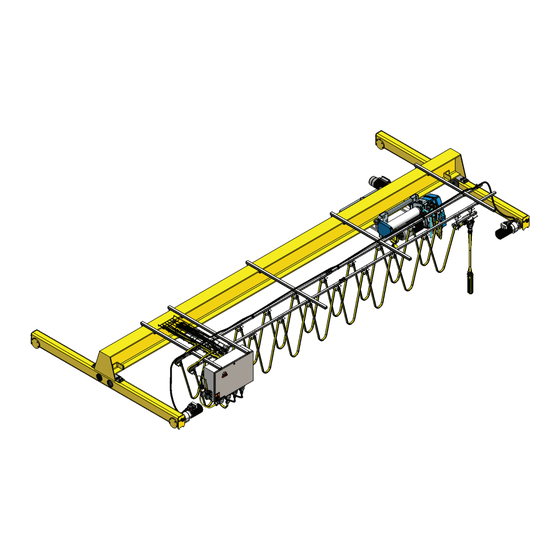
Page 35: A) Plan View
6.A) PLAN VIEW P/N: C11746308 REV. AB June 2022... -
Page 36: Step 1: Clamping Cross Arm & Control Box Support Rails
STEP 1: CLAMPING CROSS ARM & CONTROL BOX SUPPORT RAILS WARNING Check for any damage to the crane kit components during shipment. DO NOT install damaged crane kit components. STEP 2: SPACING FOR CROSS ARMS/SUPPORT RAILS P/N: C11746308 REV. AB June 2022... -
Page 37: Step 3: C-Rail Mounting
STEP 3: C-RAIL MOUNTING P/N: C11746308 REV. AB June 2022... -
Page 38: Step 4: C-Rail Joint Assembly
STEP 4: C-RAIL JOINT ASSEMBLY NOTICE It is the installer’s responsibility to assure that the crane assembly complies in total with all applicable local, state and national codes and standards including those mentioned herein. Crane wiring should be done by a licensed electrician and be in accordance with the National Electric Code (ANSI/NFPA 70). -
Page 39: Step 5: Mounting Bridge Panel
STEP 5: MOUNTING BRIDGE PANEL P/N: C11746308 REV. AB June 2022... -
Page 40: Step 6: End Stop Assembly
STEP 6: END STOP ASSEMBLY P/N: C11746308 REV. AB June 2022... -
Page 41: Step 7: Hoist Cable Assembly
STEP 7: HOIST CABLE ASSEMBLY P/N: C11746308 REV. AB June 2022... -
Page 42: Step 8: Control Pendant Cable Assembly
STEP 8: CONTROL PENDANT CABLE ASSEMBLY P/N: C11746308 REV. AB June 2022... -
Page 43: Yk/Sk Tow Arm
YK/SK TOW ARM STEP 9: TOW ARM KIT PREPARATION TOW ARM ADJUSTMENTS RIGHT ISO VIEW LEFT ISO VIEW P/N: C11746308 REV. AB June 2022... -
Page 44: Y80/800 Tow Arm
Y80/800 TOW ARM STEP 9: TOW ARM KIT PREPARATION TOW ARM ADJUSTMENTS RIGHT ISO VIEW LEFT ISO VIEW P/N: C11746308 REV. AB June 2022... -
Page 45: Step 10: Tow Arm Kit Installation - Yk/Sk
STEP 10: TOW ARM KIT INSTALLATION – YK/SK WARNING Alterations or modifi cations of equipment and use of non-factory repair parts can lead to dangerous operation and injury. TO AVOID INJURY: DO NOT alter or modify equipent. DO NOT use equipment to lift, support or otherwise transport people. -
Page 46: Step 10: Tow Arm Kit Installation - Y80/800
STEP 10: TOW ARM KIT INSTALLATION – Y80/800 P/N: C11746308 REV. AB June 2022... -
Page 47: Step 11: Cable Tray Installation
STEP 11: CABLE TRAY INSTALLATION NOTE: WIRE TRAY IS ONLY INCLUDED WITH YK/SK PRODUCTS P/N: C11746308 REV. AB June 2022... -
Page 48: Step 12: Placing Festoon Cables On Cable Tray
STEP 12: PLACING FESTOON CABLES ON CABLE TRAY NOTE: WIRE TRAY IS ONLY INCLUDED WITH YK/SK PRODUCTS P/N: C11746308 REV. AB June 2022... -
Page 49: Step 13: Festoon Cable Connection
STEP 13: FESTOON CABLE CONNECTION DANGER Disconnect power and lockout disconnecting means before connecting power supply to hoist. WARNING DO NOT UNPLUG CONNECTORS WHILE CIRCUIT IS ENERGIZED. BEFORE PLUGGING IN CONNECTORS REMOVE POWER FROM SYSTEM. P/N: C11746308 REV. AB June 2022... -
Page 50: Step 14: Push-Button Pendant Assembly
STEP 14: PUSH-BUTTON PENDANT ASSEMBLY WARNING DO NOT UNPLUG CONNECTORS WHILE CIRCUIT IS ENERGIZED. BEFORE PLUGGING IN CONNECTORS REMOVE POWER FROM SYSTEM. P/N: C11746308 REV. AB June 2022... -
Page 51: Step 15: Bridge Motor Cable Connection
STEP 15: BRIDGE MOTOR CABLE CONNECTION WARNING DO NOT UNPLUG CONNECTORS WHILE CIRCUIT IS ENERGIZED. BEFORE PLUGGING IN CONNECTORS REMOVE POWER FROM SYSTEM. P/N: C11746308 REV. AB June 2022... -
Page 52: Step 16: Bridge Tow Arm Installation
STEP 16: WARNING BRIDGE TOW ARM INSTALLATION The trolley frame and bridge frame shall not be considered electrically grounded through the DANGER bridge and trolley wheels and its respective Disconnect power and lockout tracks. A fourth runway conductor and disconnecting means before collector shall be provided for grounding. -
Page 53: Step 17: Bridge Travel Limit Switch Installation
STEP 17: BRIDGE TRAVEL LIMIT SWITCH INSTALLATION NOTE: BRIDGE TRAVEL LIMIT SWITCH ONLY WARNING INCLUDED WITH YK/SK PRODUCTS Damage to the hoist, a dropped load, and injury may result if limit switches fail due to improper use. Under normal operating conditions, stop hoist travel before engaging limit switches. -
Page 54: Step 18: Festoon Runway Checking
STEP 18: FESTOON RUNWAY CHECKING WARNING Make sure all INSTALLATIONS AND START-UP INSPECTIONS have been made in accordance with instructions furnished with the HOIST and TROLLEY before turning on the power. WARNING Trolley stops (clip angles) or end stop assemblies must be installed on both ends of the bridge beam to prevent hoist trolley from running off the end of the beam, which could result in injury to the operator and others and damage to the load and other property. -
Page 55: Radio Control & Horn Installation For Festoon System
CHAPTER 7 RADIO CONTROL & HORN INSTALLATION FOR FESTOON SYSTEM P/N: C11746308 REV. AB June 2022... -
Page 56: Step 1: Cross Arm & Bracket Installation For Radio Control
STEP 1: CROSS ARM & BRACKET INSTALLATION FOR RADIO CONTROL NOTE: MOUNTING BRACKET AND CROSS ARM ONLY INCLUDED WITH YK/SK PRODUCTS RADIO CONTROL SYSTEM BRACKET INSTALLATION P/N: C11746308 REV. AB June 2022... -
Page 57: Step 2: Radio Control System Installation
STEP 2: RADIO CONTROL SYSTEM INSTALLATION WARNING DO NOT UNPLUG CONNECTORS WHILE CIRCUIT IS ENERGIZED. BEFORE PLUGGING IN CONNECTORS REMOVE POWER FROM SYSTEM. P/N: C11746308 REV. AB June 2022... -
Page 58: Step 3: Horn Installation (Internal/External)
STEP 3: HORN INSTALLATION (INTERNAL/EXTERNAL) DANGER Disconnect power and lockout disconnecting means before installing internal or external horn. P/N: C11746308 REV. AB June 2022... - Page 59 NOTES: P/N: C11746308 REV. AB June 2022...
-
Page 60: Warranty
WARRANTY LIMITATION OF WARRANTIES, REMEDIES, AND DAMAGES INDEMNIFICATION AND SAFE OPERATION Buyer shall comply with and require its employees to comply with directions set C. IN NO EVENT SHALL SELLER BE LIABLE TO BUYER OR ANY THIRD forth in instructions and manuals furnished by Seller and shall use and require its PARTY WITH RESPECT TO ANY GOOD OR REPLACEMENT PART, employees to follow such instructions and manuals and to use reasonable care in WHETHER, IN CONTRACT, TORT OR OTHER THEORY OF LAW, FOR...