Table of Contents

Related Manuals for Broan B6LC


Summary of Contents for Broan B6LC
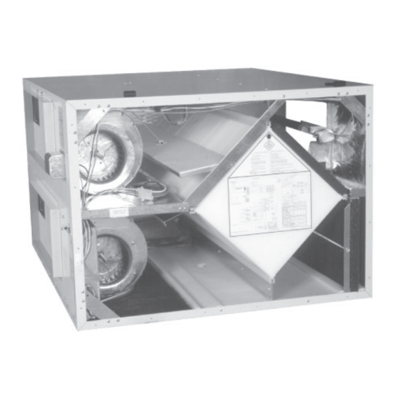
- Page 1 Light Commercial Heat Recovery Ventilators and Energy Recovery Ventilators Installation, Operation and Service Instructions INSTALLER: READ THESE INSTRUCTIONS AND LEAVE THIS MANUAL TO THE END USER. VB0002 B6LC VB0001 B12LC 22638 rev. F...
-
Page 2: Table Of Contents
Appendix F - Control Box Assembly B6LC and B12LC ....... .19... -
Page 3: Safety Considerations
1. Safety Considerations Hazards may exist within this equipment because it contains electrical and powerful moving components. Only qualifi ed service personnel should install or service this equipment. Untrained personnel can perform basic maintenance such as maintaining fi lters. Observe precautions marked in literature and on labels attached to unit. Follow all safety codes. Please take note that this manual uses the following symbols to emphasize particular information: WARNING Identifi es an instruction which, if not followed, might cause serious personal injuries including possibility of death. -
Page 4: Installation
2.4 Ductwork The supply and exhaust duct connections on the unit are as follows: UNIT DUCT SIZE B6LC 14” x 8” (356 mm x 203 mm) B12LC 20” x 8” (508 mm x 203 mm) NOTE: Duct sizes are for connection purposes only. Ducts should be sized to keep noise and pressure drop to a minimum. -
Page 5: Internal Grilles And Diffusers
Appendix C. All ports on the B6LC and B12LC units have 1” (25 mm) fl anges to facilitate the installation of the ductwork. Please note that the “Fresh Air from Outdoors” port has a defrost damper incorporated with it. -
Page 6: Controls
It is possible to extend the defrost times during very cold weather by removing the jumper JU1-F on the circuit board as shown in Appendix F. For dimension and weight changes to the B6LC and B12LC models with recirculation defrost, see Appendix B-2 and B-4. -
Page 7: Airfl Ow Measurements And Balancing
A medium effi ciency fi lter for the supply air stream is available from your supplier. This fi lter is disposable and should be replaced when it becomes dirty. VL0001 B6LC and B12LC units Washable foam fi lters ... -
Page 8: Annual Maintenance
5. Maintenance (cont’d) 5.2 Annual Maintenance WARNING Risk of electric shocks. Before performing maintenance or repairs, always stop the unit, then turn power off at service panel. The wearing of safety glasses and gloves is recommended when handling unit components to prevent injuries caused by sharp edges. -
Page 9: Troubleshooting
LOCKING PLATE TWO SCREWS CAPACITOR VD0004A B6LC and B12LC units 6.2 Troubleshooting WARNING The wearing of safety glasses and gloves is recommended since a few diagnosis procedures may require the unit to be in operation while proceeding. Be careful with moving and live parts to prevent injuries. -
Page 10: Service Parts
Core Defrost Actuator B6LC-B12LC Relay SPDT 120 VAC, 1 HP, Core Defrost Actuator B12LC, Powder SV500025914 SV63341 Coated 30 A @ 120 VAC, B6LC, B12LC SV63327 Core Damper B6LC Relay DPST 120 VAC, 1 HP, SV500025915 30 A @ 120 VAC, B6LC, B12LC... -
Page 11: B6Lc-B12Lc Recirculation Defrost
Core Aluminum B6LC-B12LC (unitary) Relay SPDT 120 VAC, 1 HP, SV1607787 ERV HM Core B6LC-B12LC (unitary) SV500025914 30 A @ 120 VAC, B6LC, B12LC SV201805 Filter SWF 13.125" x 11.25" x 1" (unitary) Relay DPST 120 VAC, 1 HP, SV63333... -
Page 12: Appendix A - Mounting Diagram
Appendix A MOUNTING DIAGRAM B6LC AND B12LC UNITS NOTE: Diagrams show standard unit configuration. Reinforced For units with the reversed door option, the Rubber Strap door will be located here. Recirculation Module (Factory Installed) 3/8" (10mm) Threaded Rod (Supplied by others) -
Page 13: Appendix B - Unit Dimensions
Appendix B UNIT DIMENSIONS B-1: B6LC (WITHOUT RECIRCULATION MODULE) - Page 14 Appendix B (cont’d) UNIT DIMENSIONS B-2: B6LC WITH RECIRCULATION MODULE (FACTORY INSTALLED)
- Page 15 Appendix B (cont’d) UNIT DIMENSIONS B-3: B12LC (WITHOUT RECIRCULATION MODULE)
- Page 16 Appendix B (cont’d) UNIT DIMENSIONS B-4: B12LC WITH RECIRCULATION MODULE (FACTORY INSTALLED)
-
Page 17: Appendix C - Balancing Dampers Position
Appendix C BALANCING DAMPERS POSITION Gravity Backdraft Damper (for recirculation defrost option only) Reverse Door Option Min.12" (305 mm) Exhaust Air to Outdoors Min. 8" (203 mm) (Optional) Canvas Vibration Isolator Fresh Air From Outdoors Fresh Air to Building Balancing Damper Exhaust Air From Building... -
Page 18: Appendix E - Terminal Control Diagrams
Appendix E TERMINAL CONTROL DIAGRAMS E-1: TERMINAL LABEL E-2: WALL CONTROL CONNECTION A low voltage remote control wiring interface is provided on One type of remote wall control is available: the Slide Switch Wall the unit. The connections for the low voltage remote wiring are Control with fan switch and dehumidistat control. -
Page 19: Appendix F - Control Box Assembly B6Lc And B12Lc
éviter l'interconnexion des sorties de Classe 2. sorties de Classe 2. sorties de Classe 2. VE0467A Appendix F CONTROL BOX ASSEMBLY B6LC AND B12LC Remote control access plate Remote wiring terminal block Control box Unit cabinet Control cover plate VE0001A... -
Page 20: Appendix G - Make-Up Heat Requirements
Appendix G MAKE-UP HEAT REQUIREMENTS B6LC B12LC... -
Page 21: Appendix H - Wiring Diagrams
• This product is equipped with an overload protection (fuse). A blown fuse indicates an overload or a short-circuit situation. If the fuse blows, disconnect the unit from its power source. Discontinue using the unit and contact technical support. B6LC, B12LC - Exhaust Defrost - Normal Low Speed SYSTEM DIAGRAM... - Page 22 • This product is equipped with an overload protection (fuse). A blown fuse indicates an overload or a short-circuit situation. If the fuse blows, disconnect the unit from its power source. Discontinue using the unit and contact technical support. B6LC, B12LC - Exhaust Defrost - Normal Low Speed (cont’d) LOGIC DIAGRAM...
- Page 23 • This product is equipped with an overload protection (fuse). A blown fuse indicates an overload or a short-circuit situation. If the fuse blows, disconnect the unit from its power source. Discontinue using the unit and contact technical support. B6LC, B12LC - Recirculation Defrost - Normal Low Speed SYSTEM DIAGRAM...
- Page 24 • This product is equipped with an overload protection (fuse). A blown fuse indicates an overload or a short-circuit situation. If the fuse blows, disconnect the unit from its power source. Discontinue using the unit and contact technical support. B6LC, B12LC - Recirculation Defrost - Normal Low Speed (cont’d) LOGIC DIAGRAM...