
Related Manuals for True UES900


Summary of Contents for True UES900
- Page 1 * Assembly Guide & Warranty Card Included ES900 UPRIGHT BIKE OWNER’S MANUAL Model # UES900 Revision 042722...
- Page 2 ES900 UPRIGHT BIKE OWNERS MANUAL IMPORTANT: All Products shown are prototype. Actual product delivered may vary. Product specifications, features & software are subject to change without notice. For the most up to date owner’s manual please visit www.truefitness.com. For documents in additional languages please visit www.truefitness.com/document-library/29/international-manuals IMPORTANTE: Todos los productos mostrados son prototipos.
- Page 3 The proud manufacturing tradition of quality and the culture of innovation at TRUE have given rise to a full line of extraordinary cardio and strength equipment. As a result, people all over the world are benefiting from the TRUE experience.
-
Page 4: Table Of Contents
ES900 UPRIGHT BIKE OWNERS MANUAL TABLE OF CONTENTS : Chapter 1: Safety Instructions Safety Instructions Space Requirements Grounding Instructions Power Requirements Warning Decals Compliances Chapter 2: Assembly Instructions Pre-Assembly Checklist Bike Assembly Steps Chapter 3: Product Overview Bike Overview Chapter 4: Care & Maintenance Care &... -
Page 5: Chapter 1: Safety Instructions
45, smokes, has high cholesterol, is obese or has not exercised regularly in the past year. Additionally, TRUE recommends consulting a fitness professional on the correct use of this product. - Page 6 Do not use this product outdoors, near water, while wet, or in areas if high humidity including extreme temperature changes • Never operate a TRUE product with the air openings blocked. Keep air openings free of lint, hair or any obstructing material. •...
-
Page 7: Space Requirements
SPACE REQUIREMENTS: • TRUE’s recommendation is to leave a 39” safety zone at rear of bike. The sides of the bike should be at least 20” away from the wall or obstructions. (See Fig 1) Truefitness.com / 800.426.6570 / 636.272.7100... -
Page 8: Grounding Instructions
CHAPTER 1: SAFETY INSTRUCTIONS GROUNDING INSTRUCTIONS: This product must be grounded, if it should malfunction or breakdown, grounding provides a path of least resistance for electric current to reduce the risk of electric shock. This product is equipped with a cord having an equipment-grounding conductor and a grounding plug. -
Page 9: Power Requirements
CHAPTER 1: SAFETY INSTRUCTIONS Truefitness.com / 800.426.6570 / 636.272.7100... -
Page 10: Warning Decals
CHAPTER 1: SAFETY INSTRUCTIONS WARNING DECALS: WARNING: Replace warning labels that may be worn, damaged or missing. To replace any worn or missing warning decals contact TRUE FITNESS by one of the following: www.truefitness.com or contact customer service at 800-883-8783. COMPLIANCES: This equipment complies with all applicable codes and regulations. -
Page 11: Chapter 2: Assembly Instructions
All exercise equipment is potentially hazardous. If attention is not paid to the conditions of equipment usage, death, or serious injury could occur. • Save these instructions. *Should you need technical assistance in assembly of your TRUE Fitness product, contact TRUE Fitness Technical Support at 1-800-883-8783. PRE-ASSEMBLY CHECK LIST: Provided Tools:... - Page 12 CHAPTER 2: ASSEMBLY INSTRUCTIONS PRE-ASSEMBLY CHECK LIST (continued): Provided Hardware: 1 & 2 (F & R 5 (F RONT TABILIZER RONT 6 (M 11 (S TORAGE 8 (H 12 (C ANDLEBAR ONSOLE OVERS Truefitness.com / 800.426.6570 / 636.272.7100...
- Page 13 CHAPTER 2: ASSEMBLY INSTRUCTIONS PRE-ASSEMBLYCHECKLIST(continued): Provided hardware: Step 16 (Tablet Holder) Pan Head Phillips Screw M4 Truefitness.com / 800.426.6570 / 636.272.7100...
- Page 14 CHAPTER 2: ASSEMBLY INSTRUCTIONS PRE-ASSEMBLY CHECK LIST (continued): Additional Items Provided: POLAR T34 Transmitter and Chest Strap (Heart Rate Monitor) Power Adaptor NOTE: For the 9” Touchscreen Console, a different 12V, 3A Power Adaptor is provided with the console packaging. NOTE: For the Orange LED Console, use the 9V, 1.3A Power Adaptor provided with the base unit.
-
Page 15: Bike Assembly Steps
CHAPTER 2: ASSEMBLY INSTRUCTIONS BIKE ASSEMBLY STEPS: CAUTION: • Use caution when assembling bike. It is recommended that at least two people unpack and assemble bike. • Remove all bike components from packaging. • For each step use hardware in the corresponding bag •... - Page 16 CHAPTER 2: ASSEMBLY INSTRUCTIONS BIKE ASSEMBLY STEPS (continued): Step 1: Rear Stabilizer Bar: a) Rotate the frame forward on the Front Stabilizer bracket (metal). *At least one person should hold the frame, while another person completes the remaining Rear Stabilizer installation steps b) For each screw, install through split washer then flat washer c) Insert Rear Stabilizer into the metal bracket...
- Page 17 CHAPTER 2: ASSEMBLY INSTRUCTIONS BIKE ASSEMBLY STEPS (continued): Step 2: Front Stabilizer Bar (continued): b) For each screw, install through split washer then flat washer c) Insert Front Stabilizer into the metal bracket Install each screw through the bottom of the metal bracket, then through the Front Stabilizer d) Tighten using the provided hex wrench Hardware Required:...
- Page 18 CHAPTER 2: ASSEMBLY INSTRUCTIONS BIKE ASSEMBLY STEPS (continued): Step #4 Front Mast Cable Routing: a) Pull the cable bundle coming from the base of the unit through the front mast using the pull tie provided with the mast. Pull Tie Step #5 Front Mast: a) For each screw, install through split washer then flat washer...
- Page 19 CHAPTER 2: ASSEMBLY INSTRUCTIONS BIKE ASSEMBLY STEPS (continued): Step #6 Mast Boot: a) Pull down the Mast Boot b) Attach the Mast Boot to the plastic shrouds by tightening both screws with a Phillips head screwdriver (not provided). Hardware Required: 2 M4 x 10 Screws Step 7: Handlebar Cables a) While at least one person holds the...
- Page 20 CHAPTER 2: ASSEMBLY INSTRUCTIONS BIKE ASSEMBLY STEPS (continued): Step #9 Console Mounting: a) Align the back of the Console with the Front Mast Console Mounting Plate b) Attach the Console to the Mounting Plate by tightening all 4 screws with a Phillips head screwdriver (not provided).
- Page 21 CHAPTER 2: ASSEMBLY INSTRUCTIONS BIKE ASSEMBLY STEPS (continued): Step #10 Console Cable Connections (continued): Orange LED Console NOTE: Ethernet cable connection is not available on the Orange LED Console Truefitness.com / 800.426.6570 / 636.272.7100...
- Page 22 CHAPTER 2: ASSEMBLY INSTRUCTIONS ASSEMBLY STEPS (continued): Step 13 Console Cable Connections (continued): 9” Touch Console Connect to 4-pin connector Connect to 6-pin connector Connect to 5-pin connector Ground connector (see next page) Insert brake servo white 7- pin connector DO NOT insert SD55 black 7-pin connector...
- Page 23 CHAPTER 2: ASSEMBLY INSTRUCTIONS BIKE ASSEMBLY STEPS (continued): Step #11 Storage Tray: a) Insert the Storage Tray on top of the Front Mast Mounting Plate; pay special attention to make sure that the plastic lip of the Storage Tray is tucked underneath the bottom of the Console b) Attach the Storage Tray to the Mounting Plate by tightening all 4 screws with a Phillips...
- Page 24 CHAPTER 2: ASSEMBLY INSTRUCTIONS BIKE ASSEMBLY STEPS (continued): Step 13: Pedals: a) Align the Left Pedal with the Left Crank and the Right Pedal with the Right Crank; pedals should be clearly labeled on the Pedal Strap b) Secure each pedal to the appropriate crank using the provided wrench NOTE: The left pedal is reverse-threaded (turn counter-clockwise to tighten)
- Page 25 CHAPTER 2: ASSEMBLY INSTRUCTIONS BIKE ASSEMBLY STEPS (continued): Step 16 Attach Tablet Holder to Console: • Attach the two t-shaped bottom connectors on the tablet holder to the back of the console as shown. • Secure the tablet holder to the back of the console by fastening the M4 screws (quantity 2) in the predefined holes as shown using a Philips Head...
- Page 26 CHAPTER 2: ASSEMBLY INSTRUCTIONS BIKE ASSEMBLY STEPS (continued): Wiring Diagram: Truefitness.com / 800.426.6570 / 636.272.7100...
-
Page 27: Chapter 3: Product Overview
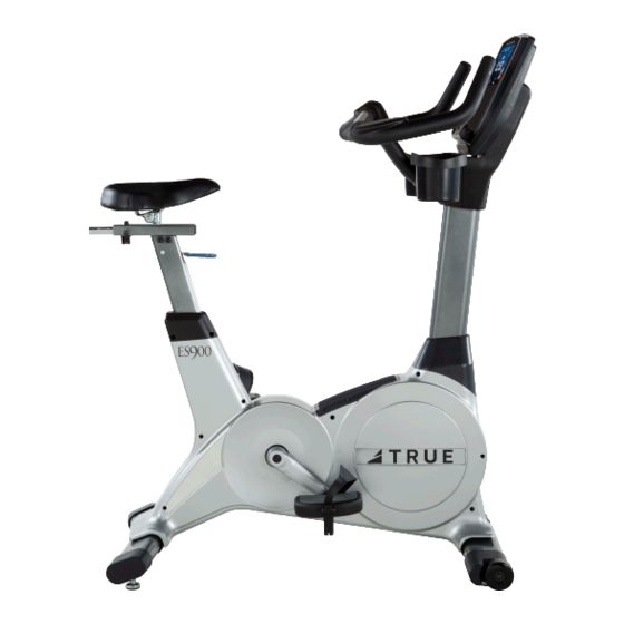
CHAPTER 3: PRODUCT OVERVIEW UPRIGHT BIKE OVERVIEW: Console Assembly Contact Heart Rate Pads Seat Adjustment Bottle Holder Handles Ethernet Port Power Cord Pedals Leveling Feet Truefitness.com / 800.426.6570 / 636.272.7100... - Page 28 CHAPTER 3: PRODUCT OVERVIEW UPRIGHT BIKE OVERVIEW (continued): Console Assembly: The Touchscreen console allows the user to set up a workout program and control the bike during a workout. Contact Heart Rate Pads: Allows the user to check their heart rate without wearing a wireless chest strap. Bottle Holder: Holds an average size drink bottle for convenient use during a workout.
-
Page 29: Chapter 4: Care & Maintenance
It is important to perform the minor maintenance tasks described in this section. Failure to maintain the bike as described here could void the TRUE Fitness Warranty. To reduce the risk of electrical shock, always unplug the unit from its power source before cleaning or performing any maintenance tasks. -
Page 30: Other Scheduled Preventive Maintenance
CHAPTER 4: CARE & MAINTENANCE OTHER SCHEDULED PREVENTIVE MAINTENANCE: TRUE recommends that yearly scheduled maintenance be performed by a qualified service technician. Please contact your dealer or visit www.truefitness.com to contact a local TRUE authorized service technician. Scheduled Preventive Maintenance: •... -
Page 31: Chapter 5: Customer Service
HOURS OF OPERATION: 8:30 A.M. - 5:00 P.M. CST E-MAIL: service@truefitness.com CONTACTING SALES: Interested in TRUE Products? Please contact us with any sales or product inquires so that we may direct you to the appropriate sales representative to answer your questions. TRUE FITNESS HOME OFFICE 865 HOFF ROAD ST. -
Page 32: Reporting Freight Claims Or Parts Damage
Severe Damage: Obvious damage to external packaging / internal product. Please refuse the shipment and it will be returned to TRUE Fitness by the carrier. Contact the TRUE Fitness customer support team by calling 800.883.8783 or sales support team by calling 800.426.6570 Monday-Friday during normal business hours to notify us that the shipment has been refused. -
Page 33: Chapter 6: Additional Information
This troubleshooting guide is intended to assist in diagnostics only and is not all inclusive. Technical specifications, error codes and programming are subject to change without notice. TRUE accepts no liability for any damage or loss suffered by persons whom rely wholly or in part on any description or statement contained within this manual. Please visit www.truefitness.com to obtain the most recent version of all manuals and contact the TRUE Service Department at 800-... - Page 34 CHAPTER 6: ADDITIONAL INFORMATION TROUBLESHOOTING GUIDE (continued): The battery inside the transmitter Replace the transmitter belt with a compatible belt is depleted transmitter belt Another user wearing a Move the units so that there is more space in-between units compatible transmitter strap is within 3 foot (1 meter) of the unit Heart rate is Environmental interference from...
-
Page 35: Warranty Information
Doing so may void the expressed warranty. TRUE Limited Warranty service may be obtained by contacting the authorized TRUE dealer from whom the Product was purchased. If the Frame dealer from whom the Product was purchased is no longer an... - Page 36 Registration Form is completed on-line; or if the attached form is NOTE TO AUTHORIZED WARRANTY LABOR PROVIDERS: filled in, signed by the original purchaser and mailed to TRUE Warranty labor reimbursement or warranty parts rights may not within 30 days of purchaser’s receipt of this Product. The serial...
- Page 37 Residential Limited Warranty ES900 Upright Bikes Thank you for purchasing a TRUE product. To validate the TRUE product warranty the fast and easy way, please go online now to www.truefitness.com and register your product. The information you provide will never be distributed to any other individuals or agencies for any purpose. If you prefer to mail your warranty card, have the owner of the product complete the information below and return it to TRUE Fitness Technology within 30 days from the date of equipment installation.