
Related Manuals for True RES900


Summary of Contents for True RES900
- Page 1 * Assembly Guide & Warranty Card Included RES900 RECUMBENT BIKE OWNER’S MANUAL Model # RES900-17 Revision 122316...
- Page 2 ES900 RECUMBENT BIKE OWNERS MANUAL IMPORTANT: All Products shown are prototype. Actual product delivered may vary. Product specifications, features & software are subject to change without notice. For the most up to date owner’s manual please visit www.truefitness.com. For documents in additional languages please visit www.truefitness.com/document-library/29/international-manuals IMPORTANTE: Todos los productos mostrados son prototipos.
- Page 3 The proud manufacturing tradition of quality and the culture of innovation at TRUE have given rise to a full line of extraordinary cardio and strength equipment. As a result, people all over the world are benefiting from the TRUE experience.
-
Page 4: Table Of Contents
ES900 RECUMBENT BIKE OWNERS MANUAL TABLE OF CONTENTS: Chapter 1: Safety Instructions Chapter 5: Care & Maintenance Safety Instructions Care & Maintenance Space Requirements Cleaning the Equipment Grounding Instructions Leveling the Unit Power Requirements Lubrication Warning Decals Other Scheduled Preventive Maintenance Compliances Long Term Storage Chapter 2 Assembly Instructions... -
Page 5: Chapter 1: Safety Instructions
45, smokes, has high cholesterol, is obese or has not exercised regularly in the past year. Additionally, TRUE recommends consulting a fitness professional on the correct use of this product. - Page 6 Do not use this product outdoors, near water, while wet, or in areas if high humidity including extreme temperature changes • Never operate a TRUE product with the air openings blocked. Keep air openings free of lint, hair or any obstructing material. •...
-
Page 7: Space Requirements
SPACE REQUIREMENTS: • TRUE’s recommendation is to leave a 39” safety zone at rear of bike. The sides of the bike should be at least 20” away from the wall or obstructions. (See Fig 1) Truefitness.com / 800.426.6570 / 636.272.7100... -
Page 8: Grounding Instructions
CHAPTER 1: SAFETY INSTRUCTIONS GROUNDING INSTRUCTIONS: This product must be grounded, if it should malfunction or breakdown, grounding provides a path of least resistance for electric current to reduce the risk of electric shock. This product is equipped with a cord having an equipment-grounding conductor and a grounding plug. - Page 9 CHAPTER 1: SAFETY INSTRUCTIONS Truefitness.com / 800.426.6570 / 636.272.7100...
-
Page 10: Warningdecals
CHAPTER 1: SAFETY INSTRUCTIONS WARNINGDECALS: WARNING: Replace warning labels that may be worn, damaged or missing. To replace any worn or missing warning decals contact TRUE FITNESS by one of the following: www.truefitness.com or contact customer service at 800-883-8783. COMPLIANCES: This equipment complies with all applicable codes and regulations. -
Page 11: Chapter 2 Assembly Instructions
All exercise equipment is potentially hazardous. If attention is not paid to the conditions of equipment usage, death, or serious injury could occur. • Save these instructions. *Should you need technical assistance in assembly of your TRUE Fitness product, contact TRUE Fitness Technical Support at 1-800-883-8783. PRE-ASSEMBLY CHECK LIST: Provided Tools:... - Page 12 CHAPTER 2: ASSEMBLY INSTRUCTIONS PRE-ASSEMBLYCHECKLIST(continued): Provided hardware: 1 & 2 (F & R 4 (S RONT TABILIZER ANDLEBAR Counter-bore Hex Screw, M8xL20 Hex Screw, M10xL55 (C4) Qty. 4 (X1) Qty. 4 Hex Screw, M8xL20 Split Washer, M10 (X4) Qty. 2 (S1) Qty.
- Page 13 CHAPTER 2: ASSEMBLY INSTRUCTIONS PRE-ASSEMBLYCHECKLIST(continued): Provided hardware: Step 16 (Tablet Holder) Pan Head Phillips Screw M4 Truefitness.com / 800.426.6570 / 636.272.7100...
- Page 14 CHAPTER 2: ASSEMBLY INSTRUCTIONS PRE-ASSEMBLY CHECK LIST (continued): Additional Items Provided: POLAR T34 Transmitter and Chest Strap (Heart Rate Monitor) Truefitness.com / 800.426.6570 / 636.272.7100...
-
Page 15: Assembly Steps
CHAPTER 2: ASSEMBLY INSTRUCTIONS ASSEMBLY STEPS: CAUTION: • Use caution when assembling bike. It is recommended that at least two people unpack and assemble bike. • Remove all bike components from packaging. • For each step use hardware in the corresponding bag Sub-Assembly Identification: Use the image below as a reference for where the provided sub-assemblies will be located in the complete bike assembly: Truefitness.com / 800.426.6570 / 636.272.7100... - Page 16 CHAPTER 2: ASSEMBLY INSTRUCTIONS ASSEMBLY STEPS (continued): Step 1 & 2 Frontand Rear Stabilizer Bars: CAUTION: • It is recommended that at least 2 people are used to assemble the bike. • To protect the floor from damage, rest the bike frame on a large piece of cardboard packaging. •...
- Page 17 CHAPTER 2: ASSEMBLY INSTRUCTIONS ASSEMBLY STEPS (continued): Step 3 Seat Handlebar Cable Connections: • Prior to connection, verify the handlebar is in the correct orientation; graphics on the contact heart rate thumb switches should be facing up • Connect the handlebar cables, as shown by the connection lines in the provided diagrams (above, left) Step 4 Seat Handlebar Assembly: •...
- Page 18 CHAPTER 2: ASSEMBLY INSTRUCTIONS ASSEMBLY STEPS (continued): Step 5 Seat Back Frame Assembly: • Install the seat back frame into the seat carriage • For each hex screw (X5, quantity 8), install through quantity 1 split washer (S5), followed by quantity 1 flat washer (F5) •...
- Page 19 CHAPTER 2: ASSEMBLY INSTRUCTIONS ASSEMBLY STEPS (continued): Step 6 Rear Seat Pivot Cover Assembly: • Install the Rear Seat Pivot Cover onto the Seat Carriage • Rear Seat Pivot Cover should mate cleanly with the Front Seat Pivot Cover (as shown, above) •...
- Page 20 CHAPTER 2: ASSEMBLY INSTRUCTIONS ASSEMBLY STEPS (continued): Step 8 Pedal Assembly: • Align the left pedal with the left crank, and the right pedal with the right crank (pedals should be clearly labeled on the pedal strap) • Secure each pedal to the appropriate crank using the provided pedal wrench NOTE: The left pedal is reverse-threaded...
- Page 21 CHAPTER 2: ASSEMBLY INSTRUCTIONS ASSEMBLY STEPS (continued): Step 10 Front Mast Cable Connections: • At least 1 person should hold the Front Mast while an additional person(s) routes the Front Mast Cables. • Route the bundle of cables through the Front Mast, as shown in the provided image (left).
- Page 22 CHAPTER 2: ASSEMBLY INSTRUCTIONS Step 11 Front Mast Assembly: • Install the front mast onto the bike frame; the short bracket on the bike frame should fit inside the front mast tube • Verify that the front mast is in the correct orientation; the storage dock compartments and front mast handlebars should be facing the seat assembly •...
- Page 23 CHAPTER 2: ASSEMBLY INSTRUCTIONS ASSEMBLY STEPS (continued): Step 13 Console Cable Connections (continued): 9” Touch Console Connect to 4-pin connector Connect to 6-pin connector Connect to 5-pin connector Ground connector (see next page) Insert Chihua white 8-pin connector DO NOT insert SD55 black 7-pin connector All ground wires...
- Page 24 CHAPTER 2: ASSEMBLY INSTRUCTIONS ASSEMBLY STEPS (continued): Step 14 Console Ground Connection: • Locate the ground screw; pre-installed into the grounding hole on the front mast console bracket • Remove the ground screw with a Phillips Head screwdriver (not provided) •...
- Page 25 CHAPTER 2: ASSEMBLY INSTRUCTIONS ASSEMBLY STEPS (continued): Step 16 Attach Tablet Holder to Console • Attach the two t-shaped bottom connectors on the tablet holder to the back of the console as shown. • Secure the tablet holder to the back of the console by fastening the M4 screws (quantity 2) in the predefined holes as shown using a Philips Head...
- Page 26 CHAPTER 2: ASSEMBLY INSTRUCTIONS ASSEMBLY STEPS (continued): Unit Leveling (if necessary): Turn feet (4x, located on the front and rear stabilizer) to adjust the levelness of the unit. Final Unit Connections: Truefitness.com / 800.426.6570 / 636.272.7100...
- Page 27 CHAPTER 2: ASSEMBLY INSTRUCTIONS ASSEMBLY STEPS (continued): Seat Bottom Adjustment (if necessary): The following information discusses the adjustability of the seat bottom position relative to the mesh seat back. Threaded seat bottom holes used for the “Back” position “Back” position The default seat bottom position is towards the back, creating a minimal amount of space between the seat bottom and the mesh seat back.
-
Page 28: Chapter 3: Product Overview
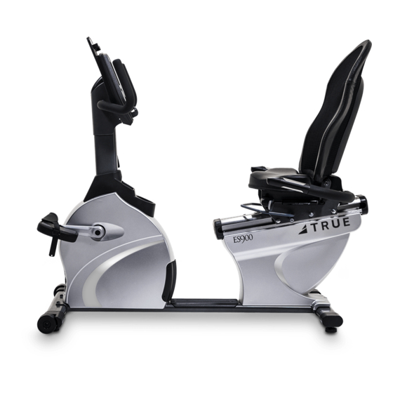
CHAPTER 3: PRODUCT OVERVIEW RECUMBENT BIKE OVERVIEW: Console Assembly Contact Heart Rate Pads Quick Access Keys Bottle Holder Battery Charge Port Seat Adjustment Pedals Leveling Feet Truefitness.com / 800.426.6570 / 636.272.7100... -
Page 29: Bottle Holder
CHAPTER 3: PRODUCT OVERVIEW RECUMBENT BIKE OVERVIEW (CONTINUED): Console Assembly: The Touchscreen console allows the user to set up a workout program and control the bike during a workout. Contact Heart Rate Pads: Allows the user to check their heart rate without wearing a wireless chest strap. Bottle Holder: Holds an average size drink bottle for convenient use during a workout. -
Page 30: Chapter 4: Programming & Operation Heart Rate Monitoring
HEART RATE CONTROL (HRC): Introduction: You are now the owner of the most sophisticated Heart Rate Control equipment available. TRUE HRC is unique and patented. It accommodates users from rehabilitation to world class athletes, and all those in between. TRUE HRC allows users to do a completely adjustment free heart rate controlled workout. -
Page 31: Target Heart Rate
HEART RATE CONTROL (continued): The TRUE HRC system is unique because users must enter the key parameters of the workout; target heart rate, weight, age, and time, prior to beginning the HRC workout. As users approach their target heart rate, the bike’s computer takes full control over the workout and changes the workout intensity automatically to keep users near their target heart rate. -
Page 32: Program Descriptions
CHAPTER 4: PROGRAMMING & OPERATION PROGRAM DESCRIPTIONS: Available programs vary depending on the console selected. Please refer to the chart below for assistance in determining which programs are available on this unit. 9” Touchscreen Console Quick Start: ** A workout in which the user controls all settings. The workout continues until it is ended by the user Manual: ** Users enter their weight, workout time or distance. -
Page 33: Calorie Goal
CHAPTER 4: PROGRAMMING & OPERATION PROGRAM DESCRIPTIONS (CONTINUED): Glute Buster: ** A changing WORKLOAD profile simulates hilly terrain to promote intense glute muscle use. Calorie Goal: ** This workout allows users to choose the number of calories they wish to burn within a specified workout time. The WORKLOAD will adjust automatically to attain this goal. - Page 34 CHAPTER 4: PROGRAMMING & OPERATION PROGRAM DESCRIPTIONS (continued): HRC Cruise Control: ** While in any program, Cruise Control will allow the user to set current heart rate as target heart rate by pressing a single button. The Cruise Control program takes control of WORKLOAD to maintain the users target Heart Rate. If Beats Per Minute exceeds the target by more than 12 BPM the workout will end and Cool Down will begin.
- Page 35 CHAPTER 4: PROGRAMMING & OPERATION Warning Decal Touchscreen Display Touchscreen Overview: Reading Rack Headphone Jack USB Port Truefitness.com / 800.426.6570 / 636.272.7100...
- Page 36 CHAPTER 4: PROGRAMMING & OPERATION Touchscreen Overview (continued): Touchscreen Display: Used to monitor or control a work out and for feature navigation. GO Quick Start: Allows the user to begin a Quick Start workout or preset workout. Reading Rack: A ledge on the console can be used to hold a book, magazine, e-reader, or tablet computer during a workout. USB Port: Allows users to export workout data to an external USB drive or update the console software.
-
Page 37: Console Navigation
CHAPTER 4: PROGRAMMING & OPERATION CONSOLE NAVIGATION: Home Screen: The Home Screen is displayed on the console when there is no workout in progress. From this screen the user is able to select from various options to begin a workout. A) GO Quick Start Starts a Quick Start workout in which the user controls all settings until the workout is ended. -
Page 38: Console Navigation
OPERATION CHAPTER 4: PROGRAMMING & CONSOLE NAVIGATION (continued): Selecting a Preset Workout: Access preset workouts by touching Workout Finder on the home screen. View the workouts by using the scroll bar (A) to sweep up and down the selection list, highlight the desired workout, and touch Next (B) to select it. Touching the "i"... - Page 39 CHAPTER 4: PROGRAMMING & OPERATION CONSOLE NAVIGATION (continued): Workout Data Screens: During any workout, a Workout Data Screen will be displayed to give the user a comprehensive visual overview of their current workout data. A) Calories / METS Display: D) Heart Rate: Shows the user’s heart rate in a digital beats per minute During the workout, this display will alternately show the (BPM) readout.
- Page 40 OPERATION CHAPTER 4: PROGRAMMING & CONSOLE NAVIGATION (continued): Workout Data Screen Controls: The Workout Data Screens contain various controls that allow users to adjust workout settings and to customize their overall workout experience. • A) Change View: There are three Workout Data Screen views available. Switch between the screens by touching the center of the display. Linear Graphic Lap Track Time Elapsed...
- Page 41 CHAPTER 4: PROGRAMMING & OPERATION CONSOLE NAVIGATION (continued): • D) Source: For Bluetooth Audio and to pair a mobile device with the console name on the screen. The user is given control over volume adjustments, mute and channel navigation. • E) Show Tools: Touching the "Show Tools"...
- Page 42 CHAPTER 4: PROGRAMMING & OPERATION CONSOLE NAVIGATION (continued): • F) Stop / Pause: The "Stop Pause" button allows the user to pause the current workout or stop it altogether and begin a two minute cool- down. Workout Summary Screen: At the end of a workout the Summary Screen will display an overview of the workout data (A). The workout data can be exported to another device through the Bluetooth connection.
-
Page 43: Advanced Console Functions
Entering Service Mode can be completed by touching and holding the upper left section of the screen (A) for 3-5 seconds or until the TRUE logo begins to blink. Then touch and hold the “Workout Finder” icon (B) until "Service"... -
Page 44: Advanced Console Functions
CHAPTER 4: PROGRAMMING & OPERATION ADVANCED CONSOLE FUNCTIONS (continued): Summary Screen: The Summary Screen provides an overview of the unit’s current settings (values cannot be changed in this screen). A) Product Model: The model number that the console is currently configured to. B) Software Version: The current version of software that is installed on the console. -
Page 45: Truefitness.com / 800.426.6570 / 636.272.7100
Utilities Menu - Product Setup: The product setup screen allows for adjustments to be made to the model configuration, TRUE’s recommendation is to only use the Setup Wizard to adjust these attributes. After touching the Setup Wizard Selection button (A), simply... -
Page 46: Truefitness.com / 800.426.6570 / 636.272.7100
ADVANCED CONSOLE FUNCTIONS (continued): Utilities Menu - Software Update: TRUE may periodically release software updates to ensure users enjoy the best workout experience available. Due to the complex nature of this procedure, it is recommended that any software update be completed by a TRUE certified service professional. -
Page 47: Truefitness.com / 800.426.6570 / 636.272.7100
CHAPTER 4: PROGRAMMING & OPERATION ADVANCED CONSOLE FUNCTIONS (continued): Options Menu: The options menu contains 12 Settings with various options available for each. To navigate the options menu, use the scroll selection buttons (A) to highlight the option to be changed and use the Workload keys to adjust the options. Once the changes are complete, press the back selection button (B) and the changes will be automatically saved. -
Page 48: Truefitness.com / 800.426.6570 / 636.272.7100
CHAPTER 4: PROGRAMMING & OPERATION ADVANCED CONSOLE FUNCTIONS (continued): Options Menu (continued): Max Workout Time: This setting will limit the amount of time that all workouts can last. By choosing the “Off” setting, the time will be unlimited (this setting does not apply to manual workouts or distance workouts). Finder Timeout: Choose how long the Workout Finder remains on the screen without any user interaction. - Page 49 CHAPTER 4: PROGRAMMING & OPERATION ADVANCED CONSOLE FUNCTIONS (continued): Diagnostics Menu - Calibration/Test & Production Test: These menus are currently not used on bikes or ellipticals. Diagnostics Menu - Error Log: Error codes are an important part of troubleshooting any issues with the unit. Any time an error occurs it is entered into the error log for review by a service professional.
-
Page 50: Truefitness.com / 800.426.6570 / 636.272.7100
CHAPTER 4: PROGRAMMING & OPERATION ADVANCED CONSOLE FUNCTIONS (continued): Statistics: An overview that includes distance, time, manual program count, preset program count, and apple device connections. These statistics can be exported to a connected USB drive by using the scroll selection buttons (A) to highlight the USB Export option and selecting the Enter button (B). -
Page 51: Chapter 5: Care & Maintenance
It is important to perform the minor maintenance tasks described in this section. Failure to maintain the bike as described here could void the TRUE Fitness Warranty. To reduce the risk of electrical shock, always unplug the unit from its power source before cleaning or performing any maintenance tasks. -
Page 52: Lubrication
*Note the user’s left side pedal is reverse threaded* OTHER SCHEDULED PREVENTIVE MAINTENANCE: TRUE recommends that yearly scheduled maintenance is to be performed by a qualified service technician. Please contact your dealer or visit www.truefitness.com to contact a TRUE local authorized service technician. -
Page 53: Chapter 6: Customer Service
HOURS OF OPERATION: 8:30 A.M. - 5:00 P.M. CST E-MAIL: service@truefitness.com CONTACTING SALES: Interested in TRUE Products? Please contact us with any sales or product inquires so that we may direct you to the appropriate sales representative to answer your questions. TRUE FITNESS HOME OFFICE 865 HOFF ROAD ST. -
Page 54: Reporting Freight Claims Or Parts Damage
Severe Damage: Obvious damage to external packaging / internal product. Please refuse the shipment and it will be returned to TRUE Fitness by the carrier. Contact the TRUE Fitness customer support team by calling 800.883.8783 or sales support team by calling 800.426.6570 Monday-Friday during normal business hours to notify us that the shipment has been refused. -
Page 55: Chapter 7: Additional Information
This troubleshooting guide is intended to assist in diagnostics only and is not all inclusive. Technical specifications, error codes and programming are subject to change without notice. TRUE accepts no liability for any damage or loss suffered by persons whom rely wholly or in part on any description or statement contained within this manual. Please visit www.truefitness.com to obtain the most recent version of all manuals and contact the TRUE Service Department at 800-... - Page 56 CHAPTER 7: ADDITIONAL INFORMATION TROUBLESHOOTING GUIDE (continued): The battery inside the transmitter replace the transmitter belt with a compatible transmitter belt is depleted belt Another user wearing a compatible transmitter strap is Move the units so that there is more space in-between units within 3 foot (1 meter) of the unit Heart rate is Environmental interference from...
- Page 57 The TRUE E'S900 Recumbent Bike 1s bnlliilntly engineered for comfort, safety and ef/1ciPncy. The self-generating bike now includes the latest technology available on TRUE products. The 9" touchscreen allows up to six custom profiles so everyone can sav;:. their own workouts. The latest 1n app tracking technology lets your entire...
- Page 59 Doing so may void the expressed warranty. TRUE Limited Warranty service may be obtained by contacting the authorized TRUE dealer from whom the Product was purchased. If the Frame dealer from whom the Product was purchased is no longer an...
- Page 60 Registration Form is completed on-line; or if the attached form is NOTE TO AUTHORIZED WARRANTY LABOR PROVIDERS: filled in, signed by the original purchaser and mailed to TRUE Warranty labor reimbursement or warranty parts rights may not within 30 days of purchaser’s receipt of this Product. The serial...
-
Page 61: Warranty Information
Residential Limited Warranty ES900 Upright Bikes Thank you for purchasing a TRUE product. To validate the TRUE product warranty the fast and easy way, please go online now to www.truefitness.com and register your product. The information you provide will never be distributed to any other individuals or agencies for any purpose. If you prefer to mail your warranty card, have the owner of the product complete the information below and return it to TRUE Fitness Technology within 30 days from the date of equipment installation.