Table of Contents
Advertisement
Quick Links
Advertisement
Table of Contents

Related Manuals for Icom IC-M422


Summary of Contents for Icom IC-M422
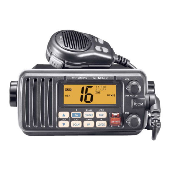
- Page 1 INSTRUCTION MANUAL VHF MARINE TRANSCEIVER iM422...
-
Page 2: Important
We want to take a couple of moments of your time to thank you for making the IC-M422 your radio of choice, and hope you agree with Icom’s philosophy of “technology first.” Many hours of research and development went into the design of your IC-M422. -
Page 3: In Case Of Emergency
IN CASE OF EMERGENCY If your vessel requires assistance, contact other vessels and the Coast Guard by sending a Distress call on Channel 16. USING CHANNEL 16 DISTRESS CALL PROCEDURE 1. “MAYDAY MAYDAY MAYDAY.” 2. “THIS IS ...” (name of vessel) 3. -
Page 4: Radio Operator Warning
RADIO OPERATOR WARNING Icom requires the radio operator to meet the FCC Requirements for Radio Frequency Expo- sure. An omnidirectional antenna with gain not greater than 9 dBi must be mounted a minimum W ARN ING of 5 meters (measured from the lowest point of the antenna) vertically above the main deck and all possible personnel. -
Page 5: Table Of Contents
TABLE OF CONTENTS FOREWORD ……………………………… i IMPORTANT ……………………………… i EXPLICIT DEFINITIONS ………………… i IN CASE OF EMERGENCY …………… ii NOTE ……………………………………… ii RADIO OPERATOR WARNING………… iii TABLE OF CONTENTS ………………… iv PRECAUTIONS ………………………… v 1 OPERATING RULES ………………… 1 2 PANEL DESCRIPTION …………… 2–4 I Front panel …………………………... -
Page 6: Precautions
This may pose a fire hazard or result in an electric shock. CAUTION: Changes or modifications to this device, not ex- pressly approved by Icom Inc., could void your authority to operate this device under FCC regulations. NEVER connect the transceiver to a power source of more than 16 V DC or use reverse polarity. -
Page 7: Operating Rules
D D PRIORITIES • Read all rules and regulations pertaining to priorities and keep an up-to-date copy handy. Safety and Distress calls take priority over all others. • You must monitor Channel 16 when you are not operating on another channel. •... -
Page 8: Panel Description
PANEL DESCRIPTION I Front panel Speaker q CHANNEL 16/CALL CHANNEL KEY [16• ➥ Push to select Channel 16. (p. 5) ➥ Push for 1 sec. to select Call channel. (p. 5) • “CALL” appears when Call channel is selected. ➥ Push for 3 sec. to enter Call channel programming con- dition when Call channel is selected. -
Page 9: I Microphone
i PUBLIC ADDRESS/RX SPEAKER KEY [PA• ➥ Push to turn the Public Address mode ON or OFF. (p. 31) ➥ Push for 1 sec. to turn the RX Speaker mode ON or OFF. (p. 31) o SCAN KEY [SCAN• ] (p. 11) ➥... -
Page 10: I Function Display
PANEL DESCRIPTION I Function display q CHANNEL COMMENT INDICATOR ➥ Channel comment appears and scrolls if programmed. (p. 9) ➥ “ ” or “ ” blinks during Dualwatch or Tri-watch, re- spectively. (p. 12) ➥ “ ” or “ ” appears during Priority or Normal scan, respectively. -
Page 11: Basic Operation
I Channel selection ï ï Channel 16 Channel 16 is the distress and safety channel. It is used for establishing initial contact with another station and for emer- gency communications. Channel 16 is monitored during both Dualwatch and Tri-watch. While standing by, you must moni- tor Channel 16. - Page 12 • “ ” appears when a simplex channel is selected. Push ï ï Weather channels The IC-M422 has 10 weather channels. These are used for monitoring broadcasts from NOAA (National Oceanographic and Atmospheric Administration.) The transceiver can detect a weather alert tone on the se- lected weather channel while receiving the channel, during ] again.
-
Page 13: I Receiving And Transmitting
I Receiving and transmitting CAUTION: Transmitting without an antenna may dam- age the transceiver. q Push [VOL] for 2 sec. to turn power ON. w Set the audio and squelch levels. ➥ Rotate [SQL] fully counterclockwise in advance. ➥ Rotate [VOL] to adjust the audio output level. ➥... -
Page 14: I Call Channel Programming
BASIC OPERATION I Call channel programming Call channel is used to select Channel 9 (default), however, you can program the call channel with your most often-used channels in each channel group for quick recall. q Push both [Y] and [Z] on the transceiver one or more times to select the desired channel group (U.S.A., In-... -
Page 15: I Channel Comments
I Channel comments Memory channels can be labeled with alphanumeric com- ments of up to 10 characters each for easy channel recogni- tion. Comments more than 7 characters long automatically scroll at the channel comment indicator after the channel selection. Capital letters, small letters (except f, j, k, p, s, v, x, z), 0 to 9, some symbols (= M + –... -
Page 16: Scan Operation
SCAN OPERATION I Scan types Scanning is an efficient way to locate signals quickly over a wide frequency range. The transceiver has Priority scan and Normal scan. When the Weather Alert function is turned ON, the previously selected (last used) weather channel is also checked while scanning. -
Page 17: I Setting Tag Channels
I Setting TAG channels For more efficient scanning, add the desired channels as TAG channels or clear the TAG for unwanted channels. Channels that are not tagged will be skipped during scanning. TAG channels can be assigned to each channel group (USA, INT, CAN) independently. -
Page 18: Dualwatch/Tri-Watch
DUALWATCH/TRI-WATCH I Description Dualwatch monitors Channel 16 while you are receiving another channel; Tri-watch monitors Channel 16 and the call channel while receiving another channel. Dualwatch/Tri-watch is convenient for monitoring Channel 16 when you are oper- ating on another channel. DUALWATCH/TRI-WATCH SIMULATION Dualwatch •... -
Page 19: Dsc Operation
I MMSI code programming The 9-digit MMSI (Maritime Mobile Service Identity: DSC self ID) code can be programmed at power ON. This function is not available when the MMSI code has been programmed by the dealer. This code programming can be performed only twice. q Turn power OFF. -
Page 20: I Dsc Address Id
DSC OPERATION I DSC Address ID A total of 100 DSC address IDs (9-digit) can be programmed and named with up to 7 characters. D Programming Address ID q Push [DSC• ] to enter the DSC menu. w Push [Y] or [Z] to select “ e Push [Y] or [Z] to select “... -
Page 21: I Position Indication
D Deleting Address ID q Push [DSC• ] to enter the DSC menu. w Push [Y] or [Z] to select “ ,” and push [DSC• e Push [Y] or [Z] to select “ ,” push [DSC• • When no address ID is programmed, “ r Push [Y] or [Z] to select the desired ID name for deleting and push [DSC•... -
Page 22: I Distress Call
DSC OPERATION I Distress call A Distress call should be transmitted, if in the opinion of the Master, the ship or a person is in distress and requires imme- diate assistance. NEVER USE THE DISTRESS CALL WHEN YOUR SHIP OR A PERSON IS NOT IN AN EMERGENCY. A DISTRESS CALL CAN BE USED ONLY WHEN IMMEDIATE HELP IS NEEDED. -
Page 23: I Transmitting Dsc Calls
I Transmitting DSC calls To ensure correct operation of the DSC function, please make sure you set the squelch correctly. (P. 7) D Transmitting an Individual call The Individual call function allows you to transmit a DSC sig- nal to a specific ship only. q Push [DSC•... - Page 24 DSC OPERATION y Stands by on Channel 70 until an acknowledgement is re- ceived. • “ ” scrolls at the channel comment indicator. u When the acknowledgement ‘Able to comply’ is received, the specified channel (in step r) is selected with beeps automatically.
- Page 25 e Push [Y] or [Z] to select the acknowledgement “ “ .” • When “ ” is selected, the reason “No Reason Given” will be transmitted. ‘ABLE’ is selected. r Push [DSC• ] to enter selected Individual call acknowl- edgement. •...
-
Page 26: Transmitting A Group Call
DSC OPERATION D Transmitting a Group call The Group call function allows you to transmit a DSC signal to a specific group only. q Push [DSC• ] to enter the DSC menu. w Push [Y] or [Z] to select “ e Push [Y] or [Z] to select the desired pre-programmed Group address, push [DSC•... -
Page 27: Transmitting An All Ships Call
D Transmitting an All Ships call Large ships use Channel 70 as their ‘listening channel.’ When you want to announce a message to these ships, use the ‘All Ships call’ function. q Push [DSC• ] to enter the DSC menu. w Push [Y] or [Z] to select “... - Page 28 DSC OPERATION D Transmitting a Position Request call Transmit a Position Request call when you want to know a specified ship’s current position, etc. q Push [DSC• ] to enter the DSC menu. w Push [Y] or [Z] to select “ e Push [Y] or [Z] to select the desired pre-programmed In- dividual address.
- Page 29 D Transmitting a Position Report call Transmit a Position Report call when you want to announce your own position to a specific ship and to get an answer, etc. q Push [DSC• ] to enter the DSC menu. w Push [Y] or [Z] to select “ e Push [Y] or [Z] to select the desired pre-programmed In- dividual address.
- Page 30 DSC OPERATION D Transmitting a Polling Request call Transmit a Polling Request call when you want to know a specific ship is in the communication area, etc. q Push [DSC• ] to enter the DSC menu. w Push [Y] or [Z] to select “ [DSC•...
- Page 31 D Transmitting a Position Request Reply call Transmit a Position Request Reply call when a Position Re- quest call is received. q When a Position Request call is received, “DSC” appears and “ ” scrolls at the channel comment in- dicator.
-
Page 32: I Receiving Dsc Calls
DSC OPERATION I Receiving DSC calls D Receiving a Distress call While monitoring Channel 70 and a Distress call is received: ➥ The emergency alarm sounds for 2 minutes. • Push any key to stop the alarm. ➥ “DSC” appears and “ comment indicator, then Channel 16 is selected automati- cally. -
Page 33: Receiving A Group Call
D Receiving a Group call While monitoring Channel 70 and a Group call is received: ➥ The emergency alarm or beeps sound for 2 minutes de- pending on the received category. • Push any key to stop the alarm or beeps. ➥... - Page 34 DSC OPERATION D Receiving a Position Request call While monitoring Channel 70 and a Position Request call is received: ➥ “DSC” appears and “ nel comment indicator. ➥ The beeps sound for 2 minutes. • Push any key to stop the beeps. ➥...
- Page 35 D Receiving a Position Report Reply call While monitoring Channel 70 and a Position Report Reply call is received: ➥ “DSC” and “POS REPLY” appear in the display. • The ‘Latitude’ and ‘Longitude’ you have sent is displayed and scrolled at the channel comment indicator in order of Latitude co-ordinates and then Longitude co-ordinates.
-
Page 36: Other Functions
” • appears on the caller or listener function dis- play, respectively. • To adjust the IC-M422’s speaker output level, rotate [VOL]. • To adjust the HM-157’s speaker output level, push [Y] or [Z] after pushing [VOL• PA/RX ™ is... -
Page 37: I Public Address (Pa) Function
I Public Address (PA) function The IC-M422 has a Public Address function for voice amplifi- cation, making an announcement on-board via an external speaker or hailer. Connect an external speaker or hailer as described on p. 35. • Transmitting is not possible during Public Address mode. -
Page 38: Set Mode
SET MODE I Set mode programming Set mode is used to change the conditions of the trans- ceiver’s functions: Scan type, Scan resume timer, Weather alert, Dual/Tri-watch, DSC watch, Beep tone, LCD backlight, LCD contrast, Auto acknowledgement and Radio power.* Available functions may differ depending on dealer setting. - Page 39 D D Weather alert A NOAA broadcast station transmits a weather alert tone be- fore important weather information. When the Weather Alert function is turned ON, the transceiver detects the alert, then the “WX ALT” indicator blinks until the transceiver is operated. The previously selected (used) weather channel is checked any time during standby or while scanning.
- Page 40 SET MODE D D LCD backlight The LCD backlight brightness can be adjusted from OFF, 1 (dark) to 7 (bright.) LCD backlight is also adjustable via [SCAN (p. 9) ➥ While pushing [SCAN •TAG • “ ” scrolls at the channel comment indicator. Scrolls LCD backlight level 7 (default) D D LCD contrast...
-
Page 41: Maintenance
CONNECTIONS AND MAINTENANCE I Connections q DC POWER CONNECTOR Connects the supplied DC power cable from this connector to an external 12 V battery. w EXTERNAL SPEAKER LEAD (Yellow) Connects to an external speaker or hailer speaker. e PUBLIC ADDRESS LEAD (Blue) Connects to an external speaker or hailer speaker. -
Page 42: I Supplied Accessories
CONNECTIONS AND MAINTENANCE I Supplied accessories Mounting bracket For mounting bracket Knob bolts Screws (5×20) Microphone hanger DC power cable and screws (3×16) (OPC-891) I Antenna A key element in the performance of any communication sys- tem is the antenna. Ask your dealer about antennas and the best place to mount them. -
Page 43: I Optional Mb-69 Installation
I Optional MB-69 installation An optional MB-69 is available for mounting the FLUSH MOUNT transceiver to a flat surface such as an instrument panel. CAUTION: KEEP the transceiver and microphone at least 1 meter away from your vessel’s magnetic navigation com- pass. -
Page 44: Troubleshooting
TROUBLESHOOTING PROBLEM The transceiver does • Bad connection to the power supply. not turn ON. No sound from speaker. • Squelch level is too high. • Volume level is too low. • Speaker has been exposed to water. Sensitivity is low. •... -
Page 45: Specifications And Options
I Specifications D D General • Frequency coverage : Tx 156.025–157.425 MHz Rx 156.050–163.275 MHz • Mode : FM (16K0G3E), DSC (16K0G2B) • Channel spacing : 25 kHz • Current drain (at 13.8 V) : TX high Max. audio 1.5 A max. •... -
Page 46: Commandmic Ii™ Hm-157
COMMANDMIC II™ HM-157 I Panel description The optional HM-157 remotely controls the IC-M422 and pro- vides an optional Intercom function. D D Front and side keys q VOLUME/DIMMER/PA/RX SPEAKER KEY [VOL• ➥ Push [Y Y ] or [Z Z ] to adjust the audio level after pushing [VOL•... - Page 47 • “LOCAL” appears when the Attenuator function is turned ON. ➥ Push for 1 sec. to activate the Intercom function. (p. 50) ➥ Calls the IC-M422 when pushed and held while in Inter- com mode. (p. 50) NOTE: Voice scrambler is not available for the IC- M422.
-
Page 48: I Function Display
SCAN q POWER KEY [PWR] (p. 45) Push for 2 sec. to turn the HM-157 power ON or OFF when the IC-M422 power is turned ON. w SCAN KEY [SCAN• ] (p. 48) ➥ Push to start and stop Normal or Priority scan when TAG channels are programmed. - Page 49 y WEATHER CHANNEL INDICATOR (pgs. 33, 44) ➥ “WX” appears when a weather channel is selected. ➥ “WX ALT” appears when the Weather Alert function is in use; blinks when an alert tone is received. u DUPLEX INDICATOR (p. 44) Appears when a duplex channel is selected.
-
Page 50: I Channel Selection
COMMANDMIC II™ HM-157 I Channel selection D D Channel 16 q Push [16• ] to select Channel w Push [CH/WX] to return to the condition before selecting Chan- nel 16, or push [Y Y ] or [Z Z ] to se- lect an operating channel. -
Page 51: I Receiving And Transmitting
I Receiving and transmitting q Push [PWR] for 2 sec. to turn power ON. w Set the audio and squelch levels. ➥ Push [SQL• ], then push [Z Z ] until the noise ap- MONI pears. ➥ Push [VOL• ], then push [Y Y ] or [Z Z ] to ad- PA/RX just the audio output level. -
Page 52: I Call Channel Programming
COMMANDMIC II™ HM-157 I Call channel programming q While pushing [H/L], [CH/WX• ] several times U/I/C to select the desired channel group (USA, INT, CAN) to be pro- grammed. w Push [16• ] for 1 sec. to select call channel of the selected channel group. -
Page 53: I Display Backlight
I Display backlight The function display and keys can be backlit for better visibil- ity under low light conditions. The backlighting condition can also be adjusted independently from the transceiver. q Push [VOL• ] for PA/RX 1 sec. to enter the backlight adjusting mode. -
Page 54: I Setting Tag Channels
COMMANDMIC II™ HM-157 I Setting TAG channels q While pushing [H/L], push [CH/WX• times to select the desired channel group (USA, INT or CAN). w Push [Y Y ] or [Z Z ] to select the desired channel to be set as a TAG channel. -
Page 55: I Set Mode Programming
I Set mode programming Set mode is used to change the condition of the transceiver’s functions and the microphone’s own functions: Transceiver’s functions— Scan type, Scan resume timer, Weather alert, Dual/Tri-watch, Beep tone* , LCD backlight* , LCD contrast* PWR. Microphone’s own functions—... -
Page 56: I Intercom Operation
COMMANDMIC II™ HM-157 I Intercom operation q Push [LO/DX• ] for 1 sec. to activate the Intercom function. w Push and hold [PTT] to talk. • “ ” appears at the channel comment indicator. e Release [PTT] to listen. • “ ”... -
Page 57: I Channel Comments
I Channel comments q Push [Y Y ] or [Z Z ] to select a channel to program a channel comment. • While pushing [H/L], push [CH/WX• select the channel group (USA, INT, CAN), if desired. w While pushing [CH/WX• ], push [16•... -
Page 58: I Installation
COMMANDMIC II™ HM-157 I Installation The optional HM-157 can be connected to the transceiver di- rectly, as well as via the supplied connection cable for longer distance remote operation. The connector of the connection cable can be installed into a cabinet, wall, etc., as a built-in plug. - Page 59 COMMANDMIC II™ HM-157 Mounting base 5 mm; ⁄ ˝ 2 mm; ⁄ ˝ Gasket...
-
Page 60: Channel List
CHANNEL LIST Channel number Frequency (MHz) CAN Transmit Receive 156.050 160.650 156.050 156.050 156.100 160.700 156.150 160.750 156.150 156.150 156.200 160.800 04A 156.200 156.200 156.250 160.850 05A 156.250 156.250 156.300 156.300 156.350 160.950 07A 156.350 156.350 156.400 156.400 156.450 156.450 156.500 156.500 156.550 156.550 156.600 156.600... -
Page 61: Template
R8 (Max.) HM-157 24 to 27 (d) to 1 ⁄ ⁄ TEMPLATE 164 (6 ⁄ 149 (5 ⁄ ⁄ MB-69 Unit: mm (inch) - Page 63 MEMO...
- Page 64 A-6431D-1US Printed in Japan 1-1-32 Kamiminami, Hirano-ku, Osaka 547-0003, Japan 2005 Icom Inc. ©...