
Related Manuals for 5G HUB BG96

Summary of Contents for 5G HUB BG96
- Page 1 5G NB-IOT & GNSS KIT BG96 Technical Specifications & User Manual Board Rev 2.2 Copyright © 5GHUB.US...
-
Page 2: Purpose Of The Document
The purpose of this document is to explain the technical specifications and manual for using the 5G NB-IoT & GNSS board. Document History Version Author Date Description 5G HUB 04.05.2019 Initial Document 5G HUB 06.08.2019 Add Arduino IDE instructions 5G HUB 06.10.2019... -
Page 3: Table Of Contents
Installing the Software ......................... 15 Setting Up Arduino IDE ........................ 15 Running Arduino Sketch ....................... 18 Using the Arduino Sketches with Serial Interface ................ 20 Procedure for Operating the BG96 Wireless Unit................ 23 Running the GNSS ........................27 AT Commands ..........................29 References............................ 32 APPENDIX A –... -
Page 4: Package Contents
Install Arduino IDE for Windows from the following website: https://www.arduino.cc/en/Main/Software Download and Install LTE&GNSS modem driver for Windows OS: https://github.com/5ghub/5G-NB-IoT/tree/master/Driver Download and Install QNavigator and QCOM tools for Quectel BG96 here: https://github.com/5ghub/5G-NB-IoT/tree/master/Tools Download and install Arduino library (5G-NB-IoT_Arduino.zip) here: https://github.com/5ghub/5G-NB-IoT All the following software can be installed from the GitHub location here: https://github.com/5ghub/5G-NB-IoT... -
Page 5: General Description
The microcontroller is an Atmel’s SAMD21G18A MCU which features a 32-bit ARM Cortex® M0+ core. The wireless modem is BG96 which is an embedded IoT (LTE Cat-M1, LTE Cat-NB1 and EGPRS) wireless communication module. BG96 wireless modem provides a maximum data rate of 375Kbps downlink and 375Kbps uplink. -
Page 6: Key Features
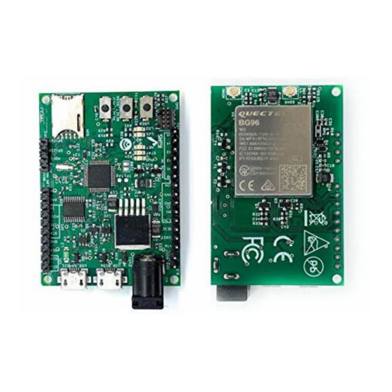
2.2 Key Features Atmel ATSAMD21G18 MCU • • Quectel BG96 NB-IoT module External GPS antenna Connector • • External LTE antenna connector Supports LTE NB-IoT and Machine Type Communications (MTC) • • Supports EGPRS • Global Frequency Band B1/B2/B3/B4/B5/B8/B12/B13/B18/B19/B20/B26/B28/B39 (B39 for Cat.M1 only) for LTE and 850/900/1800/1900MHz for EGPRS... - Page 7 Figure 2. Hardware Board Overview Diagram – Top and Bottom View Board Rev 2.2 Copyright © 5GHUB.US...
-
Page 8: Physical Characteristics
Thickness 1.6mm BG96 USB MCU USB AREF IOREF RESET MISO 3.3V MOSI ADC0 ADC1 STAT GPIO26 GPIO64 42mm Figure 3. Top and Bottom Views 2.4 Physical Characteristics The width and length of the board is 48mm (width) by 52 mm (length). The board have four screw holes in each corner that allows the board to be attached to a surface or case. - Page 9 Figure 4. Hardware Board Top View – External Dimensions Board Rev 2.2 Copyright © 5GHUB.US...
-
Page 10: Peripherals - Key Components
2.5 Peripherals – Key Components DC INPUT POWER SUPPLY BG96 USB Port USB_BOOT JUMPER MCU USB Port J105 HEADER J101 HEADER J106 HEADER PWR LED JP2 HEADER STAT LED Nano SIM Card Slot NET LED MCU RESET LD1 LED BG96 RESET... -
Page 11: Peripherals - Io Connections
ADC1 GPIO26 GPIO64 Power GPIO BG96 PINs UART Figure 7. Board Extension Connectors * I2C interface lines might be configured as USART interface SDA line can work then as USART TXD and SCL line can work as USART RXD) ** MOSI and SCK lines might be configured as USART interface (MOSI line can work then as USART TXD and SCK line can work as USART RXD) Board Rev 2.2... -
Page 12: Hardware Specification
Interfacing Logic Voltage Level (Operating 3.3V Voltage) Voltage output 5V, 3.3V RESET buttons Two; one for MCU and one for BG96 User-defined Button 1 connected to MCU 14 (A0-A5, PA6, PA7, SS, MOSI, MISO, SCK, SDA, General-purpose digital I/O Pins SCL) -
Page 13: Pin Description
LED2 (USER) HIGH value, the LED is on, when the pin is LOW, it is off LED (NET) Indicate the BG96 operation status LED (STAT) Indicate the BG96 network activity status MCU RESET Reset the MCU button BG96 RESET Reset the BG96 module... -
Page 14: Bg96 Chipset
Applying voltages higher than 3.3V to any I/O pin could damage the board 2.9 BG96 chipset All functionality of the BG96 shipset shall be implemented excluding the following features. That is, the following features are not supported [1][2]. Audio, Earphone, and Codes are not supported. -
Page 15: Using The Board With Arduino Ide
1- Connect a USB cable from the computer USB to the USB_SAMD21 port to power on the board. 2- Connect a USB cable from the computer USB to the USB_BG96 port to connect to the BG96. 3- Launch Arduino IDE and choose File->Preferences. In the Additional Boards Manager URLs, insert the following URL: https://raw.githubusercontent.com/5ghub/5G-NB-IoT/master/package_5G-NB-IoT_index.json... - Page 16 5- Choose “5G NB-IoT (Native USB Port)” 6- In the Arduino IDE, Choose Port and select the serial port where the board appears. Board Rev 2.2 Copyright © 5GHUB.US...
- Page 17 7- In the Arduino IDE, Choose Sketch->Include Library->Add .Zip Library and select the file 5G-NB-IoT_Arduino.zip You are now ready to start running Arduino sketches and projects. Board Rev 2.2 Copyright © 5GHUB.US...
-
Page 18: Running Arduino Sketch
2- In the Device manager, the Arduino and Quectel USB Modem and ports shall show up as in this screen shoot: After compiling and uploading the Arduino sketch, the LEDs will blink and the BG96 is enabled as in the following picture: Board Rev 2.2... - Page 19 The following table show different five LEDs status after uploading this sketch Behavior Description Indicates the MCU is powered on STATE Indicates the BG96 is powered on Flicker slowly (200ms High/1800ms Low) Network Searching Flicker slowly (1800ms High/200ms Low) Idle...
-
Page 20: Using The Arduino Sketches With Serial Interface
4 Using the Arduino Sketches with Serial Interface The board has a serial interface where output can be sent via the serial interface to the computer. Use USB-to-Serial cable such as the Prolific USB-to-Serial cable. Connect the USB-to-Serial cable to the PC, and the device manager shall display a new COM port. Board Rev 2.2 Copyright ©... - Page 21 The board has the serial interface on the J101 as in the following figure. PA7 (TX) (GREEN) PA6 (RX) (WHITE) Connect the USB-to-Serial cable from the PC to the board as shown. Launch any serial port software to connect to the board serial board. Set the COM speed to 115200. Board Rev 2.2 Copyright ©...
- Page 22 Click connect and the Arduino sketch output shall be displayed on the terminal software Board Rev 2.2 Copyright © 5GHUB.US...
-
Page 23: Procedure For Operating The Bg96 Wireless Unit
5 Procedure for Operating the BG96 Wireless Unit 1. Insert a USIM (or a test USIM) into the USIM slot on the hardware board. 2. Connect the LTE/GPS Antenna to the MAIN and GNSS antenna ports respectively on the board. - Page 24 5. Launch QNavigator. Choose the correct Quectel USB AT port in Settings->Serial Port Parameter Set. Board Rev 2.2 Copyright © 5GHUB.US...
- Page 25 6. Click “Connect”. The board will connect to Mobile operator. Screen shot below shows it connects to T-Mobile network. Board Rev 2.2 Copyright © 5GHUB.US...
- Page 26 7. On the Windows PC, disable all network connections (WiFi or Ethernet) except the Quectel cellular Modem. You can, for example, do a “Ping” to any IP address and this illustrates transmitting and receiving from the T-Mobile cellular network. This is illustrated as in this screen shot: Board Rev 2.2 Copyright ©...
-
Page 27: Running The Gnss
6 Running the GNSS You can use the GNSS module to get location and position information: 1. Connect the second Antenna to the GNSS antenna port on the board. In the QNavaigator, click “GNSS” and then “Connect”. You will get location and positioning information. Sample screen shots as below: Board Rev 2.2 Copyright ©... - Page 28 Board Rev 2.2 Copyright © 5GHUB.US...
-
Page 29: At Commands
7 AT Commands The QNavigator can be used to communicated with the transmitter and receiver. For example, you can use the following AT commands: a. ATI: The ATI command displays the module information, such as the name and version b. AT+CFUN?: This commands sets up phone functionality in the module. In our case it is 1, because we require full functionality. - Page 30 AT+QGPSCFG="outport","usbnmea": Use this command to configure various GNSS settings, including NMEA sentences output to the BG96 USB port. The BG96 is connected to two GPIOs (GPIO26 and GPIO64) which produces a maximum of 1.8V. You can set them using the following commands: AT+QCFG="gpio",1,26,1,0,7 //configure pin 26 as output, no pull, 17mA drive, clean last configuration AT+QCFG="gpio",3,26,1...
- Page 31 2. You can send SMS from the SMS pane of the QNavigator. Screenshots below shows the SMS transmitted by the device and received on the phone. Board Rev 2.2 Copyright © 5GHUB.US...
-
Page 32: References
8 References [1] Quectel_BG96_Hardware_Design_V1.2.pdf [2] Quectel_BG96_Reference_Design_Rev.A_20170814.pdf [3] Quectel_Antenna_Design_Note_V2.0.pdf [4] Quectel_RF_Layout_Application_Note_V2.2.pdf [5] Quectel_QFlash_User_Guide_V2.3 [6] Arduino IDE, https://www.arduino.cc/en/Main/Software [7] Arduino IDE, https://www.arduino.cc/en/Guide/ArduinoZero [8] Microchip, “Low-Power, 32-bit Cortex-M0+ MCU with Advanced Analog and PWM” Board Rev 2.2 Copyright © 5GHUB.US... -
Page 33: Appendix A - Schematic
APPENDIX A – SCHEMATIC Board Rev 2.2 Copyright © 5GHUB.US...