Hussmann GSVM Instructions Manual
Hussmann gsvm merchandisers: installation instruction
Hide thumbs
Also See for GSVM:
- Installation & operation manual (48 pages) ,
- Installation & service manual (44 pages)

Related Manuals for Hussmann GSVM


Summary of Contents for Hussmann GSVM
- Page 1 Operating and Installation MODEL: GSVM – Self Contained Medium Temperature Cases for Dairy, Beverages, and Deli Products Instructions OII - GSVM January 2005...
-
Page 2: Table Of Contents
Introduction Inspection Location and Clearance Skid Leveling Sealing Access Panel Removal Legs Serial Plate Air distribution and Product Loading Power Requirements Electrical Box Power Switch Defrost Time Clock Connections Drains Dimensions Electrical BTU Capacity Shelving Maximum Weight Capacities Temperature Control Condensing Unit Shelves Thermometer... - Page 3 Warranty and Parts Information Wiring Diagrams This GSVM case was manufactured in Gloversville, New York. Our phone #’s are (518) 725-0644 for New York State residents and our toll free #800-753-7790 for outside New York – should you have further questions.
-
Page 4: Introduction
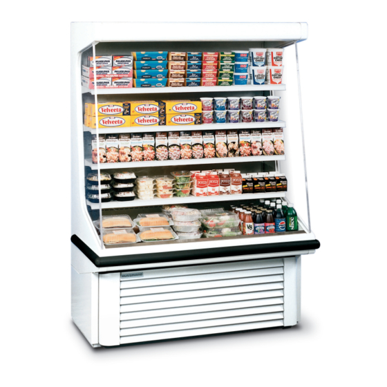
INTRODUCTION – The Hussmann Model GSVM open vertical merchandiser offers versatility in the display of medium temperature (35- 41ºF) products such as diary products, prepared salads, pizza and fresh entrees that are pre-chilled in a cooler. So that you can realize maximum... -
Page 5: Leveling
The procedure is repeated on the op- posite end. When the leg levelers are in place, the case may be slid off the skid and placed in its final location. LEVELING – The cabinet must be leveled properly to insure full drainage of condens ate water from the evaporator coil. -
Page 6: Air Distribution And Product Loading
Do not load product so that it extends over the shelf edges or over the return air grille. POWER REQUIREMENTS – The GSVM Models are equipped for operation on a 115/60/1 power supply. See chart in specifications for requirements. It is very important for the safety of both you and your customer to have each circuit properly grounded. -
Page 7: Connections
each. There are 4 defrost on the 5272 (2 a.m., 8 a.m., 2 p.m., and 8 p.m.) at 30 minutes each Additional defrost may be re- quired for cases located in high humidity or high us age cases. If possible, avoid setting a defrost during the day, or peak usage periods. -
Page 8: Dimensions
GSVM4072 115/60/1 GSVM5272 115/60/1 GSVM5272 115/60/1 ** The GSVM-5272 changed to R404A in January 2000. Check the Serial Plate to verify the correct refrigerant. Note: Applies to the GSVM4072 & 5272 Models Only-Drain Plumbing hookup recommended. Optional condensate is available if there is no access to drain plumbing. -
Page 9: Temperature Control
Bottom Sheet Metal Area Stand. 13”/15” shelves Stand. 13”/15” shelves w/optional upslope 6º adapters Optional Wire Baskets OPERATION and MAINTENANCE - It is important that the two previous sections of this installation booklet have been read and followed carefully before attempting to start up the equipment. -
Page 10: Condensing Unit
correspond to the actual cabinet tempera- ture due to the bulb location and depend- ing on various conditions, a certain amount of time lag will be noticed between the new setting and the resulting temperature. CONDENSING UNIT – A regular program should be set up for cleaning the fin-and -tube condenser. -
Page 11: Lighting
Do not use an abrasive cleanser on the painted surfaces GSVM-4060 only has Electric Condensate Pan as Standard Wipe dry before restarting the cabi- net. The time clock (see Defrost Time Clock section) should be reset to the correct time of day. -
Page 12: Refrigeration
Comet, Bab-O, Liquid NuSteel, Cooper’s Stainless Steel Cleaner, and Al- len’s Stainless Steel Cleaner. REFRIGERATION – The GSVM models employ a refrig- eration system using a hermetic compres - sor. The GSVM4060 and GSVM4072 sys - tems employ a capillary tube for refriger- ant flow control. -
Page 13: Temperature Control
Be sure that all s ervice valves are open to al- low all of the mixture to be discharged. b. Connect a deep-drain vacuum pump to both the high and l ow side of the system. Pull a vacuum on the system to at least 1500 microns. -
Page 14: Trouble Shooting Charts
TROUBLE Compressor will not start no noise Compressor will not start, cuts out on overload Warm storage temperature 1. Temperature control not TROUBLE SHOOTING CHARTS PROBABLE CAUSE 1. Power disconnected 2. Blown fuse or breaker 3. Defective or broken wiring 4. - Page 15 Compressor runs continuously. Product too warm Compressor runs continuously. Product too cold TROUBLE SHOOTING LIGHT CHART PROBLEM Lights won’t start Lights flicker 4. Refrigerant overcharge 5. Low voltage, compressor cycling on overload 1. Short of refrigerant 2. Inefficient compressor 1. Defective control 2.
-
Page 16: Gsvm Accessories
Ballast Hums The following is a description of the various accessories available for the GSVM, including sketches, where applicable of the many shelving/wire goods items available. CASTER KIT – Consists of 5" braking casters, which screw in to the standard threaded holes in the four corners under the case occupied by the standard leg levelers, which will have to be removed. -
Page 17: Warranty And Parts Information
IMPORTANT – Please read carefully to assure prompt and accurate service. ORDERING PARTS REPLACEMENT – Contact your nearest Hussmann Distributor. Always specify model and serial number of cabinet. If correct part number is not know, give a clear description of part itself and its function in the cabinet or... -
Page 18: Wiring Diagrams
Lack of any of the above information may result in the shipment of the wrong part, or a delay in shipment. COMPRESSOR REPLACEMENT PROCEDURE – Replacement compressors will not be shipped from the Hussmann factory. They may be obtained from you nearest Copeland Wholesaler. - Page 19 POWER CORD REV. DATE WIRE HARNESS EVAP. FANS COMPRESSOR PROTECTOR #1 RELAY TEMP. CONTROL TIME CLOCK CONDENSATE PAN POWER SWITCH GSVM 4060 SHEET TOLERANCES UNLESS MATERIAL: OTHERWISE S PECIFIED. SIZE FRACTIONAL 1/32" XXXXXX-XX Gloversville, N.Y. 12078 DECIMAL 0.031" WIRING DIAGRAM...
- Page 20 1 Ph 11/7/95 REV. DATE EVAP. FANS COMPRESSOR PROTECTOR #1 RELAY TEMP. CONTROL TIME CLOCK OPTIONAL CONDENSATE PAN POWER SWITCH (1,000W,9A,120V) GSVM 4072 SHEET TOLERANCES UNLESS MATERIAL: OTHERWISE SPECIFIED. SIZE FRACTIONAL 1/32" XXXXXX-XX DECIMAL TITLE WIRING DIAGRAM ANGULAR SIZE HOLE LOCATION XXXXXXXXXX &...
- Page 21 OPTIONAL SHELF LIGHT LAMP BALLAS T LIGHT SWITCH STD. SHELF LIGHT LAMP BALLAS T LIGHT SWITCH STD. SHELF LIGHT LAMP BALLAS T LIGHT SWITCH STD. SHELF LIGHT LAMP BALLAS T LIGHT SWITCH UPPER LIGHT LAMP LIGHT SWITCH STARTER 115 V 60 Hz 1 Ph USE COPPER CONDUCTORS ONLY...
- Page 22 115 V 60 Hz 1 Ph 11/7/95 REV. DATE EVAP. FANS COMPRESSOR TEMP. CONTROL TIME CLOCK OPTIONAL CONDENSATE PAN POWER SWITCH (1,000W,9A,120V) GSVM 52072 (R-404A) SHEET TOLERANCES UNLESS MATERIAL: OTHERWISE SPECIFIED. SIZE FRACTIONAL 1/32" XXXXXX-XX DECIMAL TITLE WIRING DIAGRAM ANGULAR SIZE...