Pioneer X-HM81-K Service Manual
Network cd receiver system
Hide thumbs
Also See for X-HM81-K:
- Operating instructions manual (42 pages) ,
- Quick start manual (33 pages)
Table of Contents
Advertisement
Quick Links
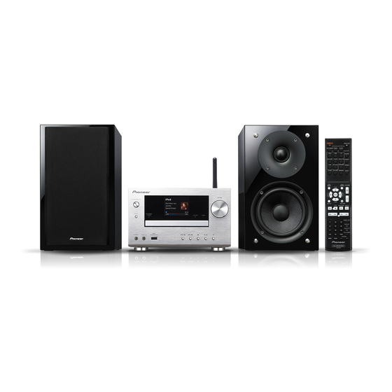
NETWORK CD RECEIVER SYSTEM
X-HM81-K
X-HM81-S
X-HM71-K X-HM71-S
NETWORK CD RECEIVER
XC-HM81-K XC-HM81-S
THIS MANUAL IS APPLICABLE TO THE FOLLOWING MODEL(S) AND TYPE(S).
Model
X-HM81-K, X-HM81-S
XC-HM81-K, XC-HM81-S
X-HM71-K, X-HM71-S
X-HM71-K
X-HM71-S
PIONEER CORPORATION
PIONEER ELECTRONICS (USA) INC. P.O. Box 1760, Long Beach, CA 90801-1760, U.S.A.
PIONEER EUROPE NV Haven 1087, Keetberglaan 1, 9120 Melsele, Belgium
PIONEER ELECTRONICS ASIACENTRE PTE. LTD. 253 Alexandra Road, #04-01, Singapore 159936
PIONEER CORPORATION 2012
Type
Power Requirement
SYXE8
AC 220 V to 240 V
SYXE8
AC 220 V to 240 V
SYXE8
AC 220 V to 240 V
CXE
AC 120 V
AXQ5
AC 220 V
1-1, Shin-ogura, Saiwai-ku, Kawasaki-shi, Kanagawa 212-0031, Japan
X-HM81-K
K-MZV AUG.
ORDER NO.
RRV4322
Remarks
2012 Printed in Japan
Advertisement
Table of Contents

Related Manuals for Pioneer X-HM81-K


Summary of Contents for Pioneer X-HM81-K
- Page 1 PIONEER CORPORATION 1-1, Shin-ogura, Saiwai-ku, Kawasaki-shi, Kanagawa 212-0031, Japan PIONEER ELECTRONICS (USA) INC. P.O. Box 1760, Long Beach, CA 90801-1760, U.S.A. PIONEER EUROPE NV Haven 1087, Keetberglaan 1, 9120 Melsele, Belgium PIONEER ELECTRONICS ASIACENTRE PTE. LTD. 253 Alexandra Road, #04-01, Singapore 159936 PIONEER CORPORATION 2012 K-MZV AUG.
-
Page 2: Safety Information
Health & Safety Code Section 25249.6 - Proposition 65 Laser Pickup specifications and Laser characteristics For CD Wave length (typ) : 790 nm Operation output : 3 mW CW, Class 1 Maximum output : Class 1 (Under fault condition) LABEL CHECK SYXE8 model AXQ5 model CXE model X-HM81-K... -
Page 3: Table Of Contents
11.2 TUNER and BT ASSYS.............................. 90 11.3 MAIN ASSY ................................92 11.4 BCO ASSY ................................. 96 11.5 CNT1, CNT2 and CNT3 ASSYS..........................98 11.6 F_AUX, F_USB, FRONT, KEY and DOCKING ASSYS .................... 102 11.7 POWER ASSY................................106 12. PCB PARTS LIST ................................108 X-HM81-K... -
Page 4: Service Precautions
Replace the MAC address seal with a new one, which you can find enclosed with the service part. MAC Address seal Attach the Mac Address label to the rear panel, above the WLAN antenna, so that it will not block the ventilation holes on the rear panel. X-HM81-K... -
Page 5: Specifications
• Non skid pad x 8 (X-HM81 only) • AM loop antenna (8952SHM810018-IL) (E601019000010-IL) • Warranty card • FM wire antenna (E605010140010-IL) • Quick Start Guide (SYXE8 model: 5707000006940-IL) • WLAN antenna (CXE model: 5707000006970-IL) (E600223170010-IL) (AXQ5 model: 5707000006980-IL) • Operating instructions (CD-ROM) (6517000000821-IL) X-HM81-K... -
Page 6: Basic Items For Service
Diagnosis (CNT2 Assy ↔ CNT3 Assy) BtoB extension jig cable GGD1810 Diagnosis (MAIN Assy ↔ CNT1 Assy) BtoB extension jig cable GGD1811 Diagnosis (MAIN Assy ↔ CD Assy) BtoB extension jig cable GGD1812 Diagnosis (FRONT Assy ↔ CNT3 Assy) FPC Extension jig GGD1813 X-HM81-K... -
Page 7: Pcb Locations
3.3 PCB LOCATIONS BCO_STOPPER ASSY BT ASSY (X-HM81 only) MAIN ASSY BCO ASSY TUNER ASSY CNT2 ASSY CNT3 ASSY CD ASSY CNT1 ASSY POWER ASSY MECHA F_USB ASSY KEY ASSY DOCKING ASSY F_AUX ASSY FRONT ASSY Cabinet (Bottom view) X-HM81-K... - Page 8 Parts marked by “NSP” are generally unavailable because they are not in our Master Spare Parts List. The > mark found on some component parts indicates the importance of the safety factor of the part. Therefore, when replacing, be sure to use parts of identical designation. LIST OF ASSEMBLIES X-HM81-K X-HM81-S XC-HM81-K XC-HM81-S...
- Page 9 X-HM81-K...
-
Page 10: Block Diagram
31: CPU_GND 7: A_GND 8: CD_L 9: A_GND CP602 10: CD_R 11: M_GND F_AUX ASSY 12: M_GND 13: CD_RX 14: CD_TX (7028072535010-IL) 15: CD_RST 16: MAIN_BUSY 17: NC PN1702 CN515 FPC515 CP500 FRONT ASSY MOD500 (7028072531010-IL) CP508 F_USB ASSY (7028072536010-IL) X-HM81-K... - Page 11 (7028072301010-IL) 12: M_GND 9: NC 13: CD_RX 10: A_+12V 14: CD_TX 11: A_+12V 15: CD_RST 12: A_GND 16: MAIN_BUSY 13: A_GND PN1604 PN1603 17: NC 14: A_-12V 15: A_-12V PN1702 PN1705 KEY ASSY (7028072533010-IL) -IL) MECHA CN502 (8030000010080-IL) CP508 X-HM81-K...
-
Page 12: Overall Block Diagram
MAIN ASSY Note: Be blocks in MAIN ASSY other than blocks. (There are some exceptions) IC603 NJU7391 IC704 INPUT SELECT & VOLUME IC208 CNT2 ASSY IC12, 18, 19 CR870 SDRAM NAND_Flash BCO ASSY IC609 SYSTEM U M3030 FRONT ASSY X-HM81-K... - Page 13 LC_FILTER Speaker AMP BLOCK IC608, 612 Q610,615,619,621 MOSFET IRF6645 IRS2092S Headphone IC605 IC606 Subwoofer TUNER ASSY IC400 -6dB DOCKING_VIDEO +6dB CVBS CD BLOCK CD ASSY IC609 SYSTEM U-com M30302 RMC500 X-HM81-K...
-
Page 14: Power Supply Block Diagram
4.3 POWER SUPPLY BLOCK DIAGRAM B+_27V S1(AMP +B) B-_27V IC301 S2(+12V,-12V) IC303 BCO_+12V S3(USB/CD) MOT_+8V IC311 AC CORD IC315 MICOM_ SUB TRANS X-HM81-K... - Page 15 B+_27V +33V(NO LOAD) AMP_+5V -33V(NO LOAD) B-_27V AMP_-5V A_+12V IC301 IC305 IC701 IC307 A_-12V IC303 IC11 IC13 BCO_+12V IC14 MOT_+8V IC313 C311 CD_+3.3V MAIN TRANS SPEC(-) NO_LOAD RATED_VOLTAGE CURRENT 21.5V 2.2A 20.2V 0.46A 13.6V 4.2A 17.4V 8.7V IC315 MICOM_3V9 X-HM81-K...
-
Page 16: Diagnosis
• Detection an overcurrent of power of Front USB or iPod Dock. Does USB protect Check the IC11 and IC14 and its peripheral circuits. work? Check the short-circuit of 5V power of Front USB or iPod Dock (BCO Assy/DOCKING Assy/F_USB Assy). Be not the trouble that each Protect circuit works. X-HM81-K... - Page 17 Assy) and IC208. • Replace the CR870 (MODULE on BCO Assy). (CNT2 Assy) Output it depending on input • Check the input blocks and its peripheral circuits and power supply voltages. • Replace the CR870 (MODULE on BCO Assy). X-HM81-K...
- Page 18 (CD Assy) Does signals output from CD UCOM (IC1604) • Check the IC1604 and its peripheral circuits. (CD Assy) pin 25, 27, 28 (MAIN_BUSY, CD_RX, CD_TX)? (CD Assy) • Check the IC1601, IC1606 and its peripheral circuits. (CD Assy) X-HM81-K...
- Page 19 • Check the connection between the F_USB Assy and BCO Assy. Is there USB • Check the IC12 and its peripheral circuits. (BCO Assy) signal at 3 and 4 Pins of • Replace the CR870 (MODULE on BCO Assy). CP500? • Replace the CR870 (MODULE on BCO Assy). X-HM81-K...
- Page 20 CVBS signal output to • Check the connection between the DOCKING Assy and connector (CP4) TUNER Assy. pin 2? (DOCKING Assy) • Check the internal circuits of the DOCKING Assy. • Check the setting of iPod/iPhone that is external connection. X-HM81-K...
-
Page 21: Protection Circuit
B+ (+33 V). The protection circuit is activated when the signal at Pin 3 of IC601 changes from H to L. MAIN ASSY M3V3_SW MAIN_MICOM DC_PROTECT IC601_3 pin DC_PROTECT D620 KDS4148U C731 R824 100N-K 100K R826 47K(1/4) MTZ22B Q636 KTC3198 R827 X-HM81-K... - Page 22 The protection circuit is activated when abnormally high temperature is detected by the P600 PTC thermistor near IC608 (AMP_Lch). The circuit is activated when the signal at Pin 92 of IC601 changes from H to L. MAIN ASSY M3V3_SW MAIN_MICOM IC601_92 pin OVER_ OTP1 TEMPERATURE_ PROTECT_1 X-HM81-K...
- Page 23 Front USB or iPod Dock. The circuit is activated when the signal at Pin 70 of IC1 changes from H to L. BCO ASSY BCO MODULE (CR870) D3.3V DM870 F_USB SW FAULT M2 VCO0 IC11_8 pin DOCKING SW IC14_8 pin X-HM81-K...
-
Page 24: Power Management
STANDBY/ON on the remote control unit Power On -> iPodCharge Sleep AutoPowerOff Removal/insert of the dock Returning to Network Standby Note: The power-off status caused by activation of a protection circuit is not described in this section. See "5.2 Protection circuit." X-HM81-K... -
Page 25: Checking Terminals
4 Double-click on Internet Protocol. IP address: 192.168.0.1 Subnet mask:255.255.255.0 Gateway address: 0.0.0.0 DNS (1st): 0.0.0.0 DNS (2nd): 0.0.0.0 Proxy setting: Not to be used 5 After setting is finished, reboot the unit. MAC Address seal 5 Set the items as shown below. X-HM81-K... - Page 26 If the SSID for the prepared router is displayed on the list, the Wi-Fi antenna works properly. Note: As the SSID name for a wireless LAN router supports only one-byte alphanumerics, if two-byte characters are used in an SSID name, rename it. X-HM81-K...
- Page 27 Reconnect the Apple device to the Dock. If the CHARGE LED lights and charging starts, it is OK. If charging does not start, refer to the diagnosis flowchart for a case in which the Docking Terminal cannot be recognized on "5.1 TROUBLESHOOTING".. X-HM81-K...
-
Page 28: Ic Information
Data output of network module communication (Sub->DM860) P11/EX25/SI00/RxD0 RX0_DO_NW Data input of network module communication (DM860->Sub) P10/EX24/SCK00 CLK_NW Clock output of network module communication AVREF1 AVREF1 P110/ANO0 BT_MUTE BT MUTE Active: L P111/ANO1 CS_NW Chip select output of network module communication AVREF0 AVREF0 X-HM81-K... - Page 29 Ground (except P121-P124 and port block) EVSS0 EVSS0 Ground of port block (except P20-P27, P110, P111, P121-P124, P150-P157) Positive power supply (except P121-P124 and port block) EVDD0 EVDD0 Positive power supply of port block (except P20-P27, P110, P111, P121-P124, P150-P157) X-HM81-K...
- Page 30 LOW VOLTAGE VIDEO AMPLIFIER WITH LPF • Pin Arrangement • Block Diagram • Control Terminal J126012010010-IL (PQ012FZ01ZP)(BCO ASSY: IC2) Voltage Regurator • Pin Arrangement • Block Diagram DC input (Vin) DC output (Vo) Specific IC Bias power supply (VB) ON/OFF control (VC) X-HM81-K...
-
Page 31: Service Mode
O t h e r . : 1 . 0 0 0 / 1 . 0 0 / 1 . 0 0 M16C / uPD78F0515 / S5L8035 M o d e l : X C - H M 7 1 Model name recognized by the software XC-HM71 / XC-HM81 X-HM81-K... - Page 32 (it may take up to dozens of seconds), then the Protect Check Mode screen will be displayed. Example: Startup → Pioneer Logo → Music Server screen → Network established → Protection Check screen Canceling Operation Lock...
-
Page 33: Protect Check Mode
"g (STOP)" and "STANDBY/ON" buttons Unit "STANDBY/ON" during Cold Standby. The last protection activation that was detected before Protect Check mode is entered will be displayed. Unit "np" Unit "np" Unit "np" Unit "np" Unit "np" X-HM81-K... - Page 34 Unit "STANDBY/ON" To turn the unit off, press the "STANDBY/ON" butonn during Protect Check mode. Remarks During Protect Check mode, response to keys other than those described below is disabled. Unit "np" button Unit "f (Play/Pause)" button Unit "STANDBY/ON" button X-HM81-K...
-
Page 35: Checking The Lcd
Each time the 1 key on the remote control unit supplied with the product is pressed, the screen is changed as shown below Ramp > Black > White > Red > green > Blue If the 0 key is pressed, the screen will return to that of playback. [Screens to be displayed] X-HM81-K... -
Page 36: Rds Characters
This unit can display all the characters that are indicated in the white cells in the table below properly but cannot display the characters in gray cells properly and will indicate such characters as "#." Those are the characters shown below in the RDS standard: 0x5E 0x60 0x7E X-HM81-K... -
Page 37: Disassembly
• FPC Extension jig (GGD1813) [1] Cabinet and DOCKING Assy • Cabinet Cabinet Cabinet (1) Remove the eight screws. (K: B020030083F10-IL) (S: BBZ30P080FNI) • Rear view (2) Remove the cabinet. Note: Please do not damage the cables when removing Cabinet the cabinet. X-HM81-K... - Page 38 (B020030084F10-IL) (3) Unhook the two hooks. • Bottom view (4) Disconnect the one flexible cable and one connector. CNT3 Assy (FPC2, CP607) (5) Remove the two screws. CP607 (B020030084F10-IL) (6) Remove the front panel section. FPC2 Front panel section X-HM81-K...
- Page 39 (1) Remove the one cushion. Back chassis (2) Remove the 13 screws. (BBT30P100FTB) (for X-HM81 and XC-81M) (2) Remove the 11 screws. (BBT30P100FTB) (for X-71HM) (3) Remove the back chassis. • Rear view X-81HM, XC-81HM only X-81HM, XC-81HM only X-HM81-K...
- Page 40 (PN1701, 1702) (4) Remove the CD Assy. PN1702 PN1701 (5) Short-circuit position of figure solodering. CD Assy (short) Note: After working, connect the flexible cable, then remove the soldered joint (open). (6) Disconnect the one flexible cable. (PN1602) PN1602 MECHA X-HM81-K...
- Page 41 (4) Remove the CNT3 and CD Assemblies. (See procedure [4].) • MAIN Assy (1) Remove the one screw. (B020230083B10-IL) Front side • Bottom view (2) Disconnect the one BtoB connector. MAIN Assy (CP605) (3) Remove the MAIN Assy. CP605 CNT1 Assy X-HM81-K...
- Page 42 (See procedure [4].) (3) Remove the back chassis. CNT2 Assy (See procedure [3].) • TUNER, CNT2 and BCO Assy CP400 (1) Release the two jumper wires. (2) Remove the TUNER Assy by disconnecting the one BtoB connector. TUNER Assy (CP400) X-HM81-K...
- Page 43 Extension jig cable Insulation sheet PN1702 PN1705 (GGD1812) CP604 CNT3 Assy CP310 CP31 Cut it CP30 CP512 BCO Assy POWER Assy CNT2 Assy CP506 Make sure to match color of cord. CN511 CP505 Extension jig cable (GGD1810) Extension jig cable (GGD1773) X-HM81-K...
- Page 44 If the POWER Assy is not assembled as described above, it will be attached nearer to the front than as designed, with the result that the cabinet and the rear panel may be separated by a gap or that the front panel may be inclined forward. X-HM81-K...
-
Page 45: Each Setting And Adjustment
2. Plug the Power cord. (STANDBY mode) For updating of the MAIN microcomputer, proceed with Please push the cancel button and press the JIG's the following steps in STANDBY mode. RESET button. And confirm a connection of FFC. Please return to procedure 1. X-HM81-K... - Page 46 1 Set speed of update. 1 Set speed of update. Set Baud rate to 38400. (Default Baud rate is 9600) Press the OK button. 2 Update the MCU. E.P.R=>Erase+Program+Read 2 Update the MCU Press the E.P.R … button Press OK button. X-HM81-K...
- Page 47 [RETURN] File Not Found memory. Select ENTER, return to Service Menu, then retry using the USB memory in which the updater file is stored. * The same message will be displayed [ENTER] if no USB memory is plugged in. X-HM81-K...
- Page 48 Key operation Approx. 20 sec. the background will be displayed. disabled After restart is completed, the Key operation updating process will automatically disabled start. The progress of updating will be displayed with the progress bar. In units of 20% X-HM81-K...
- Page 49 This screen remains displayed if updating fails. For recovery, unplug the power cord then plug it back in. The unit will start with the previous version of the program. Updating may fail if the updater file has erroneous data. X-HM81-K...
- Page 50 3. Set the Function selection to CD. 4. Open the disc tray, load the created disc, then close the tray. 5. Updating starts automatically. 6. After updating is completed, the disc tray will be automatically opened. 7. Unload the disc then turn the unit OFF. X-HM81-K...
-
Page 51: Initial Settings
8.2 INITIAL SETTINGS X-HM81-K... -
Page 52: Exploded Views And Parts List
S-HM71 (for X-HM71) S-HM81SA (for X-HM71-S/AXQ5) Speaker AAA size IEC R03 S-HM81GB, S-HM81SA dry cell batteries (for X-HM81) Speaker S-HM71 (for X-HM71) Front Polybag packing style Tape Polybag packing style (10 x 100) Front Tape (clear) (clear) (side) Bottom Power cord X-HM81-K... - Page 53 21 Snow Cushion See Contrast table (2) 22 Bag Poly See Contrast table (2) (2) CONTRAST TABLE X-HM81-K/SYXE8, X-HM81-S/SYXE8, XC-HM81-K/SYXE8, XC-HM81-S/SYXE8, X-HM71-K/SYXE8, X-HM71-K/CXE, X-HM71-S/SYXE8 and X-HM71-S/AXQ5 are constructed the same except for the following: Mark No. Symbol and Description X-HM81-K/SYXE8...
-
Page 54: Exterior Section
9.2 EXTERIOR SECTION Bracket-mecha guide Bracket-mecha guide Shield plate-iPod Cushio LCD Shield plate-AUX Cushio LCD Shield plate-USB Bottom chass X-HM81, XC-HM81 only X-HM81-K... - Page 55 * When you take a cushion, change it for a new one. Except AXQ5 model BRIDGE-CO Module X-HM81, XC-HM81 only X-HM81, guide XC-HM81 only Bracket side Support Bracket side Main chassis Support Support Support Bottom chassis X-HM81, XC-HM81 only X-HM81, XC-HM81 only X-HM81-K...
- Page 56 See Contrast table (2) 38 Cushion FLT (BCO2) 4050214045000-IL 39 Cover Tray CD See Contrast table (2) 40 Cover iPod See Contrast table (2) 41 Holder See Contrast table (2) 42 Guide 4350210471000-IL 43 Stopper 4380040162010-IL 44 Plate 4470212226000-IL 45 Window 5077213343000-IL X-HM81-K...
- Page 57 (2) CONTRAST TABLE X-HM81-K/SYXE8, X-HM81-S/SYXE8, XC-HM81-K/SYXE8, XC-HM81-S/SYXE8, X-HM71-K/SYXE8, X-HM71-K/CXE, X-HM71-S/SYXE8 and X-HM71-S/AXQ5 are constructed the same except for the following: Mark No. Symbol and Description X-HM81-K/SYXE8 X-HM81-S/SYXE8 XC-HM81-K/SYXE8 XC-HM81-S/SYXE8 TUNER Assy 7028072534030-IL 7028072534030-IL 7028072534030-IL 7028072534030-IL BT Assy 7028072537010-IL 7028072537010-IL 7028072537010-IL...
-
Page 58: Speaker Section (S-Hm81Gb, S-Hm81Sa)
Wood cabinet Assy Label Main Holder catch SYXE8 SYXE8 only only Holder catch Holder catch Holder catch Badge Pioneer (1) SPEAKER SECTION (for X-HM81) SECTION PARTS LIST Mark No. Description Part No. Mark No. Description Part No. 11 Felt (TW) 8952SHM710015-IL... -
Page 59: Spaeker Section (S-Hm71)
9.4 SPAEKER SECTION (S-HM71) S-HM71 (for X-HM71) Label Main Wood cabinet Assy Holder catch Holder catch Holder catch Holder catch Badge Pioneer SPAEKER SECTION (for X-HM71) SECTION PARTS LIST Mark No. Description Part No. 1 Unit Woofer 8952SHM710014-IL 2 Tweeter... -
Page 60: Schematic Diagram
10. SCHEMATIC DIAGRAM 10.1 CD ASSY PN1607 2.5mm * 2Pin (CD) (CD) X-HM81-K... - Page 61 CD ASSY (7028072301010) (CD) : Audio Signal Route (CD Lch) (CD) PN1607 2.5mm * 2Pin (CD) (CD) 2.5mm * 6Pin X-HM81-K...
-
Page 62: Tuner And Bt Assys
(LINE) 330P-J (SW) (SW) C408 330P-J R413 R414 (SW) (SW) JK402 (LINE) R418 R417 (LINE) Q401 Q400 KTC2875B KTC2875B C412 100P-J (TU) (TU) (TU) TUNER_PACK_OPTION KST-MW104MV1-S78A RDS NON (TU) KST-MW004MV1-S78A TUNER_OPTION VCC_GND AUD_R AUD_L AGND DAB_RX//M_TX DAB_TX//M_RX RESET SPDIF X-HM81-K... - Page 63 : Audio Signal Route (SubWoofer ch) (LINE) : Audio Signal Route (LINE IN L ch) (TU) : Audio Signal Route (TUNER L ch) (SW) (SW) (LINE) (LINE) CP402 (TU) (TU) X-HM81, XC-HM81 ONLY BT ASSY (7028072537010-IL) R1017 R1018 Q1002 Q1003 KTC2875B KTC2875B X-HM81-K...
-
Page 64: Main Assy (1/3)
(SW) D601 KTA1504S R679 R681 Q603 KRC102S AMP_PART Q609 D602 KTA1504S KDS4148U R682 R683 R684 R829 R685 ZD600 R686 220K Q607 KRC102S R687 D604 KDS4148U Q630 R688 C612 KRC102S Q608 4.7/50 KTC3875S R690 R689 R828 C613 OPEN 10N-K CP605 X-HM81-K... - Page 65 R659 22 CSCK_MAIN R837 22 34. CTS SCDI_MAIN 33. CLK R653 2-1 2-2 R842 22 32. DAB_UP_RXD SCDO_MAIN 31. DAB_UP_TXD UP GRADE R654 22 R664 22 R838 - CP606 R839 (SW) (TU) R697 (USB) (LINE) R732 10K VOL_IC_PART (CD) X-HM81-K...
-
Page 66: Main Assy (2/3)
C672 OPEN BD601 KTC2875B 47N-Z KTC2875B KTC2875B C677 BD121 R741 Q504 Q506 R742 C780 R743 R560 R562 47N-Z 100K R558 OPEN 100K (HP) (SW) 100K (HP) (HP) R566 R744 C713 4.7/50 R568 C683 HP_L IC605:B 100/16 BA4560F R746 C682 X-HM81-K... - Page 67 : Audio Signal Route (SubWoofer ch) (SW) (SW) C678 OPEN IC606:A AZ4580 Copper wire Bonding C667 47N-K R736 IC606:B C784 AZ4580 Copper wire Bonding C675 R734 4.7/50 10/16 (SW) (SW) BD602 R841 C781 C783 BD121T 47N-K C680 (SW) 4.7/50 R745 X-HM81-K...
-
Page 68: Main Assy (3/3)
10.5 MAIN ASSY (3/3) PWM_FREQ SELF 422Khz Q619,Q629 ON(MODE1) 322Khz MODE2 Q615,Q627 ON(MODE2) 300Khz MODE1 SELF IR_KOREA Q620 OPEN (FL) (FL) (FL) (FL) (FL) X-HM81-K... - Page 69 C814 470N C813 470N RLY600 G5PA-28-MC L602 22UH 15 16 C788 CSD_L ->DC_LEVEL_CONTROL Q632 D621 KTC3875S 1SS355 C730 R819 47K(1/4) D619 R818 C787 1SS355 R859 R820 10(1/4) 10(1/4) D620 C731 KDS4148U R824 100N-K 100K R826 47K(1/4) Q642 KTC3198 R827 X-HM81-K...
-
Page 70: Bco Assy (1/2)
IOVCC(+3.3V) IOVCC(+3.3V) BD121 LED-CTL(SPSW) C110 LED-A+ C113 220P 220P BD121 VSYNC HSYNC DOTCLK DB17/R5 DB16/R4 DB15/R3 DB14/R2 DB13/R1 DB12/R0 DB11/G5 DB10/G4 DB9/G3 DB8/G2 XTAL1 DB7/G1 DB6/G0 DB5/B5 DB4/B4 DB3/B3 C100 C101 12P-J 12P-J DB2/B2 DB1/B1 DB0/B0 RESX 100P BD121T X-HM81-K... - Page 71 32-1 32-2 R174 R173 C102 R172 1/50 31-2 R171 30-1 R170 R169 100N C103 R168 10/16 C104 C114 220P C106 C105 100/6.3 100N R262 R209 R133 R202 R261 R278 R279 R276 R277 R201 330K CP1001 : Video Signal Route X-HM81-K...
-
Page 72: Bco Assy (2/2)
220/6.3-Z8157 S : L -- FRONT USB S : H -- DOCK USB DOCKING KDS4148U RB081L IC13 AOZ1212AI FAULT (UD) 10UH (UD) 1000N-Z (UD) IC14 KRA102S H->EN TPS2557 5V_SET 24K-F KRC102S R42 62K-F 75K-F 220/6.3-Z8157 R43 150K-F 8K2-F SUB_MICOM_PORT X-HM81-K... - Page 73 R221 49.9K-F 75K-F CURRENT SETTING R161 RESISTOR C162 DAC PART R264 R234 R158 R219 (UD) (UD) R274 R159 R223 75K-F R231 R253 R224 49K9-F : Video Signal Route (UD) CP500 : USB Data Signal Route R226 43K2-F R225 49K9-F X-HM81-K...
-
Page 74: Cnt1 Assy
10.8 CNT1 ASSY CNT1 ASSY BD711 BD221T BD710 BD221T BD707 BD221T BD708 BD221T BD709 BD221T BD704 X-HM81-K... - Page 75 CP312 X-HM81-K...
-
Page 76: Cnt2 Assy
: Audio Signal Route (TUNER L ch) (USB) : Audio Signal Route (USB L ch) (TU) BD10 BD11 CP400 BD12 (TU) KRA102S R283 BD9 0 BD8 0 R273 BD5 0 (LINE) KTC2875B (SW) R272 R282 KTC2875B R312 R313 BLUE_TOOTH_OPTION XHM81 ADD XHM71 OPEN CP12 X-HM81-K... - Page 77 CP30 CP512 (USB) CN511 CP11 X-HM81-K...
-
Page 78: Cnt3 Assy
10.10 CNT3 ASSY CN515 CNT3 ASSY 4P_WAFER CP607 (SW) : Audio Signal Route (SubWoofer ch) (LINE) : Audio Signal Route (LINE IN L ch) (TU) : Audio Signal Route (TUNER L ch) (USB) : Audio Signal Route (USB L ch) CP505 X-HM81-K... - Page 79 FPC515 FPC2 4P_WAFER 0.5MM 40MMP FPC CP607 CP18 DAC_RST SUB_PDN SUB_IRQ SUB_ON IPOD_CHARGE_LED POWER_ON_LED CP19 (SW) (TU) (USB) (LINE) CP506 X-HM81-K...
-
Page 80: F_Aux, F_Usb, Front And Key Assys
USB_VCC_+5V (UD) USBHO_D- L501 DLP11SN121SL2L C555 (UD) USBHO_D+ USB_GND R523 CDS3C05HDMI D501 CDS3C05HDMI D503 C511 C541 C517 100N C542 C519 100N L505 L504 L503 L502 D502 CN515 CDS3C05HDMI GND500 4P WIRE CP500 CP607 TO BridgeCo PART I J K X-HM81-K... - Page 81 S510 CP508 C566 C564 820P-K 820P-K D518 - C561 D517 GND_OPTION C562 C569 R542 OPEN C559 D512 KDS4148 R541 OPEN D516 KDS4148 C560 100N C568 C557 C558 C556 C555 C572 100N-K 100N-K C574 FPC515 40P 0.5MM FFC WAFER FPC2 X-HM81-K...
-
Page 82: Docking Assy
10.12 DOCKING ASSY DOCKING ASSY (7028072544010-IL) OPEN BD2 0 BD3 0 SHEILD PLATE X-HM81-K... - Page 83 : Video Signal Route BD102 BD121T BD1 0 PLATE X-HM81-K...
-
Page 84: Power Assy
10.13 POWER ASSY • NOTE FOR FUSE REPLACEMENT CAUTION - FOR CONTINUED PROTECTION AGAINST RISK OF FIRE, SHORT TEST REPLACE WITH SAME TYPE AND RATINGS OF FUSE. DC12V VCC IN 200mA X-HM81-K... - Page 85 POWER ASSY (7028072542030-IL: X-HM81,XC-HM81) (7028072542030-IL: X-HM71/SYXE8, AXQ5) (7028072542040-IL: X-HM71/CXE) VCC IN VCC_IN X-HM81-K...
-
Page 86: Waveforms
IC609 - pin 47 (TU_SEN) V: 2 V/div. H: 20 msec/div. V: 2 V/div. H: 500 msec/div. IC601 - pin 6 (SCLK) V: 2 V/div. H: 20 msec/div. POWER_ON IC601 - pin 8 (VCC)(3V3) V: 2 V/div. H: 20 msec/div. X-HM81-K... - Page 87 V: 2 V/div. H: 500 msec/div. IC612/IC608 - pin 8 (OCSET) V: 20 V/div. H: 1 μsec/div. IC4 - pin 44 (TX0_DI_NW) 33-1 V: 2 V/div. H: 500 msec/div. IC4 - pin 45 (RX0_DO_NW) 33-2 V: 2 V/div. H: 500 msec/div. X-HM81-K...
-
Page 88: Pcb Connection Diagram
11. PCB CONNECTION DIAGRAM 11.1 CD ASSY SIDE A MECH CD ASSY PN1602 (PICK PN1603 PN1604 MECHA MECHA (TRAY) (SPINDLE/SLED) Q1601 IC1603 Q1602 IC1604 IC1606 IC1605 SIDE B PN1603 PN1604 PN1602 X-HM81-K... - Page 89 1. The parts mounted on this PCB include all necessary parts for several destinations. For further information for respective destinations, be sure to check with the schematic diagram. 2. View point of PCB diagrams. Connector Capacitor SIDE A SIDE B P.C.Board Chip Part N1602 X-HM81-K...
-
Page 90: Tuner And Bt Assys
11.2 TUNER and BT ASSYS SIDE A SIDE A TUNER ASSY X-HM81, XC-HM81 ONLY BT ASSY CP400 CP402 CP1001 IC600 Q1001 X-HM81-K... - Page 91 SIDE B SIDE B IC403 IC402 IC400 TUNER ASSY X-HM81, XC-HM81 ONLY BT ASSY CP400 CP1001 Q1003 Q1002 X-HM81-K...
-
Page 92: Main Assy
11.3 MAIN ASSY SIDE A CP18 MAIN ASSY CP509 PN1702 CP604 CP605 CP602 CP712 CN510 Q600 IC601 IC609 IC603 IC604 Q630 IC605 X-HM81-K... - Page 93 SIDE A CP19 CN511 CP606 CP512 IC603 IC602 IC606 Q618 IC608 Q633 Q636 Q613 IC607 Q621 Q640 Q641 Q642 IC605 Q615 IC612 Q625 Q622 Q639 Q635 X-HM81-K...
- Page 94 SIDE B MAIN ASSY CP512 CP606 Q612 Q638 Q616 Q617 Q619 Q628 Q614 Q623 Q611 Q610 Q620 Q624 Q632 Q634 Q627 Q626 Q629 X-HM81-K...
- Page 95 SIDE B CP509 CP604 CP605 CP602 Q631 Q506 Q504 Q502 Q500 Q637 Q601 Q608 Q602 Q603 Q609 Q607 X-HM81-K...
-
Page 96: Bco Assy
11.4 BCO ASSY SIDE A SIDE A BCO ASSY CP12 CP11 X-HM81-K... - Page 97 SIDE B SIDE B BCO ASSY IC19 IC12 IC13 IC18 Q101 X-HM81-K...
-
Page 98: Cnt1, Cnt2 And Cnt3 Assys
11.5 CNT1, CNT2 and CNT3 ASSYS SIDE A CNT1 ASSY CN702 CP400 CNT2 ASSY CP12 CP402 CP11 CNT3 ASSY CP607 CP505 CP506 CN511 CP31 CP30 CP18 CP512 CP509 IC704 IC701 F G H X-HM81-K... - Page 99 SIDE A CN515 CP607 CP19 CP606 X-HM81-K...
- Page 100 SIDE B CNT1 ASSY CNT3 ASSY CP607 CP19 X-HM81-K...
- Page 101 SIDE B CN702 CNT2 ASSY CP11 CP402 CP12 FPC515 FPC2 CP607 CP506 CP505 CN511 CP18 Q702 X-HM81-K...
-
Page 102: F_Aux, F_Usb, Front, Key And Docking Assys
11.6 F_AUX, F_USB, FRONT, KEY and DOCKING ASSYS SIDE A FPC2 FRONT ASSY FPC515 CP602 CN510 7020-07253-000-0S CP500 F_AUX ASSY F_USB ASSY I J K X-HM81-K... - Page 103 SIDE A FPC2 CP607 PC515 CN515 CP508 KEY ASSY CN502 OPEN/CLOSE PLAY/PAUSE STOP DOCKING ASSY X-HM81-K...
- Page 104 SIDE B Q509 Q510 FRONT ASSY CN515 CP508 KEY ASSY CN502 DOCKING ASSY K L M X-HM81-K...
- Page 105 SIDE B Q508 FPC515 CN502 CN510 CP500 F_USB ASSY F_AUX ASSY X-HM81-K...
-
Page 106: Power Assy
FOR CONTINUED PROTECTION AGAINST FUSE302 FUSE303 A RISK OF FIRE HAZARD, REPLACE ONLY WITH SAME TYPE AND RATING OF FUSE(S) T2.5A/250V T2.5A/250V 100N SUB TRANS F301 EU/UK/AUST/CHN T2AL 250V US/CAN/JPA T6.3AL 250V CP300 UK / AUST(DAB) SIDE B POWER ASSY X-HM81-K... - Page 107 SIDE A Q303 Q307 Q311 IC303 IC301 IC313 IC311 Q305 PN1705 CP310 CP312 CP710 SIDE B CP312 CP310 IC307 IC305 Q310 Q312 Q300 IC315 Q309 X-HM81-K...
-
Page 108: Pcb Parts List
→ T → D9*** → CN9*** → IC → D9*** → CN9*** → IC9*** → D9*** → CN9*** LIST OF ASSEMBLIES Mark Symbol and Description X-HM81-K/SYXE8 X-HM81-S/SYXE8 XC-HM81-K/SYXE8 XC-HM81-S/SYXE8 1..PCB TOTAL ASSY FRONT 7025MU1105030-IL 7025MU1105030-IL 7025MU1105030-IL 7025MU1105030-IL 2..FRONT ASSY 7028072531010-IL 7028072531010-IL... - Page 109 T301 Power trans 8200660550500-IL 8200660550490-IL > T302 Power trans 8200280150380-IL 8200280150390-IL Mark No. Description Part No. Mark No. Description Part No. PARTS LIST (X-HM81-K/SYXE8) BT ASSY SEMICONDUCTORS CD ASSY IC 600 J046222400010-IL SEMICONDUCTORS IC 1601 8952HM7100050-IL IC 1602 J001126410010-IL IC 1603...
- Page 110 S 506,510 SWITCH G180501000010-IL RESISTORS R 118 C060027065050-IL KEY ASSY MISCELLANEOUS S 500,502,504,508 SWITCH G180501000010-IL S 512 SWITCH G180501000010-IL DOCKING ASSY There is no service parts. POWER ASSY SEMICONDUCTORS IC 301 J126781200040-IL IC 303 J126791200060-IL IC 305 J126780500450-IL IC 307 J126790500130-IL X-HM81-K...