Table of Contents
Advertisement
Quick Links
Advertisement
Table of Contents

Related Manuals for Black Box TS029A-R4

Summary of Contents for Black Box TS029A-R4
-
Page 2: Table Of Contents
Table of Contents Section I. Introduction ............The 10 Most Common Questions answered TVR10/100/1000 List of functions Section II. The Three phases of LAN installation ..... Section III. Faceplate description ........Section IV Learning the Main Unit's Faceplate ....10 10/100/1000 LAN Test jacks and LEDs Single port testing Inline testing... -
Page 3: Section I. Introduction
Section I. Introduction. LAN cabling questions answered... Is a hub/switch/PC connected to my cable? See example 4. Negotiation makes networks work. Twisted pair cable is the Does my hub/switch/PC require 2 or 4 pair cable. See example 4. standard for local area networks (LANs). Its popularity stems from its What pairs are terminated in my cable? See example 6. -
Page 4: Tvr10/100/1000 List Of Functions
Multiple test sets in one tester: To accomplish its goals, the TVR10/100/1000 ("TVR1000") List of Functions TVR1000 performs tests that, prior to the TVR1000, required 7 dif- ferent test sets. Plus, the multi-functionality is integrated to provide The TVR1000 performs the following functions: a combination of quick results that are not available in any other tester. -
Page 5: Section Ii. The Three Phases Of Lan Installation
TVR1000 Main Unit’s10/100/1000 LAN Test jack (green bordered jack) Section II. The Three Phases of LAN Installation directly into the device (use the supplied straight thru patch cable) and verify the equipment’s Device Type (i.e. is it a hub/switch or PC?) and For LAN installers and repair personnel. -
Page 6: Section Iii. Faceplate Description
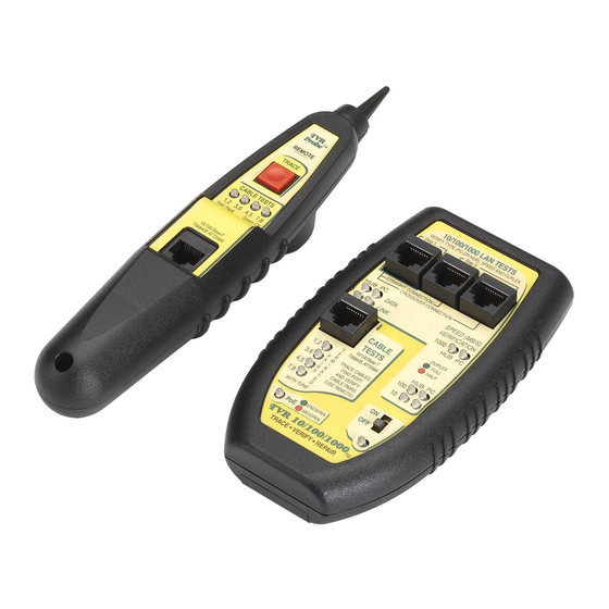
Section III. Faceplate Description. 10/100/1000 LAN TESTS The following tests utilize these 3 sockets. SPEED/DUPLEX LEDs... Shows 10,100 and/or 1000 MB/s. Color shows full or half duplex. Single port and inline mode. DATA/LINK LEDs...Verifies the device type (hub/switch or PC) and presence of Data packets and/or Link pulses. -
Page 7: Section Iv Learning The Main Unit's Faceplate
Section IV. Learning the Main Unit's Faceplate communications, so the TVR1000 can be used to continuously monitor the link for data and link activity plus speed and duplex. The TVR1000 Main Unit can be connected to a single port of any Understanding the use of the 10, 100 or 1000 Base-T device and it can be inserted inline between 10/100/1000 LAN Test’s... -
Page 8: Single Port Testing
Single Port testing Inline testing Use the Green jack to verify the device type Use the three jacks to determine the as a hub/switch or a PC; the presence of negotiated speed and duplex between any Data and Link pulses; and the complete two LAN devices. - Page 9 Keeping in mind the above, the following applies: testing) are the same for Inline testing. The speed/duplex indicated is the result of the two devices negotiating to a common speed and If the TVR1000 is connected to only one LAN device, it will ●...
-
Page 10: Section V. Learning The Remote Probe's Faceplate
Section V. Learning the Remote Probe's Faceplate CABLE TESTS Jack The TVR1000’s Remote Probe adds cable tracing and The Cable Test section of the Main Unit pairs testing capability to the TVR1000. It must be used is an easy-to-use and very powerful with the Main Unit’s Cable Tests jack. - Page 11 (using the Main Unit’s Cable Test jack) and tracing it using The same jack that transmits the tone) and displays the results of the Remote Probe. The remote Probe will emit a tone when it is close to decoding on the Remote Probe’s four LEDs. The LEDs meaning is (or touching) the cable under test.
-
Page 12: Section Vi. Performing Lan Tests
Section VI. Performing LAN Tests Plug into What follows are a few examples of using the TVR1000 to perform green jack typical network troubleshooting. With a little experience, you will be adding your own new tests. If you are new to LAN testing, please read the “Introduction”, “The Three Phases of LAN installation”, Appendix A, Appendix B and Appendix C of this manual. - Page 13 Step 4: SPEED/DUPLEX TEST: The data rate(s) of 10,100 and Test example #1. Using a Single Port test to determine a PC or Hub/Switch's capabilities. This procedure tests if a LAN port is 1000 MB/s are displayed on the Main Unit’s “SPEED VERIFICA- TION”...
- Page 14 If the data rate is less than you expect (e.g. a 100 MB/s communi- allow a minimum of 3 seconds between connections (this is the time cating at 10 MB/s), look for one of these problems: it takes the TVR1000 to make a reading). The LAN device is a 10 Base-T port only.
- Page 15 the negotiated speed/duplex of the two devices is slower than the If only one column of LEDs comes on in either jack configuration speed/duplex of each individual device (you determine the speed you are not communicating. If this is the case, unplug both devices and duplex of the individual devices by plugging them separately from the TVR1000 and then test the devices individually using the into the Green jack as shown in the Single Port test of Example#1).
- Page 16 between) and test. You should see activity (a Data/Link LED) and a Test example #3. Testing a 100 MB/s switch port for an un- Speed/Duplex LED. If you don't, the LAN device is faulty. If you do, known problem at far end of the cable (not at the switch port). the cable is faulty.
-
Page 17: Test Example #6. Testing A Cable's Pair Configuration
senses if the far device is connected to the cable by searching for “7,8’). Listening to the missing gaps in the tone signal can some- continuity through the device. It does not matter if the far device is times be helpful in understanding a problem. powered-up or not. -
Page 18: Appendix A. Wiring Primer
(see Appendix A). See note below for required pairs. Appendix A. Wiring Primer. INVERTED PAIRS: If any of the pairs are present but have incorrect polarity (i.e. the “1,2” pair is really “2,1”) the pair’s LED will light Twisted Pair Cable: Base-T LANs are based on a star topology red. - Page 19 Summary Twisted Pair (TP) Wire Connection Chart Twisted Pair cables connecting: PC to Hub/Switch Straight thru AT&T 258A (EIA/TIA 568B) STRAIGHT THRU PC to PC Crossover PIN # PIN # WIRE COLOR Hub/Sw to Hub/Switch Crossover 1 Orange/White 2 Orange Note: Because the Base-T standard has a mix of crossover and 3 Green/White straight thru cables, many opportunities arise for the pairs to get...
- Page 20 AT&T 258A (EIA/TIA 568B) Signal Definition in Diagram Form Twisted Pair Cables TP cable is used for Base-T applications be- cause of its excellent noise cancelling capabilities. Two pairs of twisted PIN # POLARITY FUNCTION Pair 2 pair wire are the minimum required for each computer that hooks to (+) Transmit Data the hub or switch : (-) Receive Data...
-
Page 21: Appendix B. 10, 100 And 1000 Base-T Basics
Appendix B. 10, 100 and 1000 Base-T Basics RJ45 Connectors (sockets and plugs): The Base-T Standard uses RJ45 sockets and plugs. The RJ45 socket has 8 pins. The pins Base-T LANs connect LAN devices (PCs, hubs and switches) to are numbered 1 to 8. Looking at the socket with insertion key facing other LAN devices using twisted pair cable. - Page 22 "Hub", "Switch" and "PC" defined: A “PC” is a device that some devices are programmable, allowing you to "force" their speed and duplex. "Forced" devices, likewise, may not send link pulses. transmits on a pair of wires that use pins 1 and 2 (“1,2”). A “hub” and Because the TVR1000 uses link pulses to determine the speed and "switch"...
-
Page 23: Appendix C. Ways To Minimize Lan Problems
Appendix C. Ways to minimize LAN problems. If there is a short or open on pairs 1,2 and 3,6 all communications will be prevented. If there is a short or open on pairs 4,5 or 7,8 the data rate may drop. Use Category 5E cable (rated at 1000 MB/s). -
Page 24: Appendix D. Self-Test And Battery Replacement
Appendix D. Self test and battery replacement Testing the Main Unit: The “10/100/1000 LAN Test” section of the Main Unit is equipped with a self-test feature that is automati- cally activated when the unit is powered ON. Self-test progress is indicated by a series of sequentially flashing LEDs.