Lennox ML180DFE Series Unit Information
Hide thumbs
Also See for ML180DFE Series:
- User's information manual (7 pages) ,
- Installation instructions manual (35 pages) ,
- Installation instructions manual (30 pages)
Table of Contents
Advertisement
Quick Links
S e r v i c e L i t e r a t u r e
ML180DFE series units are mid-efficiency gas furnaces
used for downflow applications only, manufactured with
Lennox Duralok heat exchangers formed of aluminized
steel. ML180DFE units are available in heating capacities
of 44,000 to 110,000 Btuh and cooling applications 1.5 to
5 tons. Refer to Engineering Handbook for proper sizing.
Units are factory equipped for use with natural gas. Kits
are available for conversion to LP/Propane operation.
ML180DFE model units are equipped with a hot surface
ignition system and a constant torque ECM motor. The
motor is programmed to provide constant torque at each
of the five selectable speed taps. All units use a redundant
gas valve to assure safety shut-off as required by C.S.A.
All specifications in this manual are subject to change.
Procedures outlined in this manual are presented as a
recommendation only and do not supersede or replace lo-
cal or state codes. In the absence of local or state codes,
the guidelines and procedures outlined in this manual
(except where noted) are recommended only and do not
constitute code.
CAUTION
As with any mechanical equipment, contact with
sharp sheet metal edges can result in personal
injury. Take care while handling this equipment and
wear gloves and protective clothing.
TABLE OF CONTENTS
Specification ..........................................................Page 2
Blower Data............................................................Page 3
Parts Identification .................................................Page 5
I Unit Components ................................................Page 6
II Installation.........................................................Page 19
III Start Up............................................................Page 19
IV Heating System Service Checks ..................Page 19
V Typical Operating Characteristics ..................Page 22
VI Maintenance....................................................Page 23
VII Wiring and Sequence of Operation................Page 27
UNIT INFORMATION
UNIT INFORMATION
Corp 1121-L4
Revised 04/2022
ML180DFE SERIES UNITS
Page 1
WARNING
Electric shock hazard. Can cause injury
or death. Before attempting to perform
any service or maintenance, turn the
electrical power to unit OFF at disconnect
switch(es). Unit may have multiple power
supplies.
WARNING
Improper
installation,
service or maintenance can cause property damage,
personal injury or loss of life. Installation and service
must
be performed by a licensed professional
HVAC installer or equivalent, service agency, or the
gas supplier.
ML180DFE
adjustment,
alteration,
©2016 Lennox Industries, Inc.
Advertisement
Table of Contents

Related Manuals for Lennox ML180DFE Series


Summary of Contents for Lennox ML180DFE Series
-
Page 1: Table Of Contents
S e r v i c e L i t e r a t u r e Revised 04/2022 ML180DFE SERIES UNITS ML180DFE series units are mid-efficiency gas furnaces used for downflow applications only, manufactured with Lennox Duralok heat exchangers formed of aluminized steel. -
Page 2: Specification
SP ECIF ICATIONS Model No. ML180DF045E36A ML180DF070E36A ML180DF070E36B Heating AFUE Performance Input - Btuh 44,000 66,000 66,000 Output - Btuh 36,000 54,000 54,000 Temperature rise range - °F 15 - 45 30 - 60 30 - 60 Gas Manifold Pressure (in. w.g.) 3.5 / 10.0 3.5 / 10.0 3.5 / 10.0... -
Page 3: Blower Data
OPT IONAL AC C ESSORIES - ORD ER SEPARAT ELY “A” Width “B” Width “C” Width Models Models Models CABINET ACCESSORIES Downflow Combustible Flooring Base 11M59 11M60 11M61 CONTROLS iComfort M30 Smart Wi-Fi Thermostat 15Z69 15Z69 15Z69 ® Remote Outdoor Air Temperature Sensor X2658 X2658 X2658... - Page 4 BLO WER DATA ML180DF070E36B PERFORMANCE (Less Filter) Air Volume / Watts at Various Blower Speeds External High Medium-High Medium Medium-Low Static (Black) (Brown) (Blue) (Yellow) (Red) Pressure in. w.g. Watts Watts Watts Watts Watts 0.00 0.10 1430 1275 1190 1155 1005 0.20 1400...
-
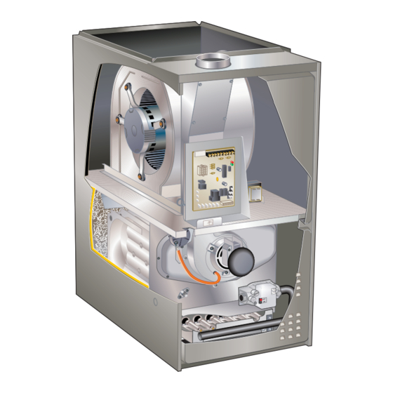
Page 5: Parts Identification
PARTS ARRANGEMENT Secondary Limit Blower Assembly Flue Chase Control Box (includes integrated control, interlock switch and transformer) Blower Access Panel Heat Exchanger Combustion Air Inducer Primary Limit (under combustion air inducer) Gas Valve Burner Box (includes sensor, ignitor Heating Compartment and rollout switches) Access Panel FIGURE 1... -
Page 6: I Unit Components
I-UNIT COMPONENTS 4. Integrated Control (A92) 103217-03 & 107163-01 Unit components are shown in figure 1.The gas valve, combustion air inducer and burners can be accessed by WARNING removing the upper access panel. Electrical components are in the control box (figure 2) found in the blower section. Shock hazard. - Page 7 TABLE 1 4-Pin Terminal Designation IGNITION CONTROL 103217-03 PIN # FUNCTION Combustion Air Inducer Line Ignitor Line Combustion Air Inducer Neutral Ignitor Neutral TABLE 2 12-Pin Terminal Designations PIN # FUNCTION High Limit Output IFC 103217-03 Not Used IFC 107163-01 Flame Sense 24V Line Not Used Rollout Switch Out...
- Page 8 TABLE 4 Ignition Control 103217-02 RED LED Diagnostic Codes / Status of Furnace Flash Code No power to control or board fault detected Heartbeat Normal Operation - Idle, Continuous Fan, Cool Reverse Line Voltage Polarity Improper Earth Ground Burner failed to light, or lost flame during heat demand Low Flame Signal - check flame sensor Watchguard - burner failed to light, exceeded maximum number of retries or recycles.
- Page 9 TABLE 5 Ignition Control 103217-03 RED LED Diagnostic Codes / Status of Furnace Flash Code No power to control or board fault detected Heartbeat Normal Operation - Idle, Continuous Fan, Cool Continuous Rapid Flash Call For Heat / Burner Operation Reverse Line Voltage Polarity Improper Earth Ground Burner failed to light, or lost flame during heat demand...
- Page 10 Ignition Control 107163-01 RED LED Flash Code Diagnostic Codes / Status of Furnace No Power to Control or Board Fault Detected Board Fault Detected Fast Heartbeat Call for Heat / Burner Operation Slow Heartbeat Normal Operation – Idle, Continuous Fan, or Cool 1 Flash Reverse Line Voltage Polarity or Phasing of 120V power 2 Flashes...
- Page 11 ELECTRONIC IGNITION 5 SEC Trial for Pre -Purge Ignitor Warm-up Blower “On”* Post Ignition Delay Purge DEMAND IGNITOR GAS VALVE INDOOR BLOWER *Blower on time will be 30 seconds after flame is sensed. Blower off time will depend on “OFF TIME” Setting. FIGURE 4 Fan Time Control HEAT FAN OFF TIME IN SECONDS...
- Page 12 7 - When main burners are in operation for two minutes, a different setpoint for each unit model number. If limit take reading. switch must be replaced, refer to Lennox ProductZone re- pair parts list. TABLE 6 7. Flame Sensor (Figure 6)
- Page 13 Measuring Flame Signal (Typical Furnace and Control) Remove Sensor Wire from Flame Integrated Control and Sensor Connect Alligator Clip (−) to Flame Sensor Lead Flame Sensor Wire DIGITAL METER Set dial to measure dc microamps Integrated Control Red Collar Indicates Positive Lead Flame Sensor...
- Page 14 8. Ignitor (Figure 6) NOTE - The ML180UDFE(X) furnace contains electronic components that are polarity sensitive. Make sure that the The nitride ignitor used units is made from a proprietary furnace is wired correctly and is properly grounded. ceramic material. To check ignitor, measure its resistance and voltage.
- Page 15 LPG bustion air inducer is not operating or if the flue becomes changeover kits are available from Lennox. Kits include obstructed. burner orifices and a gas valve regulator spring.
- Page 16 12. Blower Motor BLOWER WHEEL REPLACEMENT IMPORTANT Center Blower Wheel in Blower Housing Each blower is statically and dynamically balanced as an assembly before installation in the unit. ML180DFE units are equipped with a constant torque ECM motor. It has a DC motor coupled to an electronic control module both contained in the same motor housing.
- Page 17 Multi−Meter (set to VAC) Multi−Meter (set to VAC) Test 1 Test 3 (if necesssary) Turn on power to unit. Check for 120 volts across terminals Check for 120 volts across terminals “CIRC” and “Neutrals” “L” and “N” on input plug P48. If voltage is present continue on the integrated control.
- Page 18 Replacing the Motor Module Motor Test 1 - Disconnect electrical power to unit. 2 - Remove unit access panel. 3 - Unplug the two harnesses from the motor control module. See figure 14. Unplug the Two Harness Connection TWO HARNESS CONNECTIONS MOTOR MOTOR CONTROL MODULE...
-
Page 19: Installation
II- PLACEMENT AND INSTALLATION Turning Off Gas to Unit 1 - Set the thermostat to the lowest setting. Make sure unit is installed in accordance with installation instructions and applicable codes. 2 - Turn off all electrical power to the unit if service is to be performed. - Page 20 3 - While waiting for the unit to stabilize, observe the specialty Gas Leak Detector is strongly recommended. It is available through Lennox under part number 31B2001. flame. Flame should be stable and should not lift See Corp. 8411-L10, for further details.
- Page 21 TABLE 12 Manifold Pressure Settings at all Altitudes Line Pressure in. wg. Model 7501 - 10,000 0 - 4500 ft. 4501 - 7500 ft . Input Size 13.0 LP/Propane 10.0 10.0 10.0 11.0 13.0 13.0 LP/Propane 10.0 10.0 10.0 11.0 13.0 13.0 LP/Propane...
-
Page 22: Typical Operating Characteristics
H- Proper Ground and Voltage TABLE 14 A poorly grounded furnace can contribute to poor flame Measurement VAC Furnace Status sense signal. Use the following procedure to check for Expected Maximum ground and voltage to the integrated control. Power on Furnace Idle 1 - Measure the AC voltage between Line Neutral CAI/Ignitor Energized 0.75... -
Page 23: Maintenance
At the beginning of each heating season, and to comply system. On ducted systems, connect the other end with the Lennox Limited Warranty, your system should of manometer to the return duct as above. be checked by a licensed professional technician (or... - Page 24 Before using any filter with this system, check the furnace inspection to ensure proper combustion specifications provided by the filter manufacturer and operation. Consult Service Literature for proper against the data given in the appropriate Lennox combustion values. Product Specifications bulletin.
- Page 25 Cleaning the Heat Exchanger and Burners 6 - Disconnect gas supply piping. Remove the four screws securing the burner manifold assembly to NOTE - Use papers or protective covering in front of the the vestibule panel and remove the assembly from furnace during cleaning.
- Page 26 11 - To clean the combustion air inducer visually inspect Remove five screws if necessary and using a wire brush clean where necessary. Use (either side of cabinet) compressed air to clean off debris and any rust. 12 - Reinstall heat exchanger in vestibule. (Replace the five screws in the cabinet from step 10 if removed).
-
Page 27: Wiring And Sequence Of Operation
VII- Wiring and Sequence of Operation Schematic Wiring Diagram and Sequence of Operation Line voltage is applied to L1 and N. the T1 low voltage transformer is energized, and line voltage is applied to B3 indoor blower. S47 rollout switch(es) must be closed in order for 24V from transformer to be output on integrated control ”R” to power thermostat. When there is a call for heat, W1 of the thermostat energizes W of the furnace control with 24VAC. - Page 28 HEATING SEQUENCE OF OPERATION ABNORMAL HEATING MODE NORMAL HEATING MODE POWER ON GAS VALVE OFF. COMBUSTION AIR INDUCER OFF. INDOOR BLOWER DELAY OFF. CONTROL SELF-CHECK OKAY? LED SLOW FLASH (RESET CONTROL BY TURNING MAIN POWER OFF.) LED FLASHES CODE 1 - POLARITY REVERSED. IS POLARITY CORRECT? LED FLASHES CODE 2 - IMPROPER GROUND.
- Page 29 HEATING SEQUENCE CONTINUED 15 SECOND COMBUSTION AIR INDUCER PREPURGE INITIATED BY CLOSED PRESSURE SWITCH. LED FLASHES CODE 13 - LOW LINE VOLTAGE. ONCE VOLTAGE IS ABOVE IS VOLTAGE ABOVE 70 VOLTS? IGNITOR WARM UP -- 20 SECONDS. 75 VOLTS, HEATING SEQUENCE RESTARTS.
- Page 30 COOLING SEQUENCE OF OPERATION POWER ON IGNITION CONTROL MAIN POWER ON. GAS VALVE OFF. COMBUSTION AIR INDUCER OFF. INDOOR BLOWER OFF WITH NORMAL DELAY. CONTROL SELF DIAGNOSTIC CHECK. SIGNAL CIRCUIT BOARD FAILURE AT LED. IS CONTROL OPERATING NORMALLY? INTERRUPT MAIN POWER TO RESET CONTROL. LED FLASHES CODE 2 IMPROPER GROUND IS THERE A PROPER GROUND? CONTROL WILL CONTINUE TO CALL FOR COOLING...
- Page 31 CONTINUOUS FAN SEQUENCE OF OPERATION LED: SLOW FLASH RATE REMAINS UNCHANGED THROUGHOUT SEQUENCE. MANUAL FAN SELECTION MADE AT THERMOSTAT. CONTROL (G) ENERGIZES SYSTEM FAN AT FAN SPEED. EAC TERMINAL IS ENERGIZED. THERMOSTAT CALLS FOR HEAT (W). SYSTEM FAN CONTINUES FAN SPEED WITHOUT THERMOSTAT CALLS FOR COOLING.