Advertisement
Quick Links
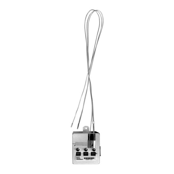
Installing an Auxiliary Pressure
Control Module
Agilent 6850 GCs
Accessory G3349B
This kit contains:
Description
Cable tie .062-.625 diameter
Hex nut w/lockwasher
Disposable wrist strap
Minifold label
Restrictor kit
•
FID air restrictor (brown)
•
Blue dot restrictor
•
O-rings (6 pk)
•
Tube zero restrictor
•
External H
flow limiter
2
•
External Flow Restrictor Install Guide
Aux. press. control module assembly (with covers)
Back panel replacement for the GC
6850 GC user information CD
ChemStation software CD
Installation sheet (this document)
The module is factory-assembled. Do not disassemble it during installation.
Quantity
2
1
1
1
1
3
3
1
3
2
1
1
1
1
1
1
Advertisement

Related Manuals for Agilent Technologies 6850 GCs


Summary of Contents for Agilent Technologies 6850 GCs
- Page 1 Installing an Auxiliary Pressure Control Module Agilent 6850 GCs Accessory G3349B This kit contains: Description Quantity Cable tie .062-.625 diameter Hex nut w/lockwasher Disposable wrist strap Minifold label Restrictor kit • FID air restrictor (brown) • Blue dot restrictor •...
-
Page 2: Parts Identification
Installing an Auxiliary Pressure Control Module Parts identification Parts identification Hex nut w/lockwasher Minifold label Aux. pressure control module assembly... -
Page 3: Required Tools
Installing an Auxiliary Pressure Control Module Required tools Required tools ® • Torx T-20 screwdriver • Needle-nose pliers Overview Caution Before starting, review the safety information listed at the end of this document. Disconnect the GC. Install the new module. Restore the GC to operating condition. - Page 4 Installing an Auxiliary Pressure Control Module Disconnect the GC Disconnect the GC WARNING Hydrogen gas is flammable and potentially explosive. Before replacing the module, turn off the hydrogen gas at the source. Turn off the GC and unplug the power cord. Allow time for all heated zones to cool.
- Page 5 Installing an Auxiliary Pressure Control Module Install the new module Remove the seven T-20 screws on the back panel. Save the screws. Remove Tilt the top of the panel away from the GC. If you have a Series II GC, save this panel. Otherwise, set this panel aside because you will no longer use it.
- Page 6 Installing an Auxiliary Pressure Control Module Install the new module If you will be using the back panel from the kit, use needle-nose pliers to remove the knockouts for the ribbon cable and power cable slots. Ribbon cable slot Low voltage power High voltage power Remove the tape from around the new control module and thread the ribbon cable through the slot in the back panel.
- Page 7 Installing an Auxiliary Pressure Control Module Install the new module Gather the excess gas tubing from the gang fitting block in a loop and tie it together with a cable tie. Cable tie Gas tubing Attach the control module to the back panel by hooking the tabs on the module just inside the ribbon cable slot.
- Page 8 Installing an Auxiliary Pressure Control Module Install the new module Changing the flow restrictors (optional) The auxiliary channels are controlled by a pressure setpoint. To work properly, there must be adequate flow resistance downstream of the pressure sensor. The auxiliary channel pneumatics manifold provides a frit- type restrictor for each channel.
- Page 9 Installing an Auxiliary Pressure Control Module Install the new module (Ambient conditions: 25°C, 14.7 psia) 19234-60660 (blue dot) 19231-60770 (red dot) Minimum source pressure (psig) 19231-60610 (brown dot) 10.0 100.0 1000.0 Gas Flow in mL/min Figure 1. Pressure requirements for AUX EPC flow restrictors with air, nitrogen, or helium...
- Page 10 Installing an Auxiliary Pressure Control Module Install the new module (Ambient conditions: 25°C, 14.7 psia) 19234-60660 (blue dot) Minimum 19231-60770 source (red dot) pressure (psig) 19231-60610 (brown dot) 10.0 100.0 1000.0 Gas Flow in mL/min Figure 2. Pressure requirements for AUX EPC flow restrictors with hydrogen...
- Page 11 Installing an Auxiliary Pressure Control Module Install the new module Changing an auxiliary channel frit Locate the gang fitting block. It connects the three gas outlet tubes for the auxiliary channels to the pneumatics module. Gang fitting block Remove the screw that holds the block to the pneumatics module. Pull the block free of the module and rotate it so that the frits are on top.
- Page 12 Installing an Auxiliary Pressure Control Module Restore the GC to operating condition Restore the GC to operating condition Reconnect all cables. Restore power. Display the Status / Settings / Auxiliary screen on the control module. If the module is installed correctly, this screen appears. An actual flow value appears when gases are off or not connected.
- Page 13 Installing an Auxiliary Pressure Control Module Restore the GC to operating condition...
- Page 14 Failure to comply with these precautions violates safety standards of design and the intended use of the instrument. Agilent Technologies assumes no liability for the customer’s failure to comply with these requirements.