
Related Manuals for Agilent Technologies 78581B


Summary of Contents for Agilent Technologies 78581B
- Page 1 Installation and Service Guide Agilent Serial Distribution Network (SDN) 78581B Agilent CareNet Controller (ACC) Part Number 78581-92000 Printed in the U.S.A. February 1, 2001 First Edition '$%"% (& ...
- Page 2 The information contained in this document is subject to change without notice. Agilent Technologies makes no warranty of any kind with regard to this material, including, but not limited to, the implied warranties or merchantability and fitness for a particular purpose.
-
Page 3: Table Of Contents
SDN Configurations ..........1-3 Agilent CareNet Controller (ACC), Model 78581B ......1-4 ACC Controls and Indicators . - Page 4 Typical SDN System Interconnecting Parts ......6-1 Installation Responsibilities—Customer and Agilent Technologies ... . . 6-3 Customer Installation Responsibilities .
- Page 5 ACC Procedures (78581B)........
- Page 6 9. SDN/ACC System Safety ........9-1 Compliance with IEC 60601-1-1 ......... . 9-1 Device Grounding on the SDN .
-
Page 7: Introduction
SDN Components The components of the SDN consist of the model 78581B Agilent CareNet Controller (ACC), the SDN interface circuitry located within each instrument connected to the SDN, and the system distribution cables (branch cables), local distribution cables, and the associated wallbox hardware, connectors and receptacles. - Page 8 SDN System Description words per 32-millisecond poll cycle. The SDN is a half-duplex network using terminated shielded twisted pair cable(s). All data is transmitted differentially and serially using block code modulation. A detailed description of the SDN system theory of operation is given in a subsequent section of this manual.
-
Page 9: Operating Reliability - Failure/Restart
Introduction CCU/PCU 4 Bedsides Tele Mainframe 4 Bedsides 4 Telepaks 4 Telepaks Figure 1-2. Typical SDN Configuration Operating Reliability — Failure/Restart Power Failure: ACC operation resumes automatically after power restoration. Loss of power to the ACC will not affect local operation between instruments on a branch that do have power. -
Page 10: Agilent Carenet Controller (Acc), Model 78581B
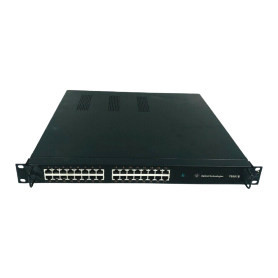
The ACC consists of a metal chassis with cover, a Power Supply Assembly, a Terminal Interconnect PC board, and a Control/Driver PC board. The model 78581B Agilent CareNet Controller is illustrated on in Figure 1-3 on page 1-5. The Control/Driver PC board contains all the electronic circuitry required to control the data flow, timing, and distribution of SDN data throughout the system. -
Page 11: Acc Controls And Indicators
Power comes on as soon as it’s connected to AC by power cord. To disconnect the power, remove the plug from the wall receptacle. Figure 1-3. Agilent 78581B Agilent CareNet Controller ACC Controls and Indicators There are no operator controls located on the ACC. Once the power cord is connected and the ACC is running properly, no operator adjustments are necessary. -
Page 12: Cables, Wall Boxes, And Faceplates
(KOs) may be used. The depth of the wall box must be at least 7.0 cm (2.75 in). Wall boxes are usually supplied by the customer; however, two types are available from Agilent Technologies. Face Plates: Pre-punched, NEMA, single- or dual-gang faceplates for the SDN;... -
Page 13: Sdn Components
Installation of a complete Serial Distribution Network requires the ordering and selection of several instruments, SDN system components and options. These include the model 78581B ACC and options from the 78599AI/Cabling Installation Kit to provide Local Distribution Cables (LDC) and connector hardware. Branch cables are ordered separately using their associated Agilent part number. -
Page 14: M3199Ai Installation Materials
Intended Use of Device — JJ1 SDN on UTP parts (European) Quantity 1 — JJ2 SDN on UTP parts (European) Quantity 8 — J03 3-Foot Local Distribution Cable (LDC)(81 20-3591) — J06 6-Foot Local Distribution Cable (LDC)(81 20-3587) — J10 10-Foot Local Distribution Cable (LDC)(8120-3588) —... -
Page 15: Theory Of Operation
Theory of Operation Section 2: Theory of Operation Overview Theory of operation consists of two distinct subsections: • SDN Theory of Operation • ACC Theory of Operation SDN Theory of Operation describes the overall system Serial Distribution Network (SDN), its normal operating characteristics, applications, and error conditions, the format of the SDN digital data, and the SDN system communications protocol as well as the local distribution network (LDN) communications protocol. -
Page 16: Sdn Theory Of Operation
SDN Theory of Operation SDN Theory of Operation SDN General Description The Serial Distribution Network (SDN) is a digital communications network designed to share patient physiological parameters and other data among all instruments connected directly to the SDN. The SDN uses cables containing a twisted shielded pair of wires to connect the instruments to the Agilent CareNet Controller (ACC). -
Page 17: Logic Convention
Theory of Operation Term Definition Shielded Twisted Pair A cable containing two wires which carry all digital Custom Cable data on the SDN. The two wires are twisted together to minimize interference from magnetic fields, and encased in a braided shield to limit interference from electrostatic fields. - Page 18 SDN Theory of Operation SDN Quiescent State Pink wire biased O.4V more negatively than blue wire. Data wires are quiescent during dead time. Data Wires (LDC only) Positive (+) Wire Pink colored wire Negative (–) Wire Blue colored wire Priority Wires (LDC only) Positive (+) Wire Gray colored wire Negative (–) Wire...
-
Page 19: Sdn Topology
Theory of Operation SDN Topology The SDN uses a star topology that consists of up to 32 individual branches emanating from the center of the star—the ACC. Only one ACC may be used per SDN. One SDN can accommodate up to 24 bedside instruments (one patient per branch), 6 information centers (ICs), and 2 computerized monitoring systems. -
Page 20: Applications Of Sdn Operation
Applications of SDN Operation Applications of SDN Operation Configurations of the SDN will vary from installation to installation. The SDN is designed to be flexible enough to accommodate a variety of communication needs in the patient monitoring environment, for the present and for future expansion. -
Page 21: Sdn Timing Overview
Theory of Operation the branch cables for instrument-to-system communication via the ACC, and also over the local distribution cable(s) for instrument-to-instrument communication when the local distribution network (LDN) exists. Only one instrument broadcasts patient data at a time and the ACC rebroadcasts that information from that branch to all other branches on the system. -
Page 22: Autopoll Mode
SDN Data Structure — System and Instrument Messages Autopoll Mode In the event that the ACC goes down (loses power, for example), all instruments on the same branch continue to communicate with each other in the autopoll mode. Autopoll means that the first instrument (closest to the wall box) sends sync taps and talk taps to itself and the other instruments on the branch. -
Page 23: Instrument Messages
Theory of Operation Talk Tap: The talk tap carries encoded information to indicate the branch number and to identify the “autopoll” operating mode. Note Since the status information is block encoded, there is not a one-to-one correspondence between status values and bits of the status words. The condition of these bits are indicated on the status LEDs on the ACC and on the display screens of the SDN instruments. -
Page 24: Sdn Normal Operation
SDN Normal Operation SDN Normal Operation This section contains the SDN data timing specifications and a description of the instrument status message. SDN Data Timing Specifications During normal operation SDN digital data travels on the SDN at 3.6 Mbit; the bit cell width is 1/3,600,000 seconds, or 277.78 ns. 277.78ns Bit Cell Width Therefore, the 12-bit word is 3.33 µs long. -
Page 25: Sdn/Autopoll
Theory of Operation a. Instrument Identification: Each instrument can be identified as any SDN bedside monitor, IC, or computer. For bedsides the instrument identification gives branch number and type of bedside monitor. b. SDN Communication Error Flags: A variety of SDN system errors are identified and flagged in the instrument status message. -
Page 26: Acc Error Conditions - Sdn Failure Detection
SDN Normal Operation ACC Error Conditions — SDN Failure Detection The functional operation of the ACC can be checked and verified to ensure reliable operation. During normal operation, the following LEDs on the Control/Driver PC board are illuminated continuously: RED DS1 (MSB) flickers RED DS4 (LSB) -
Page 27: Acc Theory Of Operation
Theory of Operation ACC Theory of Operation The ACC consists of three PC boards (refer to Figure 2-2): • Main PCB • Transition board assembly • Power supply Main PCB (78581-60200) The Main PCB is considered the control/drive board. It connects up to 32 branch cables via the Transition Board to provide timed multiplexed communication links and system synchronization. -
Page 28: Transition Board (78581-61253)
ACC Theory of Operation polled at the end of 32 milliseconds must be branch 31 for TALK TAP messages. If not, the poll cycle is in error and an error flag is set in the next SYNC TAP message to indicate a POLL OVERLFOW; for example, system overload or poll sync loss. -
Page 29: Sdn And Acc System Level Troubleshooting
SDN and ACC System Level Troubleshooting Section 3: SDN and ACC System Level Troubleshooting Caution Service and repair of the SDN system components is to be performed by authorized service personnel only. SDN Troubleshooting Overview This section describes a logical approach for service personnel to diagnose and identify the source of an SDN system problem and to isolate the problem to the instrument/cable level for service and/or repair. - Page 30 SDN Troubleshooting Overview In addition, service personnel must be aware of the structure of the SDN system being troubleshot with respect to: • Care Units • Bed Label/Branch Assignments • IC Tuning • IC/Branch Assignments The following abbreviations are used throughout this section: •...
-
Page 31: Troubleshooting Resources, Tools, And Equipment
SDN and ACC System Level Troubleshooting Troubleshooting Resources, Tools, and Equipment The following resources are available with the SDN instruments to facilitate troubleshooting the SDN system: • INOP Messages • Overview Function • Network Test • Self-Test Routines • Error Codes •... - Page 32 Troubleshooting Resources, Tools, and Equipment Figure 3-2. SDN System Troubleshooting Flowchart Start Step 1 Review system How many configuration. instruments on the Error branch are affected? Step 2 Troubleshoot Examine system. (and cable) 1. Check if SDN is connected. 2. Network Test, Self-Test. 3.
-
Page 33: Step #2: Examine System And Gather Symptoms
SDN and ACC System Level Troubleshooting ÿû ü ü õ ñõíü øôòù õú ôüÿ ôòõ ü ùð ñïøúëòñùð Obtain a basic understanding of the customer’s system architecture and topology, and familiarize yourself with the SDN configuration. Review the instrument branch assignments, care unit definitions, and IC tuning ranges. -
Page 34: Noisy Branch
Troubleshooting Resources, Tools, and Equipment Table 3-1: SDN Error Messages (Continued) SDN Error Messages Description NO OVERVIEW FUNCTIONS Monitor/terminal is not connected to the AVAILABLE SDN, or it is getting no signals from the ACC; i.e., it is operating in the Autopoll mode. NO DATA FROM BEDS IN UNIT In this Care Unit there are no beds in the same group as this bed and no beds in the All... -
Page 35: Sdn And Non-Sdn Related Problems
SDN and ACC System Level Troubleshooting 2. Check the FIRE AXE LED to see if it is still lit and then replace the RJ45 connector. 3. Check the next branch. SDN and Refer to the following table for SDN and non-SDN related problems. Non-SDN Related Problems SDN Related Problems... -
Page 36: Step #3: Evaluate The Breadth Of The Problem
Troubleshooting Resources, Tools, and Equipment STEP #3: Evaluate the Breadth of the Problem Decide whether this is a single branch problem or a multiple branch problem. Find out how many branches are unable to communicate properly on the SDN; how many branches are unable to receive data from any other instrument and/or unable to transmit data to any other instrument. - Page 37 SDN and ACC System Level Troubleshooting Possible Source of Problem M/T or IC Wall Box Branch Specific Circuitry Interface in the ACC Figure 3-3. SDN Interface Problem Area If not already done, run the instrument’s self-test on each SDN instrument on the faulty branch.
- Page 38 Troubleshooting Resources, Tools, and Equipment M/T or IC Wall Box Interface Figure 3-5. SDN Non-Instrument Malfunction • If the problem affects only one instrument or all the instruments on the branch, go to STEP #5. • If the problem does not affect all instruments on the branch, it can be concluded that the ACC and cabling running up to, but not including the last “good”...
-
Page 39: Step #5: Isolating A Problem On A Local Distribution Network (Ldn) With Two Or More Instruments
SDN and ACC System Level Troubleshooting Warning Warning — Reconnection Warning — Disconnect SDN patient before swapping: Disconnect the patient from the monitor/terminal before swapping branches in the ACC. EXTEND TEST mode can be used to generate waveforms for verification. Caution CAUTION —... -
Page 40: Miscellaneous Items
Hospital ground may not meet the system specification. If this is suspected, refer to the ground check procedure on page 3-13. d. The hospital has installed cables (other than Agilent Technologies SDN or Agilent Technologies Analog cables) in violation of Agilent Technologies distance and shielding specifications. -
Page 41: Reverification Instructions
SDN and ACC System Level Troubleshooting STEP #3: Run Network Test: Evaluate breadth of problem (more than one branch = ACC problem) STEP #4: One branch: run instrument self-test to check SDN interface and isolate to ACC or local distribution network STEP #5: Isolate to one instrument on Local Distribution Network Reverification Instructions Three forms of communication should be verified: reception, transmission,... -
Page 42: Hardware Problems
Troubleshooting Resources, Tools, and Equipment These procedures address the following problems: • Hardware problems • Shorts in data wires and priority wires • Opens in data wires and priority wires • Miswiring • Voltage levels (ACC drivers) • Cable identification •... -
Page 43: Sdn Bedside
SDN and ACC System Level Troubleshooting Verify Proper Operation With the ACC running and the instruments connected to the branch, of Priority Wires measure the priority wire voltage from the downstream connector on the last instrument—most downstream instrument—on the branch as indicated on the following connector pins. -
Page 44: Ground Check Procedure
Troubleshooting Resources, Tools, and Equipment 78534A Monitor/Terminal Pin B (–) Pin A (+) Priority Wire—Black Data Wire—Pink (negative) (positive) Pin E (–) Data Wire—Blue (negative) Pin C (+) Pin D (GND) Priority Wire—Gray Drain Wires—Ground (positive) Downstream Connector (gray) Figure 3-6. SDN Downstream Connector Gray Ground Check The maximum ground potential difference between the third wire ground Procedure... -
Page 45: Acc Maintenance
ACC Maintenance Section 4: ACC Maintenance ACC Maintenance The Agilent CareNet Controller (ACC) is a ROM-driven microprogrammed state machine self-contained on the Control/Driver PC board for ease of serviceability. Once installed and running properly, the ACC requires virtually no periodic maintenance or servicing. However, when an electrical problem is evident within the ACC, isolation of the problem and repair can be accomplished using the troubleshooting procedures and self-test routines listed in Section 3: SDN and ACC System Level Troubleshooting. - Page 46 ACC Maintenance...
-
Page 47: Parts List
Parts List Section 5: Parts List Part Numbers Wall Box Minimum Depth = 2-3/4 in. Figure 5-1. SDN Faceplate/Connector Kits-Component Locations (78599AI-J01, JO2, and J53) Single Gang Dual Gang 78581-00150 78581-00160 Figure 5-2. SDN Faceplates, Single- or Dual-Gang... - Page 48 Part Numbers Jade Cocoa Gray Brown 3 ft. 78599AI-J03 (8120-3591) 6 ft. 78599AI-J06 Figure 5-3. Standard Length Local Distribution Cables (LDC) Figure 5-4. Power Supply Assembly (M2604-60002) Solid Backshell Cable Clamp Upstream Male Plug Connector Figure 5-5. Variable Length LDC Kit (78599A-J50)
- Page 49 Parts List LDC Cable Not Included in Kit Upstream Male Plug Cable Solid Connector Clamp Backshell Order Cable Downstream Separately Male Plug AS 78599AI-J54 Connector Figure 5-6. Connector LDC Kit (78599AI-J52) Pink Wire Filler Strips Braided Shield SDC or SXDC Blue Wire Drain...
- Page 50 Part Numbers M3199AI RJ45 Option J03 (78581-60350) Connector Blue Wire Drain Wire Pink Wire SDC or SXDC Braided Shield Connector Components Included in J52 Kit Figure 5-8. SDC and XSDC System Distribution Cables with M3199AI Option J03 for Runs Longer than Allowed with UTP Cable Part Number Description 78581-68200...
-
Page 51: Component Installation And Disassembly Procedures
SDN and ACC parts, and specifications. Caution Cables and parts supplied by Agilent Technologies, Inc. must be used in the installation of the SDN system, or the warranty may be void. This installation section describes the site preparation and installation responsibilities as well as the detailed installation instructions for installing the parts of the SDN. -
Page 52: Installation Responsibilities-Customer And Agilent Technologies
Installation Responsibilities—Customer and Agilent Technologies 110 Edge Connector Wall Box (USA) Wall Box (European) Monitor Branch Connected Cables with LDC Figure 6-1. Component Parts of a Typical SDN System Installation Responsibilities—Customer and Agilent Technologies The site preparation installation responsibilities for installing the component parts of the SDN are outlined below. -
Page 53: Agilent Installation Responsibilities
Supply certification of Category 5 UTP installation to Agilent installer. • Ensure cable installation conforms to local building codes. • Schedule Agilent Technologies service personnel to interconnect parts and instruments of the SDN. • Schedule key operator training for SDN system operation. Agilent Installation Responsibilities •... - Page 54 Installation Responsibilities—Customer and Agilent Technologies...
-
Page 55: Site Preparation/Installation Checklists
Site Preparation/Installation Checklists Section 7: Site Preparation/ Installation Checklists Introduction The following pages contain the checklists for site preparation and installation. - Page 56 (16 in. H x 20 in. W x 3/4 in. D) minimum for wall mounting. If rack mounting, architect aware that 19" telecommunications rack supplied. Architect aware that Agilent Technologies supplies bedside and Information Center switch wall box faceplates with LDC connector kits.
- Page 57 Site Preparation/Installation Checklists Architect aware that individual 3-wire AC outlets are recommended for each beside instrument, each Information Center, computer, and the ACC. Cables have been identified by bed number or remote site number and ordered after cable length from point-to-point has been carefully measured by the hospital.
- Page 58 Plant engineer/electrician/architect aware that no other wires should be run in the same conduit with signal cables. Plant engineer aware that installation of Agilent Technologies supplied wall mounts is the responsibility of the hospital. Plant engineer/electrician/architect aware that AC power diathermy cables, and so on should be run far enough away from site to prevent interference—at least 0.3 m (1 ft.) away.
- Page 59 Site Preparation/Installation Checklists Plant engineer aware that LAN cable must be Cat. 5, installed, and certified. Plant engineer/electrician aware of the number and location of AC power 3-wire (one ground wire) outlets. Note Each IC requires two AC outlets and each recorder or hard copier requires one AC outlet.
- Page 60 NEMA switch wall boxes. Builder aware that Agilent Technologies will supply SDN Agilent CareNet Controller (ACC). Builder aware that Agilent Technologies may supply SDN or LAN cables. Builder aware of mounting requirements of brackets and shelves if these are to be used.
- Page 61 Site Preparation/Installation Checklists Hospital Representative Checklist Prior to Installation Building Route from receiving dock to system site can accommodate equipment (ceilings, stairways, corridors, elevators, and so on). Area Layout Floor plan has been established and permits access to equipment for service and operation. Storage area is available for manuals, accessories, and consumables.
-
Page 62: Verification Procedures
Verification Procedures Verification Procedures Overview of SDN/ACC Installation and System Communication Verification Procedures The following overview depicts the recommended order of on-site customer engineering activities during SDN/ACC component installation. Refer to the associated section as indicated to perform the detailed installation procedures and follow the SDN/ACC installation procedures in the sequence indicated. -
Page 63: Installation
Installation Section 8: Installation SDN Installation SDN Wiring Installation UTP, SDC, or XSDC cables should be continuous from the location of the ACC to the wallbox. Refer to pages 8-11 through 8-16 for more information. Instrument Connection to the SDN Connect the instruments to their associated wall boxes using LDC cables. -
Page 64: Test And Inspection Procedures
SDN Installation “CONTINUOUS RECORDING” at top of screen, wait about five seconds and press the STOP softkey. Reset each IC and verify that there are no error codes. Examine the recorder strip to verify that ICs sharing the same recorder(s) are all on the same SDN branch. - Page 65 Figure 8-1. Main PCB Board LED Locations Has the secondary ground wire been attached to the Expected answer S:P or S:F Safety: 78581B? If “No” proceed to step 2 is passed Where P=Pass and Attach secondary ground if missing or visually F=Fail.
-
Page 66: When To Perform
SDN Installation When to Perform SERVICE EVENT Test Blocks Required Perform Visual, Power On, Performance, and Safety Test Installation Blocks Repair Perform Power On, and Performance Test Blocks. Main PCB Perform Power On, Performance, and Safety Test Blocks. Power Supply Upgrades Perform Power On, Performance, and Safety Test Blocks for Add additional branch... -
Page 67: Acc
Installation Note Do not daisy-chain Information Centers. • Branches #1 through #24 are dedicated for patient connected instruments (bedside monitors)—one patient per branch. • Branches #0, and #25 through #31 are dedicated for non-patient connected instruments (ICs and computer systems). •... -
Page 68: Wall Boxes
SDN Installation • Up to 2 local distribution cables (LDC) and 2 MFs may be daisy- chained to one branch (wall box). • The maximum total length of all LDCs on a branch must be less than 15 meters (50 feet). •... -
Page 69: Important Instructions
Installation Environmental The ACC mounting location must have adequate ventilation and air Conditions circulation, and be in a relatively dust/lint-free, static-free environment. The operating environmental characteristics of the ACC mounting location must conform to the environmental specifications listed. Temperature Range (ambient): Operating 0 C to 55 C (32 F to 131... -
Page 70: Acc Wall Mounting Procedures And Power Installation
ACC Wall Mounting Procedures It is Agilent Technologies’ responsibility to mount the ACC to the plywood panel at the chosen location. a. Orient the mount on the wall so that the ACC has its connection ports pointing towards either side. -
Page 71: Install Cable Enclosures, Wall Boxes, And Branch Cables
Installation Install Cable Enclosures, Wall Boxes, and Branch Cables It is the customer’s responsibility to install standard NEMA switch wall boxes, cable enclosures, and the required number of branch cables from the ACC to each wall box. Installation of the wall boxes and branch cables must be done in accordance with local and national building codes. -
Page 72: Formula
Install Cable Enclosures, Wall Boxes, and Branch Cables Table 8-1: Selecting Conduit Size Diameter (inches) Cross-sectional Cables Nominal Area (sq. inches) UTP Cables 0.196 0.03 SDN Cables: SDC, Part No. 8120-3502 0.34 0.09 XSDC, Part No. 8120- 0.44 0.15 3595 Conduit Sizes: 0.75 0.44... -
Page 73: Install Standard Nema Switch Wall Boxes
Branch cable runs must be continuous; do not splice cables or mix cable types. Caution Only branch cable supplied by Agilent Technologies may be used to interconnect the component parts of the SDN. No other type or brand of cable may be substituted, or the warranty may be void. -
Page 74: Sdc Standard System Distribution Cable
Install Cable Enclosures, Wall Boxes, and Branch Cables SDC Standard System Distribution Cable Maximum length per branch cable run: 152 meters (500 feet) SDC Cable Diameter: 0.8 cm (0.34 inch) dia. SDC Weight per 30.5 meters (100 feet): 2.9 kg (6.3 lbs) SDC Spool Lengths: 152-meter (500-ft.) —... - Page 75 Installation back the rest of the shield—at least 1.3 cm (1/2 inch)—OVER THE CABLE INSULATION. d. Remove the foil and filler strips from the cable end and separate the PINK, BLUE, and drain wires. e. Attach the drain wire to the GND terminal connector on the PC board/ SDN connector assembly.
- Page 76 Install Cable Enclosures, Wall Boxes, and Branch Cables correctly into the key slot of the shield cover and it is fastened securely. i. Place the cable insulation with folded back braided wire on the bottom edge of the shield cover and clamp securely. The braid should be securely fastened to ensure a good electrical connection between braid and shield.
-
Page 77: Sdn On Utp Wall Boxes Connections
Installation k. Insert the shield cover/SDN connector assembly into the switch wall box. Carefully loop the excess branch cable behind the shield cover and push in as far as possible. l. Attach the faceplate to the switch wall box. Align the holes of the shield cover with the switch wall box and secure the faceplate using the screws provided. -
Page 78: Utp Connections
Install Cable Enclosures, Wall Boxes, and Branch Cables UTP Connections It is the customer’s responsibility to install the Category 5 UTP cable, terminate both ends, and certify the UTP installation. RJ45 connections must be at the ACC and 110 edge connector must be terminated at the wall box. - Page 79 Installation Note Before performing the installation, familiarize yourself with the operation of the Microtest PentaScanner. The Microtest PentaScanner cannot be ordered from Agilent. It can be ordered from the Anixter Corporation. Fax or mail a purchase order to: Anixter Corp. 200 Denton Drive Methuen, Ma.
-
Page 80: Procedures
Procedures Procedures ACC Procedures (78581B) The following procedures describe the detailed steps for installing a Serial Distribution Network (SDN) between an instrument wall box and the ACC using UTP cable. The customer is responsible for the following steps: 1. Terminate UTP cable at the ACC end with RJ45 connector. -
Page 81: Serial Communication Controller (Scc) Procedures (78581A)
Installation Serial Communication Controller (SCC) Procedures (78581A) The following procedures describe the detailed steps for installing a Serial Distribution Network (SDN) between an instrument wall box and the Serial Communication Controller (SCC) using UTP cable. Procedures for connecting the SCC to a patch panel are given for both RJ 45 and 110 punch-down type systems. -
Page 82: Terminate Utp Cable At Wall Box
Procedures Terminate UTP Cable at 1. Go to bedside wall box and record any numbers associated with UTP Wall Box cable. 2. Terminate wall box end of UTP cable to match diagram below. a. Strip back UTP cable insulation no more than 2 inches, keeping twists in wire pairs within 0.5 inch of termination to punch down edge connector. -
Page 83: Qualify Utp Cable
Installation Qualify UTP Cable If the UTP cable installation has not been qualified within the past 12 weeks, Agilent or an Agilent representative must requalify the installation. Following is the procedure for qualification. Note Calibration of the PentaScanner must be done the day of the test. 1. - Page 84 Procedures Tests Specifications Attenuation (per 90 Freq.(Mhz) NEXT (dB) Attenuation meters) @200C) (dB) NEXT (>90 meters) 0.772 10.0 16.0 20.0 25.0 31.25 10.6 62.5 15.4 100.0 19.8 Record test values and port label. If port has no label, assign a bed or branch number to that port. Note Test values may be stored in the PentaScanner and then downloaded to a PC or printer to obtain a printed report of all tested branches.
-
Page 85: Install Local Distribution Cables
Tester and Injector. Install Local Distribution Cables Installation of local distribution cables (LDC) is the responsibility of Agilent Technologies service personnel. Refer to “SDN Installation Restrictions and Limitations” on page 8-4. Local distribution cables (LDC) are used for local series connection from the wall box to the instruments downstream. -
Page 86: Connect Ldc From Wall Box To Instrument(S)
Raw LDC and up/downstream connectors are available also to fabricate LDCs as required. Table 8-3: Variable Length LDCs Variable Length LDC Agilent Technologies Part Number 15.2 meters (50 ft.) 78599AI-J50. Includes molded connector one end and downstream connector to be installed on other end. -
Page 87: Terminate Variable Length Ldc
(50 ft.). Terminate Variable Length LDC The following procedures can be used to terminate the variable length LDC cable kit Agilent Technologies part number 78599AI-J50 and, also, to terminate the 2-connector kit, Agilent Technologies part number 785-99Al- J52 and 78599Al-J54. -
Page 88: Terminate Sdc And Xsdc Connections
Procedures 9. Connect: PINK WIRE (positive) ---------->pin A BLACK WIRE (negative) ---------- >pin B GRAY WIRE (positive) ---------- >pin C DRAIN WIRE (GND) ---------- >pin D BLUE WIRE (negative) ---------- >pin E 10. Slide the connector locking ring forward over the connector as far as possible. - Page 89 Installation Strip off approximately 6.3 mm (1/4 in.) of insulation from each of the two wire ends to allow the bared end to be soldered onto the connector contacts. 8. Solder the two wire ends and the drain wire to the respective terminal contacts as indicated below.
- Page 90 Procedures 8-28...
-
Page 91: Sdn/Acc System Safety
SDN/ACC System Safety Section 9: SDN/ACC System Safety Compliance with IEC 60601-1-1 Connecting the ACC to other medical and non-medical devices creates a medical electrical system. Such systems must comply with IEC 60601-1-1, the Collateral standard to the General Medical Safety standard (IEC 60601) that specifies medical electrical system safety requirements. -
Page 92: Device Grounding On The Sdn
Device Grounding on the SDN Device Grounding on the SDN SDN is a ground referenced communication protocol. It requires that the chassis of each device connected to the SDN be interconnected for proper operation. Failure to maintain this connection may result in communication errors and poor performance. -
Page 93: Sdn/Acc Specifications
SDN/ACC Specifications Section 10: SDN/ACC Specifications SDN Specifications Table 10-1: SDN Specifications SDN System Value Specifications Patients Up to 24 patients may be connected to the Central Stations Up to 6 information centers may be connected to the SDN. Computer Systems Up to 2 computer systems may be connected to the SDN SDN Instrumentation... - Page 94 SDN Specifications SDN System Value Specifications SDN Data Transmission Clock rate of 3.6 Mbits provides a maximum Rate of 7700 useable 12-bit data words per second. SDN System Distribution • All XSDC and SDC cables may be supplied Cables by Agilent. •...
-
Page 95: Acc Specifications
SDN/ACC Specifications ACC Specifications Table 10-2: ACC Specifications Electrical Characteristics Value Power Requirements 100 to 240 VAC -10% to +6% 50-60 Hz Power Consumption 80 VA Heat Dissipation 51.6 kg/cal/hr (204.8 BTU/hr) Line Conditioning None Leakage Current Less than 300 microamps –... -
Page 96: Cleaning
Cleaning Table 10-4: Environmental Characteristics Environmental Value Characteristics Operating Temperature to 55 C (32 F to 131 Storage Temperature C to 75 C (-40 F to 167 Humidity Up to 95% RH @ 40 C (104 Altitude Operating = up to 4600 meters (15,000 ft.) Non-operating = up to 15,300 meters (50,000 ft.) -
Page 97: Contacts
1993 concerning medical devices and carries CE-marking accordingly Canadian Radio Equipment Compliance (Canada Only) For sale by prescription only. Contacts Authorized EU Representative Agilent Technologies Deutschland GmbH Healthcare Solutions Group Herrenberger Strasse 130 110-140 71034 Boeblingen Germany Fax: (+49) 7031 464 1552... - Page 98 Contacts 10-6...
- Page 99 Index ACC, 1-5 error messages, 3-5 defined, 1-1 NO DATA FROM BED, 3-6 error conditions, 2-13 NO DATA FROM BEDS IN UNIT, 3-6 mounting location, 8-6 NO OVERVIEW FUNCTIONS AVAILABLE, 3-6 power failure, 1-3 NO RECORDER AVAILABLE, 3-6 power indicator, 1-5 SDN COMM FAILURE —...
- Page 100 standalone instrument verification, 7-8 standard system distribution cable, 8-12 network, 2-12 star topology, 2-5 sync tap, 2-7, 2-9 system communication verification, 8-1 online/offline, 2-12 system delimiter, 2-9 system messages, 2-9 system status word, 2-9 parts list, 5-1–5-4 planning review, 7-8 poll cycle, 1-1, 2-7 talk tap, 2-9 poll cycle overflow, 2-13...