Behringer Composer Pro MDX2200 User Manual
Hide thumbs
Also See for Composer Pro MDX2200:
- User manual (31 pages) ,
- Technical specifications (5 pages) ,
- User manual (30 pages)
Advertisement
Quick Links
Advertisement

Related Manuals for Behringer Composer Pro MDX2200


Summary of Contents for Behringer Composer Pro MDX2200
- Page 1 User´s Manual Bedienungsanleitung...
- Page 2 EG-Declaration of Conformity INTERNATIONAL GmbH acc. to the Directives 89/336/EWG and 73/23/EWG Name and address of the manufacturer or the introducer of the product on the market who is established in the EC herewith take the sole responsibility to confirm that the product: Type designation and, if applicable, Article-N which refers to this declaration, is in accordance with the following standards or standardized documents:...
- Page 3 SAFETY INSTRUCTIONS...
- Page 4 COMPOSER PRO Interactive 2-channel expander/gate/compressor/limiter of the reference class...
- Page 5 FOREWORD...
-
Page 6: Table Of Contents
TABLE OF CONTENT 1. INTRODUCTION ........................8 2. THE DESIGN CONCEPT .......................12 3. INSTALLATION ........................13 4. CONTROLS ...........................15 5. APPLICATIONS ........................19 6. SPECIAL APPLICATIONS ....................26... - Page 7 7. EXTERNAL SIDECHAIN APPLICATIONS ................29 8. SPECIFICATIONS ........................32 9. WARRANTY ........................... 34...
-
Page 8: Introduction
1. INTRODUCTION... - Page 10 P/dB Fig. 1.1: The dynamic range capabilities of various devices P/dB Clipping Headroom Operating level Effective SNR Noise floor Fig. 1.2: The interactive relationship between the operating level and the headroom...
-
Page 12: The Design Concept
2. THE DESIGN CONCEPT... -
Page 13: Installation
3. INSTALLATION Output Cable Input Ground Pin 1 Shield (+) Signal + Hum Pin 2 = (+) Signal Positive (+)Hum + Signal (-) Signal + Hum Pin 3 = (-) Signal Negative (-)Hum + Signal 2 x Signal = Signal + 6 dB RFI and Hum Fig. - Page 14 Unbalanced use of Balanced use of mono 1/4" jack plugs stereo 1/4" jack plugs Tip = Tip = Signal hot (+ve) Ring = cold (-ve) Sleeve = Ground / Shield Sleeve = Ground / Shield Ring Sleeve Sleeve Strain relief clamp Strain relief clamp For connection of balanced and unbalanced plugs, ring and sleeve have...
-
Page 15: Controls
4. CONTROLS Fig. 4.1: COMPOSER PRO front panel Fig. 4.2: Control elements of expander/gate section... - Page 16 Fig. 4.3: Control elements of the compressor section...
- Page 17 Fig. 4.4: Control elements of the peak limiter section...
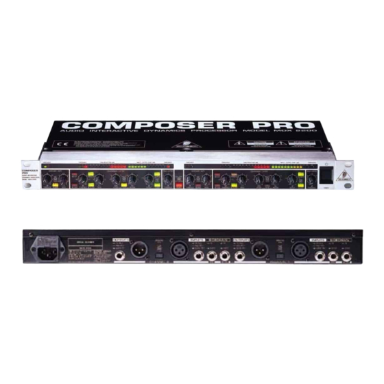
- Page 18 Fig. 4.5: Control elements of the rear panel...
-
Page 19: Applications
5. APPLICATIONS... - Page 20 Output Gain 0 dB Threshold IRC-Curve Expander, 1:8 Noise Gate, 1:oo Input Fig. 5.1: IRC curve characteristic of the Expander...
- Page 21 c t i Tab. 5.1: Initial settings for the expander/gate section...
- Page 22 Output Gain 0 dB Threshold Ratio 2:1 Hard Knee Ratio 4:1 Limiter oo:1 IKA Curve green yellow Input Fig. 5.2: IKA characteristic of the compressor section...
- Page 23 c t i c t i c t i c t i c t i c t i Tab. 5.2: Initial settings for the compressor section...
- Page 24 Peak Limiting Level Program Limiting Release Threshold Input Output 5 ms approx. 1 s 20 ms t/ms Fig. 5.3: IGC characteristic of the limiter section...
- Page 25 Tab. 5.3: Initial settings for the peak limiter section...
-
Page 26: Special Applications
6. SPECIAL APPLICATIONS... - Page 29 7. EXTERNAL SIDECHAIN APPLICATIONS...
- Page 30 c t i c t i c t i c t i : l o c t i Tab. 7.1: Initial settings for the De-Esser functions...
- Page 32 8. SPECIFICATIONS...
- Page 34 9. WARRANTY § 1 WARRANTY CARD § 2 WARRANTY § 3 RETURN AUTHORIZATION NUMBER BEHRINGER INTERNATIONAL GmbH Service Department § 5 WARRANTY TRANSFERABILITY Hanns-Martin-Schleyer-Str. 36-38 D - 47877 Willich-Münchheide § 4 WARRANTY REGULATIONS § 6 CLAIM FOR DAMAGES § 7 OTHER WARRANTY RIGHTS...