National Instruments NI-9213 Getting Started
Hide thumbs
Also See for NI-9213:
- Getting started manual (23 pages) ,
- Getting started (13 pages) ,
- Getting started (9 pages)
Table of Contents
Advertisement
Quick Links
Advertisement
Table of Contents

Related Manuals for National Instruments NI-9213


Summary of Contents for National Instruments NI-9213
- Page 1 NI-9213 Getting Started 2022-07-06...
-
Page 2: Table Of Contents
Safety Guidelines............3 NI-9213 (Black Connector) Safety Voltages....... . . 3 Safety Guidelines for Hazardous Voltages. -
Page 3: Overview
Note The guidelines in this document are specific to the NI-9213. The other components in the system might not meet the same safety ratings. Refer to the documentation for each component in the system to determine the safety and EMC ratings for the entire system. -
Page 4: Safety Guidelines For Hazardous Voltages
NI-9213 Getting Started Channel-to-channel None Channel-to-earth ground Continuous 250 V RMS, Measurement Category II Withstand 2,300 V RMS, verified by a 5 s dielectric withstand test Safety Guidelines for Hazardous Voltages If hazardous voltages are connected to the product, take the following precautions. -
Page 5: Safety Guidelines For Hazardous Locations
Safety Guidelines for Hazardous Locations The NI-9213 is suitable for use in Class I, Division 2, Groups A, B, C, D, T4 hazardous locations; Class I, Zone 2, AEx nA IIC T4 Gc and Ex nA IIC T4 Gc hazardous locations;... -
Page 6: Electromagnetic Compatibility Guidelines
NI-9213 Getting Started Capacitance 0.2 µF maximum Special Conditions for Hazardous Locations Use in Europe and Internationally The NI 9213 has been evaluated as Ex nA IIC T4 Gc equipment under DEMKO 07ATEX 0626664X and is IECEx UL 14.0089X certified. Each NI 9213 is marked II 3G and is suitable for use in Zone 2 hazardous locations, in ambient temperatures of -40 °C ≤... -
Page 7: Special Conditions For Marine Applications
Furthermore, any changes or modifications to the product not expressly approved by National Instruments could void your authority to operate it under your local regulatory rules. Special Conditions for Marine Applications Some products are approved for marine (shipboard) applications. -
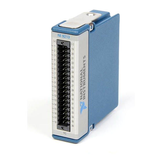
Page 8: Ni 9213 Pinout
NI-9213 Getting Started Note Refer to the device datasheet on ni.com/manuals for complete specifications. NI 9213 Pinout TC0+ TC0– TC0– TC0+ TC1+ TC1– TC1+ TC1– TC2+ TC2– TC2– TC2+ TC3+ TC3– TC3– TC3+ TC4+ TC4– TC4+ TC4– TC5+ TC5– TC5+ TC5–... -
Page 9: Connecting To A Spring-Terminal Connector
3. Remove the screwdriver from the activation slot to clamp the wire into place. High-Vibration Application Connections If your application is subject to high vibration, NI recommends that you use the NI-9940 backshell kit to protect connections to the NI-9213. © National Instruments... -
Page 10: Minimizing Thermal Gradients
Minimize adjacent heat sources and air flow across the terminals. ■ Keep the ambient temperature as stable as possible. ■ Make sure the NI-9213 terminals are facing forward or upward. ■ Keep the NI-9213 in a stable and consistent orientation. ■... -
Page 11: Where To Go Next
NI product. Product registration facilitates technical support and ensures that you receive important information updates from NI corporate headquarters is located at 11500 N Mopac Expwy, Austin, TX, 78759-3504, USA. © National Instruments © 2022 National Instruments Corporation.