Advertisement
Quick Links
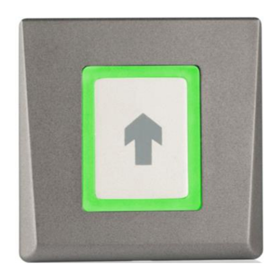
ACL870FL-PB - Flush Mount RTE Push Button -
Installation Manual
Description / Operation
ACL870FL-PB has a remote relay control unit for use with the
ACL870FL-BS and the ACL870SU-BS biometric readers. If a
secure installation is needed, the biometric reader can be
connected to this ACL870FL-PB at secured area. It also plays
the role of exit push button. It has two relay outputs and two
RTE button inputs.
The connection between the biometric reader and this
ACL870FL-PB unit is done via RS485. Once the reader and
the remote relay unit are paired, the reader will use the relays
of the ACL870FL-PB..
Specifications
Supply voltage
9 to 14 VDC
Current requirements
65 mA at 12 VDC
Relay output
2x relay - 2A at 24 VDC
Buzzer
Yes, on touch
Push button input:
2
Door time:
Pulse (1 to 60 sec) or Toggle (ON/OFF)
Tamper
Yes, activated on frame removal
© 2018 United Technologies Corporation.
Interlogix is part of UTC Climate, Controls & Security, a unit of United Technologies Corporation. All rights reserved.
Backlight ON/OFF
Yes, by DIP switch
Panel connection
Terminal block
Material of design
ABS
housing
Dimensions of housing
80 x 80 x 9 mm
(W x H x D)
Operating environment
−20 to +50°C
Temperature
0-95% noncondensing
Relative humidity
IP rating
IP40
-S = Silver, -G = Charcoal, -W = White
Color
140 g
Weight shipping
70 g
Weight product
Mounting
Figure 1:
Mounting instructions
P/N 1073517A• REV 01.01 • ISS 27AUG18
Advertisement

Summary of Contents for Interlogix ACL870FL-PB
- Page 1 Pulse (1 to 60 sec) or Toggle (ON/OFF) Tamper Yes, activated on frame removal P/N 1073517A• REV 01.01 • ISS 27AUG18 © 2018 United Technologies Corporation. Interlogix is part of UTC Climate, Controls & Security, a unit of United Technologies Corporation. All rights reserved.
- Page 2 Application Diagram Figure 2: Application diagram ACL870FL-PB 2 Relay remote unit and 2 request-to-exit button inputs Figure 3: Application Diagram P/N 1073517A• REV 01.01 • ISS 27AUG18 2 / 4...
- Page 3 Figure 4: Wiring instructions - Connect the door lock on the ACL870FL-PB relay - The reader and the remote relay unit ACL870FL-PB should be connected with 4 wires: +, -, A and B (RS485). Max. 50 m. Pairing reader with remote relay Figure 5: Wiring instructions 1.
- Page 4 RELATED PRODUCTS. For more information on warranty disclaimers and product safety information, please check www.firesecurityproducts.com/policy/product- warning/ or scan the following code: For contact information go to: www.interlogix.com Contact or www.firesecurityproducts.com information and To get translations for this and other product manuals manuals go to: www.firesecurityproducts.com...