Advertisement
Quick Links
USE AND CARE GUIDE
Questions, problems, missing parts?
Contact Husky's manufacturing partner for assistance:
7 a.m. - 5 p.m., CST, Monday-Friday:
Chat: www.edsal.com/chat or www.edsal.com/contact
Email: support@edsal.com
Phone: 1-773-475-3131
To obtain replacement parts please provide: Model Number, Part Number & Description, Store Location and Date Purchased
Important Safety Information
WARNING: Excessive weight hazard!
Do not leave children unattended near overhead rack. High risk of injury if installed incorrectly. Follow instructions
carefully and routinely inspect your system to ensure all components are fastened securely. DO NOT JUMP, CLIMB
OR HANG FROM THIS CEILING RACK. Never install more than one of these ceiling storage rack units on any two
overhead joist supports. Use care when working with metal parts, wear gloves. Do not use this unit for anything other
than the manufacture's intended purpose.
This unit has a total load capacity of 600 pounds of evenly
distributed weight (not to exceed 28 lbs. per square foot), using
all 8 lag bolts (included in package) anchored into solid wood
joists or supports capable of supporting such a load. Do not over
load. Do not attempt to mount to steel beams. Be sure overhead
joists and supports are structurally sound. Edsal is not liable for
structure failure, or damage or injury resulting from structure
failure.
Warranty
GUARANTEED FOREVER. If your Husky product ever fails bring it back and we will replace it for free. This full warranty gives you
specific rights which vary from state to state. If this product is defective contact the manufacturer for repair or replacement
parts.
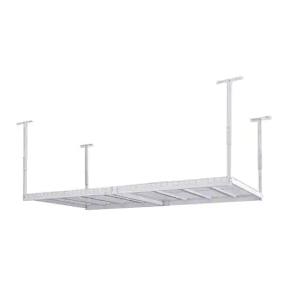
Adjustable Ceiling Storage Rack
Use two or more people to move and install this rack to avoid injury.
THANK YOU FOR YOUR PURCHASE
Model # ACR3296W
600 lbs.
Advertisement

Related Manuals for Husky ACR3296W


Summary of Contents for Husky ACR3296W
- Page 1 Warranty GUARANTEED FOREVER. If your Husky product ever fails bring it back and we will replace it for free. This full warranty gives you specific rights which vary from state to state. If this product is defective contact the manufacturer for repair or replacement parts.
-
Page 2: Parts List
Parts List Side Brace #GLSB-32 Left Beam #GLBML Right Beam Lower Post Ceiling Angle Upper Post #GLBMR Bracket #GLLR #GLUP #GLSA Cross Support Center Support #GLSTB-R-32 #GLFTB-32 End Wire Deck Center Wire Deck #GLWFDS-32 #GLWFD-32 Lag Bolt Hex Bolt Lock Nut Small Washer Large Washer Tools Required... - Page 3 Assembly Instructions Step 1 - Plan the Installation Determine if your ceiling rack will be installed parallel or perpendicular to the direction of your ceiling joists. Use a stud finder to locate the joists if ceiling is finished with drywall. Check the spacing of your ceiling joists to ensure that they will work for the size and direction of your ceiling rack install.
- Page 4 Assembly Instructions Step 2 - Install Ceiling Brackets (A) Locate and mark the center of ceiling joist with a pencil. Install Ceiling Angle Bracket (A) into marked joist using Use a stud finder to locate the joists if ceiling is finished two Lag Bolts (K) and two Large Washers (O) with a with drywall.
- Page 5 Assembly Instructions Step 3 - Assemble Upper and Lower Posts (B & C) Determine desired height of ceiling rack from the ceiling to bottom of the overhead rack. Join the upper and lower post and line up the holes to the determined height. Bolt Upper Post (B) to Lower Post (C) using two Hex Bolts (L), two Lock Nuts (M) and four Small Washers (N).
- Page 6 Assembly Instructions Step 4 - Install Post Assemblies Continued For Perpendicular Assembly: Bolt together one post assembly through the hole located on the side of the post to the center hole of the inside angle of bracket using one Hex Bolt (L), one Lock Nut (M) and two Small Washers (N). The backside of the post must be facing in and the tapered ends of the post slots must be facing down.
- Page 7 Assembly Instructions Step 6 - Assemble Left and Right Beams (E & F) Bolt together one Left Beam (E) and one Right Beam (F) at the determined 72” or 96” length assembly by using four Hex Bolts (L), four Lock Nuts (M) and eight Small Washers (N). Repeat steps to assemble the other Left and Right Beam.
- Page 8 Assembly Instructions Step 8 - Install Center Support (G) Bolt the Center Support (G) into the two holes found in the middle of each beam assembly (see diagrams for reference to hole location on a 72” or 96” beam assembly). Use two Hex Bolts (L), two Lock Nuts (M) and four Small Washers (N) per side.
- Page 9 Assembly Instructions Step 9 - Install Cross Supports (H) Assemble the six Cross Supports (H) by placing the rivets located on both ends of the cross support into the triangular holes located on the top ledge of both beam assemblies. ✓...
- Page 10 Assembly Instructions STEP 11 - Final Inspection Check each beam and post connection to be sure that the beams are properly seated and brackets are firmly connected to the overhead joists. Make sure all bolts and nuts are properly tightened. It is recommended to periodically repeat this inspection process to ensure safety.