
Related Manuals for Riello RS 810/M BLU


Summary of Contents for Riello RS 810/M BLU
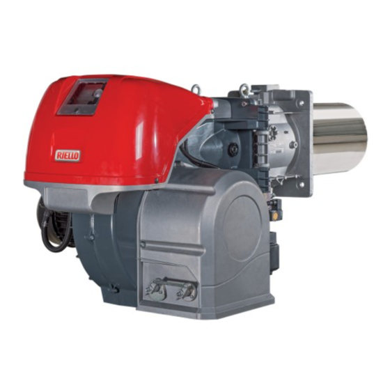
- Page 1 Installation, use and maintenance instructions Forced draught gas burner Modulating operation CODE MODEL TYPE 20155875 RS 810/M BLU S032T 20163413 (5) - 06/2021...
- Page 2 Translation of the original instructions...
-
Page 3: Table Of Contents
Contents Declarations....................................3 Information and general warnings............................4 Information about the instruction manual ........................4 2.1.1 Introduction.................................. 4 2.1.2 General dangers................................4 2.1.3 Other symbols ................................4 2.1.4 Delivery of the system and the instruction manual...................... 5 Guarantee and responsibility............................5 Safety and prevention................................ - Page 4 Contents Burner ignition ................................24 Servomotor adjustment ..............................24 Air / fuel adjustment ..............................24 6.6.1 Burner adjustment..............................25 6.6.2 Output upon ignition ..............................25 6.6.3 Maximum output ................................25 6.6.4 Minimum output .................................26 6.6.5 Intermediate outputs ..............................26 Pressure switch adjustment ............................27 6.7.1 Air pressure switch - check CO..........................27 6.7.2 Maximum gas pressure switch...........................27 6.7.3...
-
Page 5: Declarations
The quality is guaranteed by a quality and management system certified in accordance with ISO 9001:2015. Manufacturer's Declaration RIELLO S.p.A. declares that the following products comply with the NOx emission limits specified by German standard “1. BIm- SchV revision 26.01.2010”. -
Page 6: Information And General Warnings
Information and general warnings Information and general warnings Information about the instruction manual 2.1.1 Introduction WARNING: MOVING PARTS The instruction manual supplied with the burner: This symbol indicates that you must keep limbs is an integral and essential part of the product and must not away from moving mechanical parts;... -
Page 7: Delivery Of The System And The Instruction Manual
Information and general warnings 2.1.4 Delivery of the system and the instruction The system supplier must carefully inform the user about: – the use of the system; manual – any further tests that may be required before activating the When the system is delivered, it is important that: system;... -
Page 8: Safety And Prevention
Safety and prevention Safety and prevention Introduction The burners have been designed and built in compliance with the type and pressure of the fuel, the voltage and frequency of the current regulations and directives, applying the known technical electrical power supply, the minimum and maximum deliveries for rules of safety and envisaging all the potential danger situations. -
Page 9: Technical Description Of The Burner
3N / 400V / 50Hz 3/230/50 3 / 230V / 50Hz Voltage of auxiliaries: 230/50/60 230V / 50-60Hz 110/50/60 110V / 50-60Hz 3/400/50 230/50/60 BASIC DESIGNATION EXTENDED DESIGNATION Models available Designation Voltage Start-up Code RS 810/M BLU FS2 3/400/50 Star/Delta 20155875 Tab. A 20163413... -
Page 10: Burner Categories - Countries Of Destination
Gas category Destination country AT-BG-CH-CZ-DK-EE-ES-FI-GB-GR-HU-HR-IE-IS-IT-LT-LV-NO-PT- RO-SE-SI-SK-TR 2ELL 2E(R) LU - PL Tab. B Technical data Model RS 810/M BLU Power 1200/3500 ÷ 8010 Output Fuels Natural gas: G20 (methane gas) - G25 Gas pressure at max. output mbar 49.7/73 Gas: G20/G25... -
Page 11: Burner Equipment
Bear in mind that inspection of the combustion head requires the burner to be opened and the rear part turned on the hinge. The l position is reference for the refractory thickness of the boiler door. 20161935 Fig. 1 RS 810/M BLU 1197 DN80 1345 1055 Tab. E Burner equipment Thermal insulation screen . -
Page 12: Firing Rates
1013 mbar (approx. 0 m limit of the diagram: a.s.l.), and with the combustion head adjusted as WARNING shown on page 19. Model RS 810/M BLU 1200 20161991 Fig. 2 Thermal power – kW Test boiler The burner/boiler combination does not pose any problems if the... -
Page 13: Burner Description
Technical description of the burner 4.10 Burner description 20162042 Fig. 4 Lifting rings The burner can be opened to the right or to the left Cover for electrical panel without links to the fuel supply side. Lever for combustion head movement When the burner is closed, the hinge can be refit- Air pressure test point for combustion head CAUTION... -
Page 14: Electrical Panel Description
Technical description of the burner 4.11 Electrical panel description 20156529 Fig. 5 Ignition transformer 20156519 Burner state indicator light and reset button. For further information see section Burner ignition OFF-automatic-manual selector Electrical control box Power increase - power reduction selector Earth terminal Air pressure switch Bracket for applying the kits... -
Page 15: 4.12 Rfgo-A22 Control Box
The control box is a safety device! Avoid opening WARNING or modifying it, or forcing its operation. Riello S.p.A. cannot assume any responsibility for dam- age resulting from unauthorised interventions! All interventions (assembly and installation operations, assistance, etc.) must be carried out by qualified personnel. -
Page 16: 4.13 Servomotor Sqm41
Technical description of the burner 4.13 Servomotor SQM41 ... Warnings To avoid accidents, material or environmen- tal damage, observe the following instruc- tions! WARNING Avoid opening, modifying or forcing the ser- vomotor. All interventions (assembly and installation operations, assistance, etc.) must be carried out by qualified personnel. ... -
Page 17: 4.14 Calibration Of The Thermal Relay
Technical description of the burner 4.14 Calibration of the thermal relay The thermal relay serves to avoid damage to the motor due to an excessive absorption increase or if a phase is missing. For calibration 2), see the table in the wiring diagram. To reset, in case of an intervention of the thermal relay, press the “RESET”... -
Page 18: Installation
Installation Installation Notes on safety for the installation After carefully cleaning all around the area where the burner will The installation of the burner must be carried out be installed, and arranging the correct lighting of the environ- by qualified personnel, as indicated in this manual ment, proceed with the installation operations. -
Page 19: Operating Position
For boilers with front flue passes 1)(Fig. 15 on page 18) or flame inversion chamber, a protection in refractory material 5) must be RS 810/M BLU inserted between the boiler fettling 2) and the flame funnel 4). Tab. H This protection must not compromise the extraction of the blast tube. -
Page 20: Securing The Burner To The Boiler
Installation Securing the burner to the boiler 20162054 Prepare a suitable lifting system using rings 3)(Fig. 15). Fit the heat insulation supplied onto the blast tube 4)(Fig. 15). Fit the entire burner onto the boiler hole prepared previously (Fig. -
Page 21: Combustion Head Adjustment
Installation 5.10 Combustion head adjustment In order to optimise performance, the burner is equipped with a variable geometry combustion head which operates on the basis 20162133 of the delivered output. According to the same rotation of the air servomotor, it is possible to change the combustion head opening by moving the lever 2)(Fig. -
Page 22: Gas Feeding
Installation 5.11 Gas feeding Explosion danger due to fuel leaks in the pres- MBC “threaded” ence of a flammable source. Precautions: avoid knocking, attrition, sparks and heat. Make sure that the fuel interception tap is closed before performing any operation on the burner. The fuel supply line must be installed by qualified personnel, in compliance with current standards and laws. -
Page 23: 5.11.2 Gas Train
Installation 5.11.2 Gas train – subtract the combustion chamber pressure from the gas pressure measured at test point P1) (Fig. 24). Approved according to standard EN 676 and provided separately – Find, in the table Tab. J related to the burner concerned, the from the burner. -
Page 24: Electrical Wiring
Installation 5.12 Electrical wiring Notes on safety for the electrical wiring The electrical wiring must be carried out with the electrical supply disconnected. Electrical wiring must be made in accordance with the regulations currently in force in the country of destination and by qualified personnel. -
Page 25: Start-Up, Calibration And Operation Of The Burner
Start-up, calibration and operation of the burner Start-up, calibration and operation of the burner Notes on safety for the first start-up The first start-up of the burner must be carried out by qualified personnel, as indicated in this manual Before igniting the burner, see the paragraph and in compliance with the standards and regula- “Safety test - with gas feeding closed”... -
Page 26: Burner Ignition
Start-up, calibration and operation of the burner Burner ignition The burner should light after having performed the above steps. Motor lockout because of thermal relay intervention: because of an erroneous calibration of the thermal relay or If the motor starts up, but the flame does not appear and the con- problems with the motor or the main power supply. -
Page 27: Burner Adjustment
Start-up, calibration and operation of the burner 6.6.1 Burner adjustment Air adjustment The air is adjusted by varying the angle of cam I) (Fig. 27 on The optimum adjustment of the burner requires an analysis of page 23) and by using the selector 2)(Fig. 27 on page 23). To ad- flue gases at the boiler outlet. -
Page 28: Minimum Output
Start-up, calibration and operation of the burner 6.6.4 Minimum output 6.6.5 Intermediate outputs Min output must be selected within the firing rate range shown on Air adjustment Fig. 2 on page 10. No adjustment is required Press button 2)(Fig. 27 on page 23) “Diminishing output” and keep it pressed until the servomotor regains (Fig. -
Page 29: Pressure Switch Adjustment
CO in the fumes exceeds On RS 810/M BLU burners the air pressure switch is fitted in an “absolute” mode, that is, connected only to the pressure test point “+”... -
Page 30: Operation Sequence Of The Burner
Start-up, calibration and operation of the burner Operation sequence of the burner 6.8.1 Burner start-up 6.8.4 Burner flame goes out during operation If the flame should go out during operation, the burner will lockout within 1s. TL thermostat/pressure switch closure. Normal ignition Fan motor start. -
Page 31: Maintenance
Maintenance Maintenance Notes on safety for the maintenance The periodic maintenance is essential for the good operation, Before carrying out any maintenance, cleaning or checking oper- safety, yield and duration of the burner. ations: It allows you to reduce consumption and polluting emissions and to keep the product in a reliable state over time. -
Page 32: Safety Components
Flame presence check Air excess Check the level of the flame detection signal with the “Check EN 676 Max. output Min. output mode” function from the flame control: the LEDs from 2 to 6 1.2 1.3 indicate the flame signal level, respectively. See “LED indicator % Calibration theoretic and special function”... -
Page 33: Led Indicator And Special Function
LED indicator and special function Description of LED lamps It turns on when the fan motor is powered (T6) and blinks when RUN/CHECK switch is set to “CHECK” during damper movement phases, PTFI AND MTFI. S9740 It blinks when the air damper is moving towards the maximum opening position until the Open position-reached feedback sent by the servomotor is received, then it stays steadily on for the damper... -
Page 34: Led Lamps: Burner Operating Status
LED lamps: burner operating status OPERATING STATUSES INDICATED BY LEDS DURING NORMAL OPERATION AND CHECK MODE Operation Open Closed Modulation Ignition Flame Status LED ● = ON damper damper Icon S9740 S9741 S9742 S9743 S9744 S9745 S9746 Power OFF/ON Not ready/ Green Diagnostics Standby... -
Page 35: Problems - Causes - Remedies Signalled By Led Indicators
Problems - Causes - Remedies signalled by LED indicators Problems - Causes - Remedies signalled by LED indicators When an emergency stop occurs, the control device LEDs Thermal unit’s operation, maintenance and indicate the cause of the stop. troubleshooting interventions must be carried out The terminal T3 is not powered. - Page 36 Problems - Causes - Remedies signalled by LED indicators Error / RFGO LED lock-out codes Faults LED 1 LED 2 LED 3 LED 4 LED 5 LED 6 LED 7 Operation Open Closed Auto Ignition Flame Status LED ● = ON damper damper Icon...
- Page 37 Problems - Causes - Remedies signalled by LED indicators Faults LED 1 LED 2 LED 3 LED 4 LED 5 LED 6 LED 7 Off-specification mains voltage ● ● ● ● ● UV: Internal fault ● ● Supervisor processor fault ●...
- Page 38 Problems - Causes - Remedies signalled by LED indicators Fault explanation Faults Cause Solution Post-diagnostics fault Initial power diagnostics fault Make sure that the status of inlets and Check T12, T13 and T14 outlets is correct upon ignition Local reset The user started the manual reset or the Check T21 inlet or reset for normal reset switch is faulty...
- Page 39 Problems - Causes - Remedies signalled by LED indicators Faults Cause Solution Not used Internal processor timeout Internal fault Replace the control device Internal processor timeout Internal fault Replace the control device Combustion air check timeout The system could not perform verification tests of the combustion air during the burner Check the wiring or the air pressure switch sequence...
-
Page 40: A Appendix - Accessories
Appendix - Accessories Appendix - Accessories Analogue control signal converter kit Burner Type Code 0/2 - 10V RS 810/M BLU 20074479 0/4 - 20mA Kit for modulating operation Burner Output regulator Code RWF 50.2 3-POINT OUTLET 20073595 RS 810/M BLU RWF 55.5 COMPLETE WITH RS-485 INTERFACE... -
Page 41: B Appendix - Electrical Panel Layout
Appendix - Electrical panel layout Appendix - Electrical panel layout Index of layouts Indication of references Single-wire output layout Functional layout Functional layout RFGO Functional layout gas train Functional layout RFGO RWF50 kit electrical wiring... internal Electrical wiring that the installer is responsible for Electrical wiring that the installer is responsible for RWF50 kit electrical wiring... - Page 42 Appendix - Electrical panel layout 20163413...
- Page 43 Appendix - Electrical panel layout & & 20163413...
- Page 44 Appendix - Electrical panel layout 20163413...
- Page 45 Appendix - Electrical panel layout 20163413...
- Page 46 Appendix - Electrical panel layout 20163413...
- Page 47 Appendix - Electrical panel layout 20163413...
- Page 48 Appendix - Electrical panel layout 20163413...
- Page 49 Appendix - Electrical panel layout 20163413...
- Page 50 Appendix - Electrical panel layout 20163413...
- Page 51 Appendix - Electrical panel layout Wiring layout key Electrical control box Output power regulator RWF40 internal Input in current DC 0...20 mA, 4...20 mA Input in current DC 0...20 mA, 4...20 mA to modify re- mote setpoint Pressure probe Pressure probe Remote setpoint potentiometer Thermocouple probe Probe Pt100, 2 wires...
- Page 52 RIELLO S.p.A. I-37045 Legnago (VR) Tel: +39.0442.630111 http:// www.riello.it http:// www.riello.com Subject to modifications...