Table of Contents
Advertisement
Quick Links
Federal Communications Commission
(F.C.C) Statement
This device complies with Part 15 of the FCC Rules. Operation of this
device is subject to the following two conditions: (1) this device may not
cause harmful interference, and (2) this device must accept any
interference received, including interference that may cause undesired
operation.
Accessories: This device has been tested and found to comply with the
limits of a Class B digital device, the accessories associated with this
equipment are as follows:
1. Shielded serial cable. (Can be obtained from multiple retail outlets)
2. Shielded printer cable. (Can be obtained from multiple retail outlets)
3. Shielded video cable. (Can be obtained from multiple retail outlets)
4. Shielded power cord. (Provided by manufacturer)
These accessories are required to ensure compliance with FCC Rules. It
is the responsibility of the user to provide and use these accessories
properly.
This equipment has been tested and found to comply with the limits of a
Class B digital device, pursuant to Part 15 of the FCC Rules. These limits
are designed to provide reasonable protection against harmful
interference in a residential installation. This equipment generates, uses
and can radiate radio frequency energy and, if not installed and used in
accordance with the instructions, may cause harmful interference to radio
communications. There is no guarantee that interference will not occur in
a particular installation. If this equipment does cause harmful interference
to radio or television reception, which can be determined by turning the
equipment off and on, you are encouraged to try to correct the
interference by one or more of the following measures:
1. Reorient / relocate the receiving antenna.
2. Increase the separation between the equipment and receiver.
3. Connect the equipment into an outlet on a circuit different from that
to which the receiver is connected.
4. Consult the dealer or an experienced radio/TV technician for help.
Caution: Changes or modifications not expressly approved by the
Advertisement
Table of Contents

Related Manuals for Biostar BVK2A


Summary of Contents for Biostar BVK2A
- Page 1 Federal Communications Commission (F.C.C) Statement This device complies with Part 15 of the FCC Rules. Operation of this device is subject to the following two conditions: (1) this device may not cause harmful interference, and (2) this device must accept any interference received, including interference that may cause undesired operation.
- Page 2 manufacturer could void the user’s authority to operate the equipment. Disclaimer The vendor makes no representations or warranties with respect to the contents here of and specially disclaims any implied warranties of merchantability or fitness for any purpose. Further the vendor reserves the right to revise this publication and to make changes to the contents here of without obligation to notify any party beforehand.
-
Page 3: Table Of Contents
Contents Introduction.................1-1 1 Motherboard Description............1-2 1.1 Features....................1-2 1.1.1 Hardware..................1-2 1.1.2 Software...................1-4 1.1.3 Attachments..................1-4 1.2 Motherboard Installation.................1-5 1.2.1 Layout of Motherboard..............1-5 1.3 Motherboard Connectors.................1-6 1.3.1 Front Panel Connectors (JPANEL1 / JP5)........1-7 1.3.2 Floppy Disk Connector (FDD1)............1-9 1.3.3 Hard Disk Connectors (IDE1/IDE2)..........1-9 1.3.4 ATX 20-pin Power Connector (JATXPWR1).......1-11 1.4 Back Panel Connectors................1-12 1.4.1 PS/2 Mouse / Keyboard CONN.: JKBMS1........1-12... - Page 4 Contents 1.7.2 System Fan Connector: JSFAN1...........1-23 1.7.3 Wake-On MODEM Header: JWOM1(Optional)......1-23 1.7.4 Wake-On-LAN Header: JWOL1...........1-23 1.7.5 AMR Code Primary/Secondary Selection: J4.......1-23 1.7.6 CMOS Function Selection: JCMOS1..........1-24 1.8 DRAM Installation................1-25 1.8.1 DIMM....................1-25 1.8.2 How to install a DIMM Module............1-27 1.9 Audio Subsystem...................1-28 1.9.1 CD Audio-In Connectors: JCDIN1/JCDIN2.........1-29 1.9.2 Telephony Connector: JTAD1............1-29 1.9.3 AUX Audio in Connector: JAUX1 (Optional)......1-29...
- Page 5 Contents 2.10 Load Fail-Safe Defaults...............2-36 2.11 Load Optimized Defaults..............2-37 2.12 Set Supervisor / User Password............2-38 2.13 Save & Exit Setup................2-40 2.14 Exit Without Saving................2-41 3. Software Setup.................3-1 3.1 Software List....................3-1 3.2 Software Installation................3-2 3.3 Using Software..................3-3 4. Trouble shooting...............4-1...
-
Page 6: Introduction
Chapter 1 Motherboard Description Introduction System Overview Thanks for buying this product! This manual was written to help you start using this product as quickly and smoothly as possible. Inside you will find adequate explanations to solve most problems. In order for this reference material to be of greatest use, refer to the “expanded table of contents”... -
Page 7: Motherboard Description
Chapter 1 Motherboard Description 1 Motherboard Description 1.1 Features 1.1.1 Hardware Single AMD Socket-A for Athlon (Thunderbird ) / Duron processor Module-500MHz and faster. 200MHz System Interface speed. Speed Support 33MHz PCI Bus speed. Support 4X AGP Bus. DRAM Memory ... - Page 8 Chapter 1 Motherboard Description Flash Memory Support flash memory. Support ESCD Function. IDE Built-in On Board Supports four IDE hard disk drives. Supports PIO Mode 4, Master Mode, high performance hard disk drives. Support Ultra DMA 33, 66 Bus Master Mode. ...
-
Page 9: Software
Chapter 1 Motherboard Description Universal Serial Bus Supports two back Universal Serial Bus (U.S.B.) Ports and two front Universal serial Bus (U.S.B) Ports (Optional). Supports 48 MHz USB. Hardware Monitor Function CPU Fan Speed Monitor. System (Optional) and CPU Temperature Monitor. ... -
Page 10: Motherboard Installation
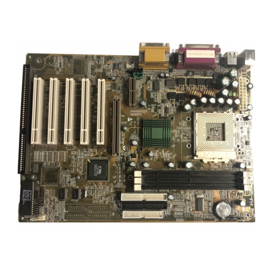
Chapter 1 Motherboard Description 1.2 Motherboard Installation 1.2.1 Layout of Motherboard Model No.BVK2A... -
Page 11: Motherboard Connectors
Chapter 1 Motherboard Description 1.3 Motherboard Connectors A. Back Panel I/O Connectors L. Front Two USB Connector (*JUSB2) B. CD Audio-In Connector (JCDIN1/2) M. Front Panel Connector (PANEL1) C. AMR CODEC Primary/Secondary N. AGP BUS Slot (AGP1) Selection (J4) O. IDE Connectors (IDE1/2) D. -
Page 12: Front Panel Connectors (Jpanel1 / Jp5)
Chapter 1 Motherboard Description 1.3.1 Front Panel Connectors (JPANEL1 / JP5) Assignment Function No Connection (Speaker No Connection Connector) Speaker JPANEL1 Pin Assignment Function Assignment Function HDD LED (+) Hard Drive Power LED (-) Power HDD LED (-) Power LED (+) Ground Reset Power Button... - Page 13 Chapter 1 Motherboard Description Ir-Out Speaker Connector An offboard speaker can be installed on the motherboard as a manufacturing option. An offboard speaker can be connected to the motherboard at the front panel connector. The speaker (onboard or offboard) provides error beep code information during the Power On Self-Test when the computer cannot use the video interface.
-
Page 14: Floppy Disk Connector (Fdd1)
Chapter 1 Motherboard Description Closing the SMI switch sends a System Management Interrupt (SMI) to the processor, which immediately goes into System Management Mode (SMM).While the computer is in sleep mode it is fully capable of responding to and servicing external interrupts (such as an incoming fax) even though the monitor turns on only if a keyboard or mouse interrupt occurs. -
Page 15: Atx 20-Pin Power Connector (Jatxpwr1)
Chapter 1 Motherboard Description 1.3.4 ATX 20-pin Power Connector (JATXPWR1) This connector supports the power button on-board. Using the ATX power supply, functions such as Modem Ring Wake-Up and Soft Power Off are supported on this motherboard. This power connector supports instant power-on functionality, which means that the system will boot up instantly when the power connector is inserted on the board. -
Page 16: Back Panel Connectors
Chapter 1 Motherboard Description 1.4 Back Panel Connectors 1.4.1 PS/2 Mouse / Keyboard CONN.: JKBMS1 The motherboard provides a standard PS/2 mouse / Keyboard mini DIN connector for attaching a PS/2 mouse. You can plug a PS/2 mouse / Keyboard directly into this connector. -
Page 17: Usb Connectors: Jusb1
Chapter 1 Motherboard Description PS/2 Mouse / Keyboard Connectors Signal Name Data No connect Ground +5 V (fused) Clock No connect 1.4.2 USB Connectors: JUSB1 The motherboard provides a OHCI (Open Host Controller Interface) Universal Serial Bus Roots for attaching USB devices such as: keyboard, mouse and other USB devices. - Page 18 Chapter 1 Motherboard Description 1-13...
- Page 19 Chapter 1 Motherboard Description Signal Name Signal Name Ground USBP2- Ground USBP2+ USBP3+ Ground USBP3- Ground 1-14...
-
Page 20: Serial And Parallel Interface Ports
Chapter 1 Motherboard Description 1.5 Serial and Parallel Interface Ports This system comes equipped with two serial ports and one parallel port. Both types of interface ports will be explained in this chapter. The Serial Interface: COM1/COM2 The serial interface port is sometimes referred to as an RS-232 port or an asynchronous communication port. - Page 21 Chapter 1 Motherboard Description Connectivity The serial ports can be used in many ways, and it may be necessary to become familiar with the pinout diagram. The following chart gives you the function of each pin on the 9-pin connector and some of the 25-pin connector. This information can be used when configuring certain software programs to work with the serial ports.
- Page 22 Chapter 1 Motherboard Description Parallel Interface Ports Unlike the serial ports, parallel interface port has been standardized and should not present any difficulty interfacing peripherals to your system. Sometimes called Centronics port, the parallel port is almost exclusively used with printers. The parallel port on your system has a 25-pin, DB25 connector (see picture below).
-
Page 23: Cpu Installation
Chapter 1 Motherboard Description 1.6 CPU Installation 1.6.1 CPU Installation Procedure: Socket A Pull the lever sideways away from the socket then raise the lever up to a 90-degree angle. Locate Pin A in the socket and look for the white dot or cut edge in the CPU. -
Page 24: Cpu Clock Selection: Jclk1
Chapter 1 Motherboard Description 1.6.2 CPU Clock Selection: JCLK1 1-19... -
Page 25: Jumper Settings
Chapter 1 Motherboard Description CPU Clock 100.0MHz 33.3MHz 102.0MHz 34.0MHz 104.0MHz 34.6MHz 106.0MHz 35.3MHz 107.0MHz 35.6MHz 108.0MHz 36.0MHz 109.0MHz 36.3MHz 110.0MHz 36.6MHz 111.0MHz 37.0MHz 112.0MHz 37.3MHz 133.3MHz 33.3MHz NOTES: CPU clock speed over 100MHz is not recommended. 1.7 Jumper Settings A jumper has two or more pins that can be covered by a plastic jumper cap, allowing you to select different system options. - Page 26 Chapter 1 Motherboard Description 1-21...
-
Page 27: Cpu Fan Connector: Jcfan1
Chapter 1 Motherboard Description 1.7.1 CPU Fan Connector: JCFAN1 Pin No. Assignment Ground +12V Sense 1-22... -
Page 28: System Fan Connector: Jsfan1
Chapter 1 Motherboard Description 1.7.2 System Fan Connector: JSFAN1 Pin No. Assignment Ground +12V Sense 1.7.3 Wake-On MODEM Header: JWOM1(Optional) Pin No. Assignment 5V SB Ground Wake Up 1.7.4 Wake-On-LAN Header: JWOL1 Pin No. Assignment 5V SB Ground Wake up 1.7.5 AMR Code Primary/Secondary Selection: J4 Pin No. -
Page 29: Cmos Function Selection: Jcmos1
Chapter 1 Motherboard Description 1.7.6 CMOS Function Selection: JCMOS1 JCMOS1 Assignment Normal Operation (default) 1-2 Closed Clear CMOS Data 2-3 Closed Note: Please follow the procedure as below to clear CMOS data. Note: Please follow the procedure as below to clear BIOS password if your password is lost or forgotten. -
Page 30: Dram Installation
Chapter 1 Motherboard Description 1.8 DRAM Installation 1.8.1 DIMM DRAM Access Time : 3.3V Unbuffered SDRAM PC66/ PC100 and PC133 Type required. DRAM Type : 8MB/ 16MB/ 32MB/ 64MB/ 128MB/ 256MB DIMM Module (168pin) Total Bank 0 Bank 1 Bank 2 Memory Size (MB) DIMM1 DIMM2... - Page 31 Chapter 1 Motherboard Description Total Bank 0 Bank 1 Bank 2 Memory Size (MB) DIMM1 DIMM2 DIMM3 48 M 8M x 1 pc 8M x 1 pc 32M x 1 pc 64 M 16M x 1 pc 16M x 1 pc 32M x 1 pc 96 M 32M x 1 pc...
-
Page 32: How To Install A Dimm Module
Chapter 1 Motherboard Description 1.8.2 How to install a DIMM Module 1. The DIMM socket has a “ Plastic Safety Tab” and the DIMM memory module has an asymmetrical notch”, so the DIMM memory module can only fit into the slot in one direction. -
Page 33: Audio Subsystem
Chapter 1 Motherboard Description 1.9 Audio Subsystem 1-28... -
Page 34: Cd Audio-In Connectors: Jcdin1/Jcdin2
Chapter 1 Motherboard Description 1.9.1 CD Audio-In Connectors: JCDIN1/JCDIN2 Pin No. of JCDIN2 Assignment Right Channel Input Ground Left Channel Input Ground Pin No. of JCDIN1 Assignment Right Channel Input Ground Ground Left Channel Input 1.9.2 Telephony Connector: JTAD1 Pin No. MONO_IN Ground Ground... -
Page 35: Front Audio Connector: Jf_Audio (Optional)
Chapter 1 Motherboard Description 1.9.4 Front Audio Connector: JF_AUDIO (Optional) Signal Name Signal Name Line_out_L Line_out_R GROUND Ground Line_in_L Line_in_R GROUND Pin Removed as key pin MIC_in Ground 1-30... -
Page 36: Bios Setup
Chapter2 BIOS Setup 2. BIOS Setup Introduction This manual discussed Award™ Setup program built into the ROM BIOS. The Setup program allows users to modify the basic system configuration. This special information is then stored in battery-backed RAM so that it retains the Setup information when the power is turned off. - Page 37 Chapter2 BIOS Setup PCI Bus Support This AWARD BIOS also supports Version 2.1 of the Intel PCI (Peripheral Component Interconnect) local bus specification. DRAM Support SDRAM (Synchronous DRAM) are supported. Supported CPUs This AWARD BIOS supports the AMD Athlon / Duron CPU.
-
Page 38: Main Menu
Chapter2 BIOS Setup 2.1 Main Menu Once you enter Award BIOS™ CMOS Setup Utility, the Main Menu will appear on the screen. The Main Menu allows you to select from several setup functions. Use the arrow keys to select among the items and press <Enter> to accept and enter the sub-menu. - Page 39 Chapter2 BIOS Setup Integrated Peripherals This section page includes all the items of IDE hard drive and Programmed Input/ Output features. Power Management Setup This setup page includes all the items of power management features. PnP/PCI Configurations This setup page includes IRQ Setting by user define or default. PC Health Status This page shows the hardware Monitor information of the system.
-
Page 40: Standard Cmos Features
Chapter2 BIOS Setup 2.2 Standard CMOS Features The items in Standard CMOS Setup Menu are divided into 10 categories. Each category includes no, one or more than one setup items. Use the arrow keys to highlight the item and then use the<PgUp> or <PgDn> keys to select the value you want in each item. - Page 41 Chapter2 BIOS Setup Main Menu Selections This table shows the selections that you can make on the Main Menu. Item Options Description Date Month DD YYYY Set the system date. Note that the ‘Day’ automatically changes when you set the date.
- Page 42 Chapter2 BIOS Setup Item Options Description Halt On All Errors Select the situation in which No Errors you want the BIOS to stop All, but Keyboard the POST process and All, but Diskette notify you. All, but Disk/ Key Base Memory Displays the amount of conventional memory detected during boot up.
-
Page 43: Advanced Bios Features
Chapter2 BIOS Setup 2.3 Advanced BIOS Features Figure 3. Advanced BIOS Setup CMOS Setup Utility-Copyright (C ) 1984-2000 Award Software Advanced BIOS Features Anti-Virus Protection Enabled Item Help CPU Internal Cache Enabled External Cache Menu Level Enabled CPU L2 Cache ECC Checking Enabled Quick Power On Self Test Enabled... - Page 44 Chapter2 BIOS Setup CPU Internal Cache These two categories speed up memory access. However, it depends on CPU/chipset design. Enabled (default) Enable cache. Disabled Disable cache. External Cache These fields allow you to Enable or Disable the CPU’s “Level 2” secondary cache.
- Page 45 Chapter2 BIOS Setup Boot Up Floppy Seek Seeks disk drives during boot up. Disabling speeds boot-up. The Choices: Enabled (default), Disabled. Boot Up NumLock Status Select power on state for NumLock. On (default) Numpad is number keys. Numpad is arrow keys. Gate A20 Option Select if chipset or keyboard controller should control Gate A20.
- Page 46 Chapter2 BIOS Setup C8000 - CFFFF Shadow / D0000 - DFFFF Shadow Determines whether the optional ROM will be copied to RAM for faster execution. Enabled Optional ROM is shadowed. Disabled (default) Optional ROM is not shadowed. Note : For C8000 - DFFFF option - ROM on PCI BIOS, BIOS will automatically enable the shadow RAM.
-
Page 47: Advanced Chipset Features
Chapter2 BIOS Setup 2.4 Advanced Chipset Features This section allows you to configure the system based on the specific features of the installed chipset. This chipset manages bus speeds and access to system memory resources, such as DRAM and the external cache. It also coordinates communications the PCI bus. It must be stated that these items should never need to be altered. - Page 48 Chapter2 BIOS Setup OnChip Modem This item allows you to control the onboard MC97 Modem controller. The choices: Auto (default), Disabled. OnChip USB/USB2 This should be enabled if your system has a USB installed on the system board and you wish to use it. Even when so equipped, if you add a higher performance controller, you will need to disable this feature.
- Page 49 Chapter2 BIOS Setup AGP Driving Value While AGP driving control item set to "Manual", it allows user to set AGP driving. AGP Master 1 WS Write When Enabled, writes to the AGP(Accelerated Graphics Port) are executed with one wait states. The choices: Disabled (default), Enabled.
- Page 50 Chapter2 BIOS Setup Fast R-W Turn Around This item controls the DRAM timing. It allows you to enable/disable the fast read/write turn around. The Choices: Disabled (default), Enabled. Video RAM Cacheable Select Enabled allows caching of the video BIOS, resulting in better system performance.
-
Page 51: Integrated Peripherals
Chapter2 BIOS Setup 2.5 Integrated Peripherals Figure 5. Integrated Peripherals CMOS Setup Utility-Copyright (C ) 1984-2000 Award Software Integrated Peripherals OnChip IDE Control Press Enter Item Help Muti-Media setting Press Enter Init Display First PCI Slot Menu Level Onboard FDD Controller Enabled Onboard Serial Port 1 3F8/IRQ4... - Page 52 Chapter2 BIOS Setup The Choices: Enabled (default), Disabled. OnChip IDE Channel 0 The chipset contains a PCI IDE interface with support for two IDE channels. Select Enabled to activate the secondary IDE interface. Select Disabled to deactivate this interface. The Choices: Enabled (default), Disabled. IDE Prefetch Mode The onboard IDE drive interfaces supports IDE prefetching, for faster drive access.
- Page 53 Chapter2 BIOS Setup support. The Choices: Enabled (default), Disabled. Muti-Media setting The multimedia setting submenu is used to configure various multimedia peripherals such as audio and game equipment. If you highlight the literal “Press Enter” next to the “Muti-Media setting” label and then press the enter key, it will take you a submenu with the following options: Onboard Legacy Audio Select an operating mode for the second serial port:...
- Page 54 Chapter2 BIOS Setup This item allows you decide to active whether PCI Slot or AGP Slot. The Choices: PCI Slot (default), AGP. 2-19...
- Page 55 Chapter2 BIOS Setup Onboard FDD Controller Select Enabled if your system has a floppy disk controller (FDC) installed on the system board and if you wish to use it. If install and FDC or the system has no floppy drive, select Disabled in this field. The Choices: Enabled (default), Disabled.
- Page 56 Chapter2 BIOS Setup ECP Mode Use DMA Select a DMA channel for the parallel port for use during ECP mode. The Choice: 3 . Parallel Port EPP Type Select a DMA Channel for the port. The Choice: EPP1.9. 2-21...
-
Page 57: Power Management Setup
Chapter2 BIOS Setup 2.6 Power Management Setup The Power Management Setup allows you to configure your system to most effectively save energy while operating in a manner consistent with your own style of computer use. Figure 6. Power Management Setup ... - Page 58 Chapter2 BIOS Setup Doze Mode. Suspend Mode. If you highlight the literal “Press Enter” next to the “Power Management” label and then press the enter key, it will take you a submenu with the following options: Power Management This option allows you to set each mode individually. When not disabled, each of the ranges are from 1 min.
- Page 59 Chapter2 BIOS Setup Video Off Option This field determines when to activate the video off feature for monitor power management. Video Off Method This determines the manner in which the monitor is blanked. V/H SYNC+Blank This selection will cause the system to turn (default) off the vertical and horizontal synchronization ports and write blanks to...
- Page 60 Chapter2 BIOS Setup always set CMOS in "Off" status when AC power lost; failed. For example: BIOS setup to "Formor-Sts". If AC power lost when system in power on "status, then after AC power retrieved, system will automatic power on. If AC power lost when system in "power off"...
- Page 61 Chapter2 BIOS Setup RTC Alarm Resume When “Enabled”, you can set the date and time at which the RTC (real-time clock) alarm awakens the system from Suspend mode. Primary INTR When set to ON (default), any event occurring at Primary INTR will awaken a system which has been powered down.
-
Page 62: Pnp/Pci Configurations
Chapter2 BIOS Setup 2.7 PnP/PCI Configurations This section describes configuring the PCI bus system. PCI, or Personal Computer Interconnect, is a system which allows I/O devices to operate at speeds nearing the speed of the CPU itself uses when communicating with its own special components. - Page 63 Chapter2 BIOS Setup Reset Configuration Data The system BIOS supports the PnP feature so the system needs to record which resource is assigned and proceeds resources from conflict. Every peripheral device has a node, which is called ESCD. This node records which resources are assigned to it.
- Page 64 Chapter2 BIOS Setup IRQ Resources When resources are controlled manually, assign each system interrupt a type, depending on the type of device using the interrupt. DMA Resources When resources are controlled manually, assign each system DMA channel a type, depending on the type of device using the DMA channel. PCI / VGA Palette Snoop Choose Disabled or Enabled.
-
Page 65: Pc Health Status
Chapter2 BIOS Setup 2.8 PC Health Status Figure 8. PC Health Status CMOS Setup Utility-Copyright (C ) 1984-2000 Award Software PC Health Status Show H/W Monitor in POST 3 sec Item Help Current CPU Temp. Current System Temp. Menu Level Current CPUFAN Speed Current SYS.FAN Speed Vcore... - Page 66 Chapter2 BIOS Setup Current CPUFAN Speed These fields display the current speed of up to CPU fans, if your computer contains a monitoring system. Current SYS.FAN Speed These fields display the current speed of up to three system fans, if your computer contains a monitoring system.
-
Page 67: Frequency / Clock Control
Chapter2 BIOS Setup 2.9 Frequency / Clock Control Figure 9. Frequency / Clock Control CMOS Setup Utility-Copyright (C ) 1984-2000 Award Software Frequency / Clock Control Auto Detect DIMM / PCI CLK Enabled Item Help CPU Host/PCI/Spread Spec. Default Menu Level : Move Enter :Select +/-/PU/PD :Value F10 :Save ESC :Exit F1 :General Help F5 :Previous Values... -
Page 68: Load Fail-Safe Defaults
Chapter2 BIOS Setup 2.10 Load Fail-Safe Defaults When you press <Enter> on this item, you get a confirmation dialog box with a message similar to: Figure 10. Load Fail-Safe Defaults CMOS Setup Utility-Copyright (C ) 1984-2000 Award Software Standard CMOS Features Frequency / Clock Control Advanced BIOS Features Load Fail-Safe Defaults... -
Page 69: Load Optimized Defaults
Chapter2 BIOS Setup 2.11 Load Optimized Defaults When you press <Enter> on this item, you get a confirmation dialog box with a message similar to: Figure 11. Load Optimized Defaults CMOS Setup Utility-Copyright (C ) 1984-2000 Award Software Standard CMOS Features Frequency / Clock Control Advanced BIOS Features Load Fail-Safe Defaults... -
Page 70: Set Supervisor / User Password
Chapter2 BIOS Setup 2.12 Set Supervisor / User Password Figure 12. Set Supervisor / User Password CMOS Setup Utility-Copyright (C ) 1984-2000 Award Software Standard CMOS Features Frequency / Clock Control Advanced BIOS Features Load Fail-Safe Defaults Advanced Chipset Features Load Optimized Defaults Integrated Peripherals Set Supervisor Password... - Page 71 Chapter2 BIOS Setup PASSWORD DISABLED If you select “System” at the Security Option of BIOS Features Setup Menu, you will be prompted for the password every time when the system is rebooted, or any time when you try to enter Setup. If you select “Setup” at Security Option of BIOS Feature Setup Menu, you will be prompted only when you try to enter Setup.
-
Page 72: Save & Exit Setup
Chapter2 BIOS Setup 2.13 Save & Exit Setup Figure 13. Save & Exit Setup CMOS Setup Utility-Copyright (C ) 1984-2000 Award Software Standard CMOS Features Frequency / Clock Control Advanced BIOS Features Load Fail-Safe Defaults Advanced Chipset Features Load Optimized Defaults Integrated Peripherals Set Supervisor Password SAVE to CMOS and EXIT (Y/N)? Y... -
Page 73: Exit Without Saving
Chapter2 BIOS Setup 2.14 Exit Without Saving Figure 14. Exit Without Saving CMOS Setup Utility-Copyright (C ) 1984-2000 Award Software Standard CMOS Features Frequency / Clock Control Advanced BIOS Features Load Fail-Safe Defaults Advanced Chipset Features Load Optimized Defaults Quit without Saving (Y/N)? N Integrated Peripherals Set Supervisor Password... -
Page 74: Software Setup
Chapter 3 Software Setup 3. Software Setup NOTE: The mark * means it can be installed directly from CD by using CD Installation Utility ( i.e. START.EXE). 3.1 Software List Category Description Platform Location in CD VIA 4 In 1 driver includes (VIA VIA Service Pack Windows 95 / \Mb_drv\... -
Page 75: Software Installation
Chapter 3 Software Setup 3.2 Software Installation We provide an installation wizard, Driver CD Installation Utility (START.EXE), located in the root of Driver CD to let users install some common used drivers conveniently. The drivers can be installed from CD by using CD Installation Utility: You can simply put Driver CD into CD-ROM drive and the Installation Utility will autorun or you can run the Driver CD Installation Utility directly by using... -
Page 76: Using Software
Chapter 3 Software Setup 3.3 Using Software In general, you can get more detailed information in the on-line help or readme for the softwares. Using VIA Hardware Monitor After the utility is installed, you can follow the sequence, Start Program →... - Page 77 Chapter 3 Software Setup The following figure is the main panel of VIA Hardware Monitor. In the panel, you can get some real-time and important information -- Voltage, Fan speed, and temperature, for example. If there is an abnormal situation, you can resolve it immediately.
-
Page 78: Trouble Shooting
Chapter 4 Trouble shooting 4. Trouble shooting PROBLEM No power to the system at all. Power light does not illuminate, fan inside power supply does not turn on. Indicator light on keyboard does not turn on. PROBABLE CAUSE DIAGNOSIS SOLUTION Power cable is Visually inspect power Make sure power cable is... - Page 79 Chapter 4 Trouble shooting PROBLEM System does not boot from hard disk drive, can be booted from CD-ROM drive. PROBABLE CAUSE DIAGNOSIS SOLUTION Connector between hard When attempting to run Check cable running from drive and system board the FDISK utility you get a disk to disk controller unplugged.
- Page 80 Chapter 4 Trouble shooting PROBLEM Error message reading “SECTOR NOT FOUND” or other error messages not allowing certain data to be retrieved. PROBABLE CAUSE DIAGNOSIS SOLUTION A number of causes Use a file by file backup Back up any salvageable could be behind this.
- Page 81 Chapter 4 Trouble shooting PROBLEM PROBABLE CAUSE DIAGNOSIS SOLUTION Memory problem. Reboot computer. Reinstall memory, make sure that all memory modules are installed in correct sockets. Computer virus. Use anti-virus programs to detect and clean viruses. PROBLEM Screen goes blank periodically. PROBABLE CAUSE DIAGNOSIS SOLUTION...
- Page 82 Chapter 4 Trouble shooting PROBLEM No color on screen. PROBABLE CAUSE DIAGNOSIS SOLUTION Faulty Monitor. If possible, connect monitor to another system. If no color replace monitor. CMOS incorrectly set Call technical support. PROBLEM C: drive failure. PROBABLE CAUSE DIAGNOSIS SOLUTION Hard drive cable not Check hard drive cable.
- Page 83 Chapter 4 Trouble shooting PROBLEM Missing operating system on hard drive. PROBABLE CAUSE DIAGNOSIS SOLUTION CMOS setup has been Run setup and select changed. correct drive type. PROBLEM Certain keys do not function. PROBABLE CAUSE DIAGNOSIS SOLUTION Keys jammed or Replace keyboard.
- Page 84 06/21/2000 MADE IN TAIWAN R.O.C.