Table of Contents
Advertisement
Quick Links
Copyright
This publication, including all photographs, illustrations and software, is protected un-
der international copyright laws, with all rights reserved. Neither this manual, nor any
of the material contained herein, may be reproduced without written consent of the au-
thor.
Version 1.1a
Disclaimer
The information in this document is subject to change without notice. The manufac-
turer makes no representations or warranties with respect to the contents hereof and
specifically disclaim any implied warranties of merchantability or fitness for any
particular purpose. The manufacturer reserves the right to revise this publication and
to make changes from time to time in the content hereof without obligation of the
manufacturer to notify any person of such revision or changes.
Trademark Recognition
Microsoft, MS-DOS and Windows are registered trademarks of Microsoft Corp.
MMX, Pentium, Pentium-II, Pentium-III, Celeron are registered trademarks of Intel
Corporation.
Other product names used in this manual are the properties of their respective owners
and are acknowledged.
Federal Communications Commission (FCC)
This equipment has been tested and found to comply with the limits for a Class B digi-
tal device, pursuant to Part 15 of the FCC Rules. These limits are designed to provide
reasonable protection against harmful interference in a residential installation. This
equipment generates, uses, and can radiate radio frequency energy and, if not in-
stalled and used in accordance with the instructions, may cause harmful interference
to radio communications. However, there is no guarantee that interference will not oc-
cur in a particular installation. If this equipment does cause harmful interference to
radio or television reception, which can be determined by turning the equipment off
and on, the user is encouraged to try to correct the interference by one or more of the
following measures:
−
Reorient or relocate the receiving antenna.
−
Increase the separation between the equipment and the receiver.
−
Connect the equipment onto an outlet on a circuit different from that to which
the receiver is connected.
−
Consult the dealer or an experienced radio/TV technician for help.
Shielded interconnect cables and a shielded AC power cable must be employed with
this equipment to ensure compliance with the pertinent RF emission limits governing
this device. Changes or modifications not expressly approved by the system's manu-
facturer could void the user's authority to operate the equipment.
Preface
Advertisement
Table of Contents

Related Manuals for ECS L4S5A3


Summary of Contents for ECS L4S5A3
- Page 1 Preface Copyright This publication, including all photographs, illustrations and software, is protected un- der international copyright laws, with all rights reserved. Neither this manual, nor any of the material contained herein, may be reproduced without written consent of the au- thor.
- Page 2 Declaration of Conformity This device complies with part 15 of the FCC rules. Operation is subject to the follow- ing conditions: − This device may not cause harmful interference, and − This device must accept any interference received, including interference that may cause undesired operation.
-
Page 3: Table Of Contents
Preface CHAPTER 1 Introducing the Mainboard Introduction ....................1 Checklist .....................1 Standard Items ....................1 Features .....................2 Choosing a Computer Case ...............4 Mainboard Components ................5 CHAPTER 2 Installing the Mainboard Safety Precautions..................7 Quick Guide ....................7 Installing the Mainboard in a Case..............8 Checking Jumper Settings ................8 Setting Jumpers .................... - Page 4 Advanced Chipset Features ................33 Integrated Peripherals ..................35 Power Management Setup ................39 PNP/PCI Configurations................43 PC Health Status.................... 44 Frequency/Voltage Control................44 Load Fail-Safe Defaults Option..............45 Load Optimized Defaults Option..............45 Set Supervisor/User Password............... 46 Save & Exit Setup Option ................46 Exit Without Saving ..................
-
Page 5: Introducing The Mainboard
Introducing the Mainboard Thank you for choosing the L4S5A3 mainboard. This ATX mainboard comes with the high performance SiS645DX Northbridge and SiS962/SiS962L Southbridge chipsets. It accommodates Intel Pentium 4 processors, which supports a frontside bus (FSB) speeds up to 400/533 MHz. -
Page 6: Features
Processor The mainboard uses a micro PGA 478-pin socket that has the following features: • Supports 400/533 MHz frontside bus (FSB) • Supports “Hyper-Threading” technology CPU • Accommodates Pentium 4 processors at 1.5G/1.6G/1.7G… 2.5G and above “Hyper-Threading” technology enables the operating system into thinking it’s hooked up to two processors, allowing two threads to be run in parallel, both on separate ‘logical’... - Page 7 port the higher speed of USB 2.0 without any changes. The chipset has the following advanced USB features: • Compliant with Enhanced Host Controller Interface (EHCI) Specification Revision 0.95 and Universal Host Controller Interface (UHCI) Specification Revision 1.1 • PCI multi-function device consists of two UHCI Host Control- lers for full/low-speed signaling and one EHCI Host Controller core for high-speed signaling •...
-
Page 8: Choosing A Computer Case
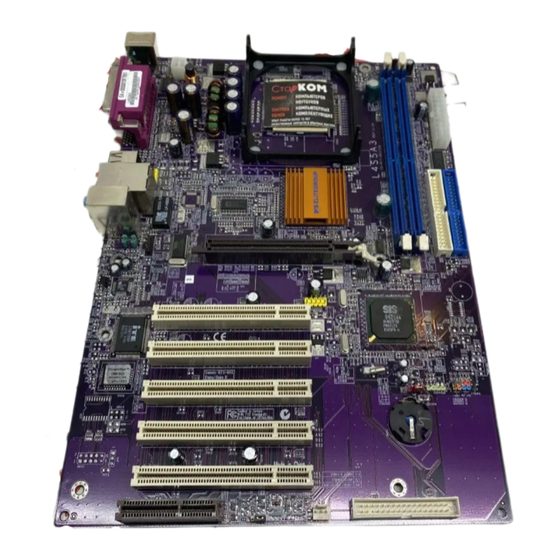
Integrated I/O The mainboard has a full set of I/O ports and connectors: • Two PS/2 ports for mouse and keyboard • One serial port • One parallel port • Four USB ports • One LAN port • Audio jacks for microphone, line-in and line-out BIOS This mainboard uses Award BIOS that enables users to con- Firmware... - Page 10 Table of Mainboard Components Label Component AGP1 Accelerated Graphics Port ATX1 Power connector ATX2 Standard 20-pin ATX Power connector AUDIO1 Front audio connector BAT1 Three volt realtime clock battery CASFAN1 Case fan connector 1 CDIN1 Primary CD-in connector CDIN2 Secondary CD-in connector CNR1 Communications Networking Riser slot COM2*...
-
Page 11: Installing The Mainboard
Installing the Mainboard Follow these safety precautions when installing the mainboard: • Wear a grounding strap attached to a grounded device to avoid damage from static electricity. • Discharge static electricity by touching the metal case of a safely grounded object before working on the mainboard. •... -
Page 12: Installing The Mainboard In A Case
Refer to the following illustration and instructions for installing the mainboard in a case: This illustration shows an ex- 2. Secure the mainboard with ample of a mainboard being screws where appropriate. installed in a tower-type case: Note: Do not overtighten the screws as this can stress the main- board. -
Page 13: Checking Jumper Settings
Checking Jumper Settings The following illustration shows the location of the mainboard jumpers. Pin 1 is labeled. Jumper Settings Jumper Type Description Setting (default) 3-pin Clear CMOS 1-2: Normal 2-3: Clear 3-pin BIOS protect 1-2: Write Enabled 2-3: Write Disabled Jumper 1 –... -
Page 14: Connecting Case Components
After you have installed the mainboard into a case, you can begin connecting the mainboard components. Refer to the following: Connect the Pentium 4 processor auxiliary case power supply connector to ATX1. Connect the standard power supply connec- tor to ATX2. Connect the CPU cooling fan cable to CPUFAN1. - Page 15 CPUFAN1/CASFAN1/PWRFAN1: FAN Power Connectors Signal Name Function System Ground +12V Power +12V Sense Sensor SPEAKER1: Internal speaker Signal Name Signal Ground...
-
Page 16: Front Panel Connector
Front Panel Connector The front panel connector (PANEL1) provides a standard set of switch and LED connectors commonly found on ATX or micro-ATX cases. Refer to the table below for information: PANEL1 Signal Function Signal Function Hard disk LED MSG LED [dual color HD_LED_P FP PWR/SLP (positive) -
Page 17: Installing Hardware
Installing the Processor Caution: When installing a CPU heatsink and cooling fan make sure that you DO NOT scratch the mainboard or any of the surface-mount resistors with the clip of the cooling fan. If the clip of the cooling fan scrapes across the mainboard, you may cause serious damage to the mainboard or its components. - Page 18 CPU Installation Procedure The following illustration shows CPU installation components: Note: The pin-1 corner is marked with an arrow Follow these instructions to install the Retention Module and CPU: Remove the existing retention module (if applicable). Position the backplate against the underside of the mainboard, secure the 4 screws firmly on the retention module.
- Page 19 Locate the CPU cut edge (the corner with the pinhole noticeably miss- ing). Align and insert the CPU correctly. Press the lever down. Apply thermal grease on top of the CPU. Put the CPU Fan down on the retention module and snap the four reten- tion legs of the cooling fan into place.
-
Page 20: Installing Memory Modules
Installing Memory Modules This mainboard accommodates 184-pin 2.5V unbuffered Double Data Rate (DDR) SDRAM memory modules. The memory chips must be standard or registered SDRAM (Synchronous Dynamic Random Access Memory). The memory bus runs at 166 MHz. Note: SDRAM provides 800 MBps or 1 GBps data transfer depending on whether the bus is 100MHz or 133MHz. -
Page 21: Installing A Hard Disk Drive/Cd-Rom
Install the DIMM module into the slot and press it firmly down until it seats correctly. The slot latches are levered upwards and latch on to the edges of the DIMM. Install any remaining DIMM modules. Installing a Hard Disk Drive/CD-ROM This section describes how to install IDE devices such as a hard disk drive and a CD-ROM drive. - Page 22 Installing a Hard Disk Drive Install the hard disk drive into the drive cage in your system case. Plug the IDE cable into IDE1 (A): Note: Ribbon cable connectors are usually keyed so that they can only be installed correctly on the device connector.
-
Page 23: Installing A Floppy Diskette Drive
Installing a Floppy Diskette Drive The mainboard has a floppy diskette drive (FDD1) interface and ships with a diskette drive ribbon cable that supports one or two floppy diskette drives. You can install a 5.25-inch drive and a 3.5-inch drive with various capacities. The floppy diskette drive cable has one type of connector for a 5.25-inch drive and another type of connector for a 3.5-inch drive. - Page 24 PCI Slots PCI slots are used to install expansion cards that have the 32-bit PCI interface. AGP Slot The AGP slot is used to install a graphics adapter that supports the 4xAGP specification and has a 4xAGP edge connector. Note: The layout is for reference only. The AGP slot may be different from your mainboard.
-
Page 25: Connecting Optional Devices
Connecting Optional Devices Refer to the following for information on connecting the mainboard’s optional devices: AUDIO1: Front Panel Audio header This header allows the user to install auxiliary front-oriented microphone and line-out ports for easier access. Signal Name Function AUD_MIC Front Panel Microphone input signal AUD_GND Ground used by Analog Audio Circuits... - Page 26 USB2: Front panel USB ports The mainboard has two USB ports installed on the rear edge I/O port array. Additionally, some computer cases have USB ports at the front of the case. If you have this kind of case, use auxiliary USB connector USB2 to connect the front-mounted ports to the mainboard.
- Page 27 COM2: Onboard serial port connector (optional) Connect a serial port extension bracket to this header to add a second serial port to your system. Signal Name Function NDCDB Data carry detect NSINB Serial Data In NSOUTB Serial Date Out NDTRB Data terminal ready Ground NDSRB...
-
Page 28: Connecting I/O Devices
The backplane of the mainboard has the following I/O ports: PS/2 Mouse Use the upper PS/2 port to connect a PS/2 point- ing device. PS/2 Keyboard Use the lower PS/2 port to connect a PS/2 key- board. LPT1 Use LPT1 to connect printers or other parallel communications devices. -
Page 29: External Connector Color Coding
External Connector Color Coding Many connectors now use standard colors as shown in the table below. Connector Color Audio line-in Light blue Audio line-out Lime Digital monitor/flat panel White IEEE 1394 Grey Microphone Pink MIDI/game Gold Parallel Burgundy PS/2-compatible keyboard Purple PS/2-compatible mouse Green... -
Page 30: Using Bios
Using BIOS The computer uses the latest Award BIOS with support for Windows Plug and Play. The CMOS chip on the mainboard contains the ROM setup instructions for configuring the mainboard BIOS. The BIOS (Basic Input and Output System) Setup Utility displays the system's configuration status and provides you with options to set system parameters. -
Page 31: Entering The Setup Utility
Entering the Setup Utility When you power on the system, BIOS enters the Power-On Self Test (POST) routines. POST is a series of built-in diagnostics performed by the BIOS. After the POST routines are completed, the following message appears: Press DEL to enter SETUP Pressing the delete key accesses the BIOS Setup Utility: Phoenix –... -
Page 32: Using Bios
If your mainboard has an item called Firmware Write Protect in Advanced BIOS features, disable it. (Firmware Write Protect prevents BIOS from being overwritten.) Create a bootable system disk. (Refer to Windows online help for infor- mation on creating a bootable system disk.) Download the Flash Utility and new BIOS file from the manufacturer's Web site. -
Page 33: Standard Cmos Features
Standard CMOS Features This option displays basic information about your system. Phoenix – AwardBIOS CMOS Setup Utility Standard CMOS Features Item Help Date (mm:dd:yy) Tue, July 11 2001 Time (hh:mm:ss) 12 : 8 : 59 Menu Level IDE Primary Master Change the day, month, IDE Primary Slave year and century. - Page 34 IDE HDD Auto-Detection Press <Enter> while this item is highlighted to prompt the Setup Utility to automatically detect and configure an IDE device on the IDE channel. Note: If you are setting up a new hard disk drive that supports LBA mode, more than one line will appear in the parameter box.
-
Page 35: Advanced Bios Features
Advanced BIOS Features This option defines advanced information about your system. Phoenix – AwardBIOS CMOS Setup Utility Advanced BIOS Features Item Help Virus Warning [Disabled] CPU L1 & L2 Cache [Enabled] Menu Level Quick Power On Self Test [Enabled] First Boot Device [Floppy] Allows you to choose Second Boot Device... - Page 36 ing system if it fails to find one in the devices specified under the First, Second, and Third boot devices. Swap Floppy Drive (Disabled) If you have two floppy diskette drives in your system, this item allows you to swap the assigned drive letters so that drive A becomes drive B, and drive B becomes drive A.
-
Page 37: Advanced Chipset Features
S.M.A.R.T. software resides on both the disk drive and the host computer. The disk drive software monitors the internal performance of the motors, me- dia, heads, and electronics of the drive. The host software monitors the overall reliability status of the drive. If a device failure is predicted, the host software, through the Client WORKS S.M.A.R.T applet, warns the user of the impending condition and advises appropriate action to protect the data. - Page 38 Advanced DRAM Control 1 Scroll to this item and press <Enter> to view the following screen: CMOS Setup Utility – Copyright (C) 1984 – 2001 Award Software Advanced DRAM Control 1 Item Help System Performance [Normal Mode] CAS Latency Setting [2.5T] Menu Level DRAM Addr/Cmd Rate...
-
Page 39: Integrated Peripherals
not. Integrated Peripherals These options display items that define the operation of peripheral compo- nents on the system's input/output ports. Phoenix – AwardBIOS CMOS Setup Utility Integrated Peripherals SIS OnChip IDE Device [Press Enter] Item Help SIS OnChip PCI Device [Press Enter] Menu Level Onboard SuperIO Device... - Page 40 Internal PCI/IDE (Both) Use these items to enable or disable the internal PCI IDE channels that are integrated on the mainboard. IDE Primary/Secondary Master/Slave PIO (Auto) Each IDE channel supports a master device and a slave device. These four items let you assign which kind of PIO (Programmed Input/Output) is used by IDE devices.
- Page 41 you are going to install a PCI audio add-on card. SIS-7013 S/W Modem (Enabled) Enables and disables the onboard modem. Disable this item if you are going to install an external modem. SIS-1394 Controller (Disabled) Enables and disables the onboard 1394 controller. Press <Esc>...
- Page 42 Onboard Parallel Port (378/IRQ7) This option is used to assign the I/O address and interrupt request (IRQ) for the onboard parallel port. Parallel Port Mode (ECP) Enables you to set the data transfer protocol for your parallel port. There are four options: SPP (Standard Parallel Port), EPP (Enhanced Parallel Port), ECP (Extended Capabilities Port) and ECP+EPP.
-
Page 43: Power Management Setup
USB0/USB1/USB2 ACCESS INTERFACE (EDB Bus) This option determines whether the USB0/USB1/USB2 access interface is the embedded bus or the PCI bus. USB2.0 ACCESS INTERFACE (EDB BUS) This option determines whether the USB2.0 access interface is the embedded bus or a PCI bus. Audio ACCESS INTERFACE (EDB BUS) This option determines whether the audio access interface is the embedded bus or a PCI bus. - Page 44 ACPI Function (Enabled) This mainboard supports ACPI (Advanced Configuration and Power manage- ment Interface). Use this item to enable or disable the ACPI feature. Note: ACPI is a power management specification that makes hardware status in- formation available to the operating system. ACPI enables a PC to turn its peripherals on and off for improved power management.
- Page 45 down that is controlled by the power button on your system. If the item is set to Instant-Off, then the power button causes a software power down. If the item is set to Delay 4 Sec. then you have to hold the power button down for four seconds to cause a software power down.
- Page 46 Power Up by Alarm (Disabled) When set to Enabled, the following three fields become available: Month Alarm, Day of Month Alarm, and Time Alarm Upon arrival of the alarm time, it will instruct the system to wake up. When set to 0 (zero) for the day of the month, the alarm will power on your system every day at the specified time.
-
Page 47: Pnp/Pci Configurations
PNP/PCI Configurations These options configure how PnP (Plug and Play) and PCI expansion cards oper- ate in your system. Both the ISA and PCI buses on the Mainboard use system IRQs (Interrupt ReQuests) and DMAs (Direct Memory Access). You must set up the IRQ and DMA assignments correctly through the PnP/PCI Configurations Setup utility for the mainboard to work properly. -
Page 48: Pc Health Status
PC Health Status On mainboards that support hardware monitoring, this item lets you monitor the parameters for critical voltages, critical temperatures, and fan speeds. Phoenix – AwardBIOS CMOS Setup Utility PC Health Status Item Help Shutdown Temperature [Disabled] CPU Core Voltage Menu Level 1.8V 3.3V... -
Page 49: Load Fail-Safe Defaults Option
CPU Clock Ratio (0 X) Use the CPU Host/SDRAM/PCI Clock to set the frontside bus frequency for the installed processor (usually 133 MHz, 100 MHz or 66 MHz). Then use CPU Clock Ratio Jumpless to set a multiple. The multiple times the frontside bus must equal the core speed of the installed processor e.g., 3.5 (multiple) x 100 MHz (frontside bus) = 350 MHz (installed processor clock speed). -
Page 50: Set Supervisor/User Password
Set Supervisor/User Password When this function is selected, the following message appears at the center of the screen to assist you in creating a password. ENTER PASSWORD Type the password, up to eight characters, and press <Enter>. The password typed now will clear any previously entered password from CMOS memory. You will be asked to confirm the password. -
Page 51: Using The Mainboard Software
Using the Mainboard Software The support software CD-ROM that is included in the mainboard package contains all the drivers and utility programs needed to properly run the bun- dled products. Below you can find a brief description of each software program, and the location for your mainboard version. -
Page 52: Running Setup
Setup Tab Setup Click the Setup button to run the software installation program. Select from the menu which software you want to install. Browse The Browse CD button is the standard Windows command that allows you to open Windows Explorer and show the contents of the support CD. - Page 53 Note: The following screens are examples only. The screens and driver lists will be different according to the mainboard you are installing. The mainboard identification is located in the upper left-hand corner. Click Next. The following screen appears: Check the box next to the items you want to install. The default options are recommended.
-
Page 54: Manual Installation
Insert the CD in the CD-ROM drive and locate the PATH.DOC file in the root directory. This file contains the information needed to locate the drivers for your mainboard. Look for the chipset and mainboard model; then browse to the directory and path to begin installing the drivers. - Page 55 We strongly recommend users to install this free anti-virus software to help protect your system against viruses. MediaRing Talk – Telephony Software To install the MediaRing Talk voice modem software for the built-in modem, go directory \UTILITY\MEDIARING TALK, then MRTALK- SETUP72.EXE to install the application software.