
Related Manuals for Talon TP-70BS


Summary of Contents for Talon TP-70BS
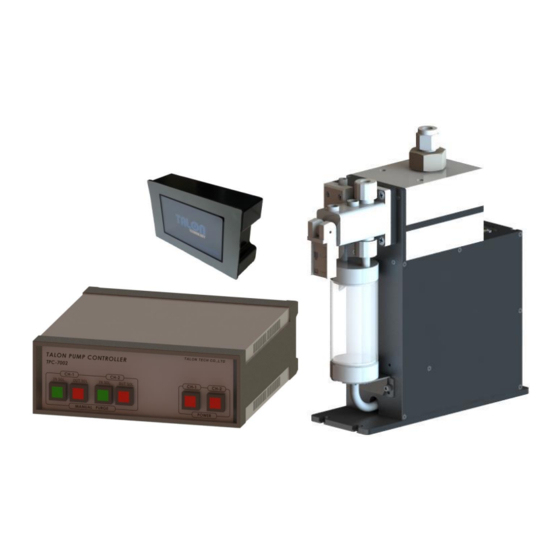
- Page 1 TP-70BS (Rev 3.0) HIGH VISCOSITY & HIGH CAPACITY PR PUMPPump& Controller System MODEL : TP-70BS TALON TECH CO. LTD. TALON TECH CO. LTD.
-
Page 2: Table Of Contents
TP-70BS (Rev 3.0) CONTENTS 1. System Configurations……………………………….…………………………………………………………………………………………. 2. System Specifications……………………………………………………………………………………………………………………………. 2-1. Pump [TP-70BS]…….…………………………………………………………………………………………………………………………. 2-2. Controller [TPC-7002].………..……………………………………………………………………………………………………………. 2-3. Touch Pad [TTP-7008]………………………………………………………………………………………………………………………. 3. System In/Exterior Names………….…………………….………………………………………………………………………………….. 3-1. Pump Exterior Names….…..…………………………………………………………………………………….………………………… 3-1-1. Pump Name Explanation……………………………………………………………………………………….…………………. 3-2. ControllerExterior Names……………………………………………………………………………………………………………..… 3-2-1. Controller Name Explanation……….…………………………………………………………………………………………... 3-3. Touch Pad Exterior Names.………………………………………………………………………………………..…………………….. - Page 3 7-2. Pump Parts Dis/Assembly.…..………..…………………………………………………………………………………………………. 7-2-1. Pump Cover Dis/Assembly..…..…………………….……..…………………………………………………………………….. 7-2-2. Driving Shaft Condition Check & Grease up on Ball Screw……...…………………………………………….. 7-3. Suck-Back Setting………….…………………………………………………………………………………………………………………. 8. Recommended Spares/Mechanical Dimensions…………..…………………………………………………………………….. 8-1. TP-70BS Spare Parts…………………………..…………………………………………………………………………………………….. 8-2. Pump Dimensions………………….………………………………………………………………………………………………………… 8-2-1. Front View…………………….………………………………………………………………………………….………………………... 8-2-2. Side View………...………….……………………………………………………………………………………………………………... 8-3. Controller Dimensions……..…………………………………………………………………………………….………………………...
- Page 4 TP-70BS (Rev 3.0) 8-5. Installation Method……………………………..…………………………………………………………………….…………………….. 8-5-1. Pump Installation Sequence.…..………………………………………………………………………………………………... 8-5-2. Piping Method………..…….…………………………………………………………………………………………………………... 8-5-3. Touch Pad Installation Method…………..…………………………………………………………………………………….. 8-5-4. Suggested Recipe Setting Value…………….………………………………………………………………………………… TALON TECH CO. LTD.
-
Page 5: System Configurations
Max 16ea Pump Control TP-70BS pump can be used as the above configuration and has been developed for the semiconductor system’s automation by operating RS422 communication. Especially, the adoption of servo motor is good for the high degree of PR dispense. The basic communication between the touch pad and the pump is RS422 Multi Drop method. -
Page 6: System Specifications
TP-70BS (Rev 3.0) System Specifications 2-1Pump[ TP-70BS ] ITEM SPEC REMARKS Dispense Volume Range 1.0cc ~ 20cc Dispense/ Reload Rate 0.3 cc/sec ~ 1.2 cc/sec Dispense Volume Resolution 0.01 cc Dispense Repeatability ≤±0.04(Polyimide PIX/PIQ) Viscosity 50cp ~ 20,000cp Drive System... -
Page 7: Controller [Tpc-7002]
TP-70BS (Rev 3.0) 2-2 Controller [ TPC-7002 ] ITEM SPEC REMARKS Electric Power 85VAC ~ 264VAC, 50~60Hz Controller Power DC 24V (current consumption Max 1A) Panel Use Drive Pump No. 2 Pumps Pump Operation Mode Fixed Mode Main CPU 80c296 (16bit Processor) 1. -
Page 8: Systemin/Exterior Names
TP-70BS (Rev 3.0) SystemIn/Exterior Names 3-1 Pump In/Exterior Names ② PR Out ⅜” ③ PR Drain ⅜” ①PR In ⅜” ⑥ Pump CON ④ Toggle Valve ⑤ Buffer Tank 3-1-1 Pump Name Explanation ① PR In - ChemicalSupply. (⅜ Inch Teflon) ②PR Out... -
Page 9: Controllerexterior Names
TP-70BS (Rev 3.0) 3-2 ControllerExterior Names ① ② ③ ④ ⑤ ⑥ [TPC-7002Front View] ⑪ ⑨ ⑦ ⑧ ⑩ [TPC-7002Rear View] 3-2-1 Controller Name Explanation ①CH-1 In Sol S/W - After CH-1 Pump Dispense, LED Lamp Switch for Reload Operation Condition. -
Page 10: Touch Pad Exterior Names
TP-70BS (Rev 3.0) - CH-1 Pump Connector. (D-SUB 15P Female) - CH-1 Track I/O Connector. (D-SUB 15P Female) - CH-1 Touch Pad RS-422 Communication Connector. (D-SUB 9P Female) ⑩ CH-2 Pump, Track I/O, COM - CH-2 Pump Connector. (D-SUB 15P Female) - CH-2 Track I/O Connector. -
Page 11: Track/Auxiliary Interface
TP-70BS (Rev 3.0) Track / Auxiliary Interface 4-1 Track Interface Signal “0” Trigger Off Recipe Select Trigger “1” Trigger On Recipe Start1 Start2 Start3 Remark Select Not support It is Timing Chart. On Readycondition, when Start Signal becomes active, each signal is same as the chart. -
Page 12: Track Interface Wiring
TP-70BS (Rev 3.0) 4-2Track InterfaceWiring Controller Side Track Side <Stop / WarningActive High> <End / Home Active Low> <Start1, 2, 3 Active Low> - 8 - TALON TECH CO. LTD. -
Page 13: Cable Pin Assign
TP-70BS (Rev 3.0) 4-3 Cable Pin Assign 4-3-1 Pump Cable Standard Type(D-SUB 15P) Number Controller Pump 1 : 1 PUMP_CW 1 : 1 PUMP_CCW 1 : 1 +24V 1 : 1 E_HOME_SIGNAL 1 : 1 E_END_SIGNAL 1 : 1 E_MOTOR_ALARM... -
Page 14: Track Cable
TP-70BS (Rev 3.0) 4-3-2Track Cable Standard Type(D-SUB 15P) Number Signal Name Description Output Output Option Alarm Output START 3 Input Recipe Select Signal START 1 Input START 2 Input OUT SOL Output ALARM STOP Output Pump Alarm(Pump Stop) ALARM WARNING... - Page 15 TP-70BS (Rev 3.0) Encompass Type(Hirose 20P) Number Controller Track (ACT-12) Connecting Way Not Use Not Use Not Use Not Use START 1 Pump I/O Board START 2 ↓ OUT SOL V/V 6 => Jump to END 7 Pump I/O CONN Board ALARM STOP ↓...
-
Page 16: Touch Pad Cable
TP-70BS (Rev 3.0) 4-3-3 Touch Pad Cable 4-3-4COM Cable - 12 - TALON TECH CO. LTD. -
Page 17: External Cable Length
TP-70BS (Rev 3.0) External Cable Length 5-1 Pump Cable 5-2Track Cable Standard Type Mark Type ACT Type ACT Encompass Type - 13 - TALON TECH CO. LTD. -
Page 18: Touch Pad Cable
TP-70BS (Rev 3.0) 5-3Touch Pad Cable Pump 2ea Standard Type Touch Pad Cable in case of over 3 pumps in use 5-4 COM Cable Cablein case of over 3 pumps in use - 14 - TALON TECH CO. LTD. -
Page 19: Communication Cable Connection Method
TP-70BS (Rev 3.0) 5-5 Communication Cable Connection Method In case of 2 pumps in use In case of over 3 pumps in use - 15 - TALON TECH CO. LTD. -
Page 20: Touch Pad Operation
TP-70BS (Rev 3.0) Touch Pad Operation 6-1 Operation 6-1-1 Initial Screen The pumps’ ID, which are cable-connected to touch pad, are auto-searched every 5 sec. On every lower menu, if there isn’t any input for 1 min, the initial screen is back. The pump, which is not searched, cannot be chosen. -
Page 21: Select Function
TP-70BS (Rev 3.0) 6-1-3Select Function When ID is chosen, the above screen is shown. Go to the previous menu. Dispense Dispense by touching the pad. Recipe Run Recipe & Dispense Recipe Setting. Config Pump Mode, Reset, Error & ID Setting. -
Page 22: Recipe Setting
TP-70BS (Rev 3.0) 6-1-5 Recipe Setting For Recipe Setting, touch # under No. and input recipe # that you want to go in and touch ‘Ent’. At this time, Recipe Data is automatically shown on the screen. And you can input the data that you want and touch ‘set’... -
Page 23: Config Pump
TP-70BS (Rev 3.0) 6-1-6 Config Pump On Config Pump, the password needs for the important items’ set. The password is set as ‘0901’. Vital Check pump’s response and in case of response, ‘vital’ window activates and disappears right away. At the left window, the response data is shown. -
Page 24: Maint Mode, Run Mode, Pump Reset Setting
TP-70BS (Rev 3.0) On Config Pump screen, when you touch ‘Set ID’, Password input screen shows and input ‘0901’and touch Ent. And then, ‘Check ID’‘Set ID’ screen shows and disappears right away so the initial starts. If there is no response from the pump, the window keeps showing. If there is already the same pump ID, the window –‘Conflict’... -
Page 25: Calibration
TP-70BS (Rev 3.0) 6-1-7 Calibration Calibration –Per each Recipe, it is possible to set the calibration value. If there is the differences between the real value and the setting value, set the calibration value higher or lower % at the standard- 100.. - Page 26 TP-70BS (Rev 3.0) After clicking Set, the window goes to Password window. The setting value is adopted after inputting “2580”. Cancel button means no application even Limit change & Count Zero click. When dispense # goes over Limit Setting value, “Count Over” shows on Main Menu and also shows on Touch pad.
-
Page 27: Example
TP-70BS (Rev 3.0) 6-2 Example 6-2-1Dispense If you want to dispense one time, use Start Run. This recipe is Run recipe which set on Recipe menu. Start Cycle below is 4 Recipe. Stop Cycle only works the case of using Start Cycle. Keep touching Stop Cycle button. -
Page 28: Recipe Setting
TP-70BS (Rev 3.0) 6-2-2 Recipe Choose the recipe # and touch ‘Ent’ button. The chosen recipe data is automatically read from the pump. Set the recipe’s volume & time and touch ‘Set’ button. - 24 - TALON TECH CO. LTD. -
Page 29: Id Setting
TP-70BS (Rev 3.0) 6-2-3ID Setting Choose ID # which you want to change from 11~44. ID consists of 2 digits. The 2 digit means Coater# and the 1 digit means Nozzle#. Total 16 ID setting is possible. [Password :0901] - 25 -... -
Page 30: Name Setting
TP-70BS (Rev 3.0) When ID changes, check the automatic pump initialization and the change is applied on Main Menu. Nozzle Name Re Check. 6-2-4Name Setting The pump name can be changed on Main Menu and the max digit is 18~25. -
Page 31: Cycle Purge Method
TP-70BS (Rev 3.0) 6-3 Cycle Purge Method 1. Choose the pump nozzle for the cycle purge. - Pump condition is same as Ready of [PIC 1]. * On Busy condition, Cycle Start cannot be done on the screen. [PIC1] 2. Under Select Function, touch Recipe button. - Page 32 TP-70BS (Rev 3.0) 6. Input Recipe Data to be changed. - Count means Dispense #. - In case of Count #10 and Start Cycle on Dispense menu, Recipe #4 executes 10 times of Dispense. - Reload Volume inputs same as Disp. Volume automatically.
-
Page 33: Reset On Pump Error
TP-70BS (Rev 3.0) 6-4 Reset on Pump Error 1. Choose the alarmed pump. [PIC1] 2. Touch Config button on Select Function menu. [PIC2] 3.Touch OK button“Are you Sure?” window. - Right after touching OK, Reset progresses and Alarm is clear. -
Page 34: Log Data
1. Set the date to check out. 2. Set ID to check out. (In case of ‘ 0 ‘, search all ID) 3. Click Query. The contents are shown as Text /Code. Contact Talon for detail. - 30 - TALON TECH CO. LTD. -
Page 35: Log Data Analysis
TP-70BS (Rev 3.0) 6-5-1Log Data Analysis At the right of date & time, there are ' O ' , ' I ' , &' U '. 1. [ O] Touch Pad(Command) -> Controller. 2. [ I] Touch Pad <- Controller. (Response) 3. -
Page 36: Touch Pad Menu Tree
TP-70BS (Rev 3.0) 6-6Touch Pad Menu Tree 6-7Notice 6-7-1 Dispense Cycle During the system or the manual dispense, the pump doesn’t save Recipe changes and setting changes. At this time, ‘Busy’ window is shown normally. 6-7-2 Pump ID Setting The basic ID is ‘11’. If pump & touch pad is set in the first time, connect pump & touch pad as 1:1 not to double ID. -
Page 37: Notice On Pump Operation
TP-70BS (Rev 3.0) Notice on Pump Operation 1. During Pump is under process (RUN OR CYCLE) don’t try to modify the data. (Please do it after Pump had stop properly) ▶ In this term of “modify data” means changing recipe, cycle, CAL value etc. If you modified the data during pump operation, BUSY screen will be pop-up and it will be not saved. -
Page 38: Maintenance
TP-70BS (Rev 3.0) Maintenance 7-1 Manual Purge Method N2 Press [PIC 1] ① ② [PIC 2] In order to purge, press N2 into PR bottle as per [PIC 1] and push ②(OUT SOL) Button of Manual Purge S/W as per [PIC 2] to open Suck Back Valve. -
Page 39: Pump Parts Dis/Assembly
TP-70BS (Rev 3.0) 7-2 Pump Parts Dis/Assembly 7-2-1 Pump Cover Dis/Assembly 1. As per the below [PIC 1], use 2mm wrench to release Pump Cover Mounting M3Screw(14ea) to open the cover. 2. The assembly is the reverse order of the disassembly. -
Page 40: Suck-Back Setting
TP-70BS (Rev 3.0) 7-3 Suck-Back Setting ③ Suck-Back Volume (Adjust Suck-Back) ③-① Lock Nut ② Cut Off (PR Cut Timing) ②-① Lock Nut ④ Suck-Back Speed (Adjust Suck-Back speed) ④-① Lock Nut Main Air Inlet ① Main Air (Adjust overall Air volume) ①-①... - Page 41 TP-70BS (Rev 3.0) 8. Fasten every knob’s lock nut. (①-①, ②-①, ③-①, ④-①) 9. Dispense resist again to final check. 10. If value is not correct, go back to order NO.3. ⚫ REFERENCES FOR WORKING SEQUENCE ②, ③ ① ④...
-
Page 42: Recommended Spares/Mechanical Dimensions
TP-70BS (Rev 3.0) Recommended Spares / Mechanical Dimensions 8-1TP-70BS Spare Parts Division Part NO. Description TL-70BS-TA-001 Cylinder TL-70BS-TA-006 Outer Type Edgeless Bellows TL-70BS-CA-001 Toggle Valve TL-70BS-MA-001 Ball Screw TL-70BS-MA-002 Support Unit TL-70BS-EB-001 Motor TL-70BS-MA-003 LM Guide Pump TL-70BS-ET-001 Timing Belt... -
Page 43: Pump Dimensions
TP-70BS (Rev 3.0) 8-2 Pump Dimensions 8-2-1 Front View 8-2-2 Side View - 39 - TALON TECH CO. LTD. -
Page 44: Controller Dimensions
TP-70BS (Rev 3.0) 8-3 Controller Dimensions 8-3-1 Front View 8-3-2 Rear View 8-3-3 Side View - 40 - TALON TECH CO. LTD. -
Page 45: Touch Pad Dimensions
TP-70BS (Rev 3.0) 8-4 Touch Pad Dimensions 8-4-1 Front View 8-4-2 Rear View 8-4-3 Side View - 41 - TALON TECH CO. LTD. -
Page 46: Installation Method
TP-70BS (Rev 3.0) 8-5 Installation Method 8-5-1 Pump Installation Sequence 1. Prepare the space for the pump installation. 2. As per the below picture, tighten the panel base plate with 4 pieces of M4 screw. Make 3.4mm hole and Tap M4... -
Page 47: Touch Pad Installation Method
TP-70BS (Rev 3.0) 8-5-3Touch Pad Installation Method [PIC 1] Equipment-side Panel Back Cover Bolt: M3x8 Touch Pad [PIC 2] [PIC 3] 1. As per [PIC 1], peel the sticker a little until the screw is seen. And loose the screw to take the back cover apart. -
Page 48: Suggested Recipe Setting Value
TP-70BS (Rev 3.0) 8-5-4 Suggested Recipe Setting Value (PR viscosity: 1,800cP) Volume Dispense/Time Reload/Time Data Input Data Input Data Input (Sec) (Sec) 1700 1800 1900 2000 2100 2200 2300 2400 10.5 1050 2500 1000 11.5 1150 2600 1100 12.5 1250... - Page 49 TP-70BS (Rev 3.0) Dispense time(D/T) formula : Volume(g)+1.5=D/T =>ex) 18+1.5=19.5 Reload time formula : Volume(g)+16=R/T =>ex) 18+16=34 ※ The above data is based on 1,800cP. It is supposed to be changed upon cP. <THEN END> - 45 - TALON TECH CO. LTD.