Table of Contents
Advertisement
Quick Links
Copyright
This publication, including all photographs, illustrations and software, is protected under
international copyright laws, with all rights reserved. Neither this manual, nor any of the
material contained herein, may be reproduced without written consent of the author.
Version 1.0
Disclaimer
The information in this document is subject to change without notice. The manufacturer
makes no representations or warranties with respect to the contents hereof and specifically
disclaims any implied warranties of merchantability or fitness for any particular purpose.
The manufacturer reserves the right to revise this publication and to make changes from
time to time in the content hereof without obligation of the manufacturer to notify any
person of such revision or changes.
Trademark Recognition
Microsoft, MS-DOS and Windows are registered trademarks of Microsoft Corp.
MMX, Pentium, Pentium-II, Pentium-III, Pentium 4, Celeron are registered trademakrs of
Intel Corporation.
Other product names used in this manual are the properties of their respective owners and
are acknowledged.
Federal Communications Commission (FCC)
This equipment has been tested and found to comply with the limits for a Class B digital
device, pursuant to Part 15 of the FCC Rules. These limits are designed to provide reason-
able protection against harmful interference in a residential installation. This equipment
generates, uses, and can radiate radio frequency energy and, if not installed and used in
accordance with the instructions, may cause harmful interference to radio communications.
However, there is no guarantee that interference will not occur in a particular installation.
If this equipment does cause harmful interference to radio or television reception, which
can be determined by turning the equipment off and on, the user is encouraged to try to
correct the interference by one or more of the following measures:
•
Reorient or relocate the receiving antenna.
•
Increase the separation between the equipment and the receiver.
•
Connect the equipment onto an outlet on a circuit different from that to which
the receiver is connected.
•
Consult the dealer or an experienced radio/TV technician for help.
Shielded interconnect cables and a shielded AC power cable must be employed with this
equipment to ensure compliance with the pertinent RF emission limits governing this
device. Changes or modifications not expressly approved by the system's manufacturer
could void the user's authority to operate the equipment.
Preface
Preface
Advertisement
Table of Contents

Related Manuals for ECS 651C-M


Summary of Contents for ECS 651C-M
- Page 1 Preface Copyright This publication, including all photographs, illustrations and software, is protected under international copyright laws, with all rights reserved. Neither this manual, nor any of the material contained herein, may be reproduced without written consent of the author. Version 1.0 Disclaimer The information in this document is subject to change without notice.
- Page 2 Declaration of Conformity This device complies with part 15 of the FCC rules. Operation is subject to the following conditions: • This device may not cause harmful interference, and • This device must accept any interference received, including interference that may cause undesired operation. Canadian Department of Communications This class B digital apparatus meets all requirements of the Canadian Interference-causing Equipment Regulations.
-
Page 3: Table Of Contents
T T T T T ABLE OF CONTENTS ABLE OF CONTENTS ABLE OF CONTENTS ABLE OF CONTENTS ABLE OF CONTENTS Preface Chapter 1 Introducing the Motherboard Introduction....................1 Features.......................2 Motherboard Components...............4 7 7 7 7 7 Chapter 2 Installing the Motherboard Safety Precautions..................7 Choosing a Computer Case...............7 Installing the Motherboard in a Case............7... - Page 4 Integrated Peripherals..............32 Power Management Setup............36 PNP/PCI Configurations.............38 PC Health Status................39 Frequency/Voltage Control............40 Load Fail-Safe Defaults..............41 Load Optimized Defaults.............41 Set Supervisor/User Password............41 Save & Exit Setup Option.............41 Exit Without Saving..............42 43 43 43 43 Chapter 4 Using the Motherboard Software About the Software CD-ROM..............43 Auto-installing under Windows 98/ME/2000/XP........43 Running Setup................44 Manual Installation..................46...
-
Page 5: Introducing The Motherboard
Chapter 1 Introducing the Motherboard Introduction Thank you for choosing the 651C-M mainboard. This micro-ATX mainboard comes with the high performance SiS651C Northbridge and SiS962L Southbridge chipsets. It accommo- dates Intel Pentium 4 processors with Hyper-Threading (HT) supported, which supports the frontside bus (FSB) speeds up to 533/400 MHz. -
Page 6: Features
Feature Processor 651C-M uses a 478-pin socket that carries the following features: • Supports P4 processors at 1.5GHz up to 3.2GHz • Supports Hyper-Threading technology CPU • Supports 533/400 MHz front side bus (FSB) “Hyper-Threading” technology enables the operating system to think it’s hooked up to two threads to be run in parallel, both on seperate “logical”... - Page 7 Expansion Options The motherboard comes with the following expansion options: • Three 32-bit PCI slots • One AGP slot • Two IDE headers which support four IDE devices • One floppy disk drive interface • A Communications Networking Riser (CNR) slot •...
-
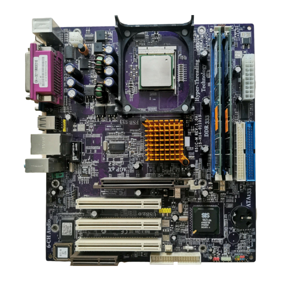
Page 8: Motherboard Components
Motherboard Components Introducing the Motherboard... - Page 9 Table of Motherboard Components LABEL COMPONENT 1 CPU Socket Socket 478 for Intel Pentium 4 processor 2 DIMM1~2 184-pin DDR SDRAM slots 3 CPUFAN1 CPU cooling fan connector 4 ATX2 Standard 20-pin ATX power connector 5 IDE2 Secondary IDE connector 6 IDE1 Primary IDE connector 7 AGP1...
- Page 10 Memo Introducing the Motherboard...
-
Page 11: Installing The Motherboard
Make sure that your case supports all the features required. Secondly, 651C-M supports one or two floppy diskette drives and four IDE drives. Make sure that your case has sufficient power and space for all drives that you intend to install. -
Page 12: Checking Jumper Settings
Do not over-tighten the screws as this can stress the motherboard. Checking Jumper Settings This section explains how to set jumpers for correct configuration of the motherboard. Setting Jumpers Use the motherboard jumpers to set system configuration options. Jumpers with more than one pin are numbered. -
Page 13: Checking Jumper Settings
Checking Jumper Settings The following illustration shows the location of the motherboard jumpers. Pin 1 is labeled. Jumper Settings Jumper Type Setting (default) Description 3-pin CLEAR CMOS 1-2: Normal 2-3: Clear CMOS Before clearing the CMOS, make sure to turn the sys- tem off. -
Page 14: Connecting Case Components
Connecting Case Components After you have installed the motherboard into a case, you can begin con- necting the motherboard components. Refer to the following: Connect the CPU cooling fan cable to CPUFAN1. Connect the case cooling fan connector to CASFAN1. Connect the case speaker cable to SPK1. -
Page 15: Front Panel Header
SPK1: Internal speaker Signal Name Ground Signal ATX12V: ATX 12V Power Connector Signal Name Ground Ground +12V +12V ATX1: ATX 20-pin Power Connector Signal Name Signal Name +3.3V +3.3V +3.3V -12V Ground Ground PS ON# Ground Ground Ground Ground Ground PWRGD +5VSB +12V... -
Page 16: Installing Hardware
Pin Signal Name Function Pin Signal Name Function HD_LED_P Hard disk LED(+) 2 FP PWR/SLP *MSG LED(+) HD_LED_N Hard disk LED(-) FP PWR/SLP *MSG LED(-) RST_SW_N Reset Switch(-) PWR_SW_P Power Switch(+) RST_SW_P Reset Switch(+) PWR_SW_N Power Switch(-) RSVD Reserved 10 Key No pin * MSG LED (dual color or single color) Hard Drive Activity LED... - Page 17 Before installing the Processor This motherboard automatically determines the CPU clock frequency and system bus frequency for the processor. You may be able to change these settings by making changes to jumpers on the motherboard, or changing the settings in the system Setup Utility. We strongly recommend that you do not over-clock processors or other components to run faster than their rated speed.
-
Page 18: Installing Memory Modules
Installing Memory Modules 651C-M accommodates two 184-pin 2.5V unbuffered Double Data Rate (DDR) SDRAM (Synchronous Dynamic Random Access Memory) memory modules. 651C-M can support DDR333/DDR266/DDR200 memory types and its total maximum memory size is 2 GB. DDR SDRAM memory module table... -
Page 19: Installing A Hard Disk Drive/Cd-Rom
Installing a Hard Disk Drive/CD-ROM This section describes how to install IDE devices such as a hard disk drive and a CD-ROM drive. About IDE Devices Your motherboard has a primary and secondary IDE channel interface (IDE1 and IDE2). An IDE ribbon cable supporting two IDE devices is bundled with the motherboard. You must orient the cable connector so that the pin1 (color) edge of the cable correspoinds to the pin 1 of the I/O port connector. -
Page 20: Installing A Floppy Diskette Drive
Installing a Floppy Diskette Drive The motherboard has a floppy diskette drive (FDD) interface and ships with a diskette drive ribbon cable that supports one or two floppy diskette drives. You can install a 5.25-inch drive and a 3.5-inch drive with various capacities. The floppy diskette drive cable has one type of connector for a 5.25-inch drive and another type of connector for a 3.5-inch drive. - Page 21 Follow these instructions to install an add-on card: Remove a blanking plate from the system case corresponding to the slot you are going to use. Install the edge connector of the add-on card into the expansion slot. Ensure that the edge connector is correctly seated in the slot. Secure the metal bracket of the card to the system case with a screw.
-
Page 22: Connecting Optional Devices
Connecting Optional Devices Refer to the following for information on connecting the motherboard’s optional devices: AUDIO1: Front Panel Audio header This header allows the user to install auxiliary front-oriented microphone and line-out ports for easier access. Signal Name Signal Name Function AUD_MIC Front Panel Microphone input signal... - Page 23 USB3: Front Panel USB header The motherboard has four USB ports installed on the rear edge I/O port array. Additionally, some computer cases have USB ports at the front of the case. If you have this kind of case, use auxiliary USB connector to connect the front-mounted ports to the motherboard. Signal Name Function USBPWR...
-
Page 24: Connecting I/O Devices
Connecting I/O Devices The backplane of the motherboard has the following I/O ports: PS2 Mouse Use the upper PS/2 port to connect a PS/2 pointing device. PS2 Keyboard Use the lower PS/2 port to connect a PS/2 keyboard. Parallel Port (LPT1) Use LPT1 to connect printers or other parallel communications devices. -
Page 25: Using Bios
Chapter 3 Using BIOS About the Setup Utility The computer uses the latest Award BIOS with support for Windows Plug and Play. The CMOS chip on the motherboard contains the ROM setup instructions for configuring the motherboard BIOS. The BIOS (Basic Input and Output System) Setup Utility displays the system’s configura- tion status and provides you with options to set system parameters. - Page 26 Press DEL to enter SETUP Pressing the delete key accesses the BIOS Setup Utility: Phoenix-AwardBIOS CMOS Setup Utility: Standard CMOS Features Frequency/Voltage Control Advanced BIOS Features Load Fail-Safe Defaults Advanced Chipset Features Load Optimized Defaults Integrated Peripherals Set Password Power Management Setup Save &...
-
Page 27: Updating The Bios
Updating the BIOS You can download and install updated BIOS for this motherboard from the manufacturer’s Web site. New BIOS provides support for new peripherals, improvements in performance, or fixes for known bugs. Install new BIOS as follows: If your motherboard has a BIOS protection jumper, change the setting to allow BIOS flashing. -
Page 28: Standard Cmos Features
Standard CMOS Features This option displays basic information about your system. Phoenix-AwardBIOS CMOS Setup Utility Standard CMOS Features Date (mm:dd:yy) Wed, Feb 25 2004 Item Help Time (hh:mm:ss) 9 : 33 : 26 Menu Level IDE Channel 0 Master IDE Channel 0 Slave Change the day, month, IDE Channel 1 Master year and century... - Page 29 IDE Channel 0/1 Master/Slave/ IDE Drive(Auto) Leave this item at Auto to enable the system to automatically detect and configure IDE devices on the channel. If it fails to find a device, change the value to Manual and then manually configure the drive by entering the characteristics of the drive in the items described below.
-
Page 30: Advanced Bios Features
Advanced BIOS Features This option defines advanced information about your system. Phoenix-AwardBIOS CMOS Setup Utility Advanced BIOS Features CPU Feature [Press Enter] Hard Disk Boot Priority [Press Enter] Item Help CPU L1 & L2 Cache [Enabled] CPU L3 Cache [Enabled] Menu Level Hyper-Threading Technology [Enabled]... - Page 31 Hard Disk Boot Priority (Press Enter) Scroll to this item and press <Enter> to view the following screen: Phoenix-AwardBIOS CMOS Setup Utility Hard Disk Boot Priority 1. Pri.Master: Item Help 2. Pri.Slave: Menu Level 3. Sec. Master: 4. Sec. Slave: Use <...
- Page 32 Boot Up Floppy Seek (Disabled) If this item is enabled, it checks the size of the floppy disk drives at start-up time. You don’t need to enable this item unless you have a legacy diskette drive with 360K capacity. Boot Up NumLock Status (On) This item defines if the keyboard Num Lock key is active when your system is started.
-
Page 33: Advanced Chipset Features
Advanced Chipset Features These items define critical timing parameters of the motherboard. You should leave the items on this page at their default values unless you are very familiar with the technical specifications of your system hardware. If you change the values incorrectly, you may introduce fatal errors or recurring instability into your system. - Page 34 • DRAM CAS Latency (2.5T): This item controls the timing delay (in clock cycles) before the DRAM starts a read command after receiving it. • RAS Active Time (tRAS) (6T): This item allows you to set the amount of time a RAS can be kept open for multiple accesses.
- Page 35 OnChip AGP Control Scroll to this item and press <Enter> to view the following screen: Phonix - AwardsBIOS CMOS Setup Utility OnChip AGPControl Item Help VGA Share Memory Size [32MB] Full Screen Logo [Disabled] Menu Level : Move Enter: Select +/-/PU/PD:Value F10:Save ESC:Exit F1: General Help F5:Previous Values F6:Fail-Safe Defaults F7:Optimized Defaults...
-
Page 36: Integrated Peripherals
Integrated Peripherals These options display items that define the operation of peripheral components on the system’s input/output ports. Phoenix-AwardBIOS CMOS Setup Utility Integrated Peripherals OnChip IDE Device [Press Enter] Item Help OnChip PCI Device [Press Enter] Menu Level Onboard SuperIO Device [Press Enter] Onboard LAN Device [Enabled]... - Page 37 IDE DMA Transfer Access (Enabled) This item allows you to enabled the transfer access of the IDE DMA. IDE Burst Mode (Enabled) This option, when enabled will instruct the system to send every write transaction to the write buffer. Burstable transactions then burst onto the PCI bus and nonburstable transactions do not. Press <Esc>...
- Page 38 Onboard SsuperIO Device (Press Enter) Scroll to this item and press <Enter> to view the following screen: Phoenix-AwardBIOS CMOS Setup Utility SuperIO Device Item Help Onboard FDC Controller [Enabled] Onboard Serial Port 1 [3F8/IRQ4] Menu Level UART Mode Select [Normal] UR2 Duplex Mode [Half] Onboard Parallel Port...
- Page 39 Onboard LAN Device (Enabled) Use this item to enable and disable the onboard LAN function. IDE HDD Block Mode (Enabled) Enable this field if your IDE hard drive supports block mode. Block mode enables BIOS to automatically detect the optimal number of block read and writes per sector that the drive can support.
-
Page 40: Power Management Setup
Power Management Setup This option lets you control system power management. The system has various power- saving modes including powering down the hard disk, turning off the video, suspending to RAM, and software power down that allows the system to be automatically resumed by certain events. - Page 41 Power On After Power Fail (Always Off) This item enables your computer to automatically restart or return to its last operationg status after power returns from a power failure. PM Wake Up Events (Press Enter) Phoenix-AwardBIOS CMOS Setup Utility PM Wake Up Events IRQ [3-7, 9-15], NMI [Enabled] Item Help...
-
Page 42: Pnp/Pci Configurations
FDD, COM, LPT Port (Disabled) When this item is enabled, the system will restart the power-saving timeout counters when any activity is detected on the floppy disk drive, serial ports, or the parallel port. PCI PIRQ[A-D]# (Disabled) When disabled, any PCI device set as the Master will not power on the system. Press <Esc>... -
Page 43: Pc Health Status
PCI/VGA Palette Snoop [Disabled] This item is designed to overcome problems that can be caused by some non-standard VGA cards. This board includes a built-in VGA system that does not require palette snooping so you must leave this item disabled. Assign IRQ For USB [Enabled] Names the interrupt request (IRQ) line assigned to the USB on your system. -
Page 44: Frequency/Voltage Control
Frequency/Voltage Control This item enables you to set the clock speed and system bus for your system. The clock speed and system bus are determined by the kind of processor you have installed in your system. Phoenix-AwardBIOS CMOS Setup Utility Frequency/Voltage Control CPU Clock Ratio [ 0 X]... -
Page 45: Load Fail-Safe Defaults
Load Fail-Safe Defaults This option opens a dialog box that lets you install fail-safe defaults for all appropriate items in the Setup Utility: Press <Y> and the <Enter> to install the defaults. Press <N> and then <Enter> to not install the defaults. The fail-safe defaults place no great demands on the system and are generally stable. -
Page 46: Exit Without Saving
Exit Without Saving Highlight this item and press <Enter> to discard any changes that you have made in the Setup Utility and exit the Setup Utility. When the Exit Without Saving dialog box appears, press <Y> to discard changes and exit, or press <N> to return to the main menu. -
Page 47: Using The Motherboard Software
Chapter 4 Using the Motherboard Software About the Software CD-ROM The support software CD-ROM that is included in the motherboard package contains all the drivers and utility programs needed to properly run the bundled products. Below you can find a brief description of each software program, and the location for your motherboard version. -
Page 48: Running Setup
Setup Tab Setup Click the Setup button to run the software installation program. Select from the menu which software you want to install. Browse CD The Browse CD button is the standard Windows command that allows you to open Windows Explorer and show the contents of the support Before installing the software from Windows Explorer, look for a file named README.TXT, INSTALL.TXT or something similar. - Page 49 Click Next. The following screen appears: Check the box next to the items you want to install. The default options are recommended. Click Next run the Installation Wizard. An item installation screen appears: Follow the instructions on the screen to install the items. Drivers and software are automatically installed in sequence.
-
Page 50: Manual Installation
Manual Installation Insert the CD in the CD-ROM drive and locate the PATH.DOC file in the root directory. This file contains the information needed to locate the drivers for your motherboard. Look for the chipset and motherboard model; then browse to the directory and path to begin installing the drivers. - Page 51 Caractéristiques Processeur 651C-M utilise un socket 478broches présentant les caractéristiques suivantes: • Prend en charge les processeurs P4 de 1.5GHz jusqu’ à 3.2GHz • Prend en charge le CPU de technologie Hyper-Threading • Prend en charge un bus frontal (FSB) de 533/400 MHz La technologie “Hyper-Threading”...
- Page 52 Options d’extension La carte mère comporte les options d’extension suivantes : • Trois emplacements PCI 32 bits • Un emplacement AGP • Deux barrettes IDE avec prise en charge de quatre périphériques IDE • Une interface lecteur de disquettes • Un logement Communications Network Riser (CNR) •...
- Page 53 Leistungsmerkmale Prozessor 651C-M verwendet einen 478-Pin Sockel mit den folgenden Eigenschaften: • Unterstützt P4-Prozessoren von 1.5GHz bis zu 3.2GHz • Unterstützt Hyper-Threading Technology CPU • Unterstützt 533/400 MHz Front Side Bus (FSB) “Hyper-Threading”-Technologie läßt das Betriebssystem glauben, es sei an zwei Prozessoren angeschlossen, was zwei parallele Threads auf separaten ‘logischen’...
- Page 54 Erweiterungsmöglichkeiten Das Motherboard ist mit den folgenden Erweiterungsmöglichkeiten ausgestattet: • Drei 32-Bit PCI-Steckplätze • Ein AGP-Steckplatz • Zwei IDE-Anschlüsse für vier IDE-Geräte • Ein Diskettenlaufwerkanschluss • Einen Steckplatz für Communications Network Riser (CNR) • Ein Card Reader-USB-Header Das Motherboard unterstützt Ultra DMA-Busmaster mit Transferraten von 133/100/66 /33MB/s.
- Page 55 Caratteristiche Processore 651C-A utilizza un Socket a 478 pin che supporta le seguenti caratteristiche: • Supporta processori P4 da 1,5GHz sino a 3,2GHz • Supporta CPU con tecnologia Hyper-Threading (HT) • Supporta FSB da 533/400 MHz La tecnologia “Hyper-Threading” (HT) abilita il sistema operativo a credere di essere collegato a due processori, consentendo di eseguire in parallelo due Thread, entrambi su processori “logici”...
- Page 56 Opzioni d’espansione La scheda madre è dotata delle seguenti opzioni d’espansione: • Tre alloggiamenti PCI 32 bit • Un alloggiamento AGP • Due collettori IDE che supportano quattro dispositivi IDE • Una interfaccia unità dischetti floppy • Una slot Communications Network Riser (CNR) •...
- Page 57 Función Procesador 651C-M utiliza un receptáculo de 478 pins que tiene las caracterí sticas siguientes: • Soporta procesadores P4 de 1.5GHz hasta 3.2GHz • Soporta CPU de la tecnologí a Hyper-Threading (Hiperhilado) • Soporta bus de lado frontal (FSB) de 533/400 MHz La tecnología “Hyper-Threading”...
- Page 58 Opciones de expansión La placa base viene con las opciones siguientes de expansión: • Tres zócalos PCI de 32 bits • Un zócalo AGP • Dos cabezales IDE que admiten cuatro dispositivos IDE • Una interfaz para unidad de disquete •...
- Page 59 Caracterí sticas Processador 651C-M usa uma tomada 478-pin com as seguintes caracterí sticas: • Suporta processadores P4 com 1.5GHz até 3.2GHz • Suporta CPU com tecnologia Hyper-Threading • Suporta 533/400 MHz bus frontal (FSB) A tecnologia “Hyper-Threading” permite que o sistema operativo “pense” que está ligado...
- Page 60 Opções de expansão A placa-mãe possui as seguintes opções de expansão: • Três slots PCI de 32 bits • Um slot AGP • Dois conectores IDE que suportam quatro dispositivos • Uma interface para unidade de disquete • Uma ranhura Communications Networking Riser (CNR) •...
- Page 61 機能 プロセッサ 651C-M は、478ピンソケットを搭載しています。それに、次の特徴があります: • Intel P4の1.5GHzから3.2GHzのプロセッサに対応、 • ハイパースレッド 技術をサポート、 • 500/400 MHzのシステムバス(FSB)をサポートします。 "Hyper-Threading"技術というのは、事実上1つのプロセッサ(物理上のプロセッサ)を 、2つのプロセッサ(論理上のプロセッサ)が存在するかのようにオペレーションシステム に認識させることで、同一の物理上のプロセッサで2つの電算スレッドを同時に執行させ る技術です。 チップセット SiS651C Northbridge(NB)およびSiS964L Southbridge(SB)チップセットは、実証さ れた信頼性と性能を持つ革新的で拡張性のあるアーキテクチャに基づいています。 • 2つ のDDR333/DDR266/200 DIMMで2GBまでのメモリーを SiS651C (NB) 搭載可能です。 • P4 シリーズプロセッサを最大533MHzのFSB で対応します。 • 高速書込み式の AGP 8X/4X インターフェースをもサポートし ます。 •...
- Page 62 拡張オプション このメインボードには次の拡張オプションがあります:: • 32ビットPCIスロットが3つ、 • AGP スロットが1つ、 • IDEヘッダーが2つで、4つのIDEチャネルをサポート、 • フロッピーディスクインターフェースが1つ、 • 通信ネットワークライザー(CNR)スロットが1つ、 • USBカード Cardリードヘッダー。 このマザーボードは、133 / 100 / 66 / 33 MB/秒の転送レートでUltra DMAバスマスタ リングに対応します。 オンボードLAN (オプション) オンボードLANは、次の機能を提供します。 • 10Mb/秒および100Mb/秒N-way自動ネゴシエーション操作をサポート • 半二重および全二重 • MIIインターフェースでイーサーネットコントローラやその構成と状態表示とをサ ポートします。 • IEEE 802.3や10Base-T、100Base-TX などの基準にすべて対応します。 統合I/O マザーボードには、次のI/Oポートやコネクタを揃えています。...
- Page 63 특징 프로세서 651C-M 메인보드는 다음과 같은 특징을 지닌 478 을 포함한다: • 1.5GHz 의 P4 프로세서, 최대 3.2GHz 지원 • Hyper-Threading 기술의 CPU 지원 • 533/400 MHz front side bus (FSB) 지원 Hyper-Threading(HT)* 기술은 운영체제로 하여금 두 개의 프로세서에 연결된 것으로...
- Page 64 확장 옵션 마더보드에는 다음과 같은 확장 옵션이 있습니다: • 32비트 PCI 슬롯 3개 • AGP 슬롯 1개 • 4개의 IDE 장치를 지원하는 IDE 헤더 2개 • 플로피 디스크 드라이브 인터페이스 1개 • CNR (Communications Network Riser) 슬롯 1 개 • USB 카드...
- Page 65 功能 處理器 651C-M設置有一個478針插座,該插座具有如下功能: • 支援P4 1.5GHz至3.2GHz處理器; • 支援使用高速執行緒(Hyper-Threading)技術之CPU; • 支援高達400/533 MHz之系統匯流排(FSB); 利用高速執行緒(HT)技術,可使作業系統在相當於裝上了兩具處理器的狀態下運作: 利用一個實體處理器模擬出兩個獨立的邏輯處理器,同時執行兩個工作緒。 晶片組 SiS651C 北橋 (NB) 及 SiS962L 南橋 (SB) 晶片組在研發設計上採用了創新且具擴充 性之架構,具備優良的可靠性及性能。 • 支援DDR333/266/200 DIMM至高達2GB; SiS651C(NB) • 以高達533MHz之系統匯流排支援P4處理器; • AGP v2.0 相容於支援快寫功能之4X 傳輸模式。 SiS962L(SB) • 相容於 PCI 2.2 規格 (33 MHz),支援6個PCI主控器;...
- Page 66 擴充選㊠ 本主機板包括下列擴充選項: • 3 個 32-bit PCI 插槽; • 1 個 AGP 插槽 ; • 2 個 IDE 接頭,支援 4個 IDE 裝置; • 1 個軟碟機介面; • 1個CNR(Communications Network Riser)槽; • 1個USB讀卡接頭。 本主機板支援 傳輸率 133/100/66/33 MB/秒下的Ultra DMA 匯流排主控功能。 內建區域網路 (可選) 內建區域網路提供下列功能: •...
- Page 67 • • • • • • • • • • • • • ’ Multi-Language Translation...
- Page 68 • • • • • • • • • • • • • • • • • • • • • Multi-Language Translation...